
Stepper Motor Circuit Components
Over the years, stepper motor hardware and software have proliferated and evolved. Today there are scores, if not hundreds, of dedicated circuits and components that are intended for stepper motor applications. In addition, circuit designers have found ways of utilizing elements that were not originally designed for stepper circuits but that have resulted useful or economical. In this section we cover the most used and useful circuit elements for stepper motor driving and control. In this selection we keep in mind the book’s intermediate scope as well as its focus on PIC microcontrollers. The result is that we have excluded some interesting circuits because of their complexity or limited use or because they are based on controllers or not covered in the text.
In general, microcontroller-based stepper motor circuits perform three functions:
1. The control function. The component or components in this specialization area of the circuit provide the signals for operating one or more stepper motors. The control phase is a command function and the circuit elements are usually conventional input and output components such as switches, sensors, potentiometers, keypads, and feedback devices such as LEDs and LCDs.
2. The translator function. Components of this function can be a microcontroller, a specialized IC, or a series of individual hardware components. The translator reads the input commands from the control stage of the circuit and generates the necessary unipolar or bipolar control signals for activating the driver function. The actions to be performed include, but are not limited to, forward or reverse rotation, speed control, stop and resume commands, and stepping mode sequence. In this book we consider only microcontrollers in the translator function. Dedicated ICs that include both translator and driver functions are classified as drivers.
3. The driver function. Microcontrollers can carry currents up to 20 mA. Because most motors require more power, the driver stage contains the hardware that supplies this power. In addition, some circuits must manipulate current polarity and intensity that are produced by the driver. In summary, the driver receives the signals generated by the translator and converts them into pulses of the adequate voltage, current, and polarity to drive the stepper motor. The driver function can also be called the power stage of the circuit or the power driver function.
These three stages are not neatly delimited. Often, driver IC performs some functions that are typically associated with the translator stage. For example, the L297/298 IC pair, presented in Chapter 18, is a two-chip driver that includes functions typically associated with the translator. In such cases we have classified circuit components according to their principal function or to some didactical convenience.
16.1.1 Input, Output, and Feedback
We can imagine a circuit that provides no control functions. For example, a device that turns on a motor when power is applied and turns it off when power is cut. But such a simplistic operation would be unusual. In a typical circuit there will be components whose function is to turn on and off the various modes and execute the different commands and controls. Others will provide information regarding possible controls or the state of modes or devices. Finally, a third group of components can be used to furnish feedback information.
All conventional, common, and specialty circuit elements can provide input. These include toggle and pushbutton switches, jumpers, potentiometers of various designs, sensors, keypads, keyboards, or a computer connected to the circuit. Output and feedback are also provided by off-the-shelf devices such as LEDs, Seven-Segment LEDs, bar graph displays, liquid crystal displays (LCDs), or even full screens. In most circuits these devices will be connected to the input and output lines of the translator, most often a microcontroller, which will monitor and drive these elements. The applications and programming of most input devices used in motor circuits were discussed in Chapter 9.
On the Web and in the literature, there are many circuits that both control and drive stepper motors. Typically these translator/drivers are not programmable devices; they either originated at a time when microcontrollers were rare and expensive or were intended for circuits that do not require programmable logic. Today the abundance of programmable ICs and their low prices make it difficult to justify a stepper motor circuit of any complexity that does not include a microcontroller or microprocessor. In any case, because this book is also about programming, we focus on systems with a programmable translator stage, specifically using the Microchip microcontrollers (PIC). We classify ICs that include both translator and driver functions as drivers and reserve the term “translator” for programmable devices.
16.2.1 PIC Microcontroller as a Translator
Which PIC we select as a motor controller translator depends mostly on the circuit characteristics and the application. For example, in circuits that use microstepping (covered in detail later in the book), it is reasonable to select a PIC that provides pulse width modulation (PWM) functions. Although microstepping can be achieved in devices without PWM, it is the availability of PWM hardware that makes it easiest to vary the current sent to the driver or power stage. Or in a circuit that relies on analog input, such as a potentiometer for controlling motor speed, a microcontroller with an analog-to-digital module will be quite convenient.
At this time, the simplest and least expensive PIC that can be practically used for microstepping applications is the 16F684. This is a 14-pin, 8-bit device that contains an internal oscillator thus making external clocking unnecessary. The pulse width modulation is provided by an enhanced capture, compare, PMW module. The PWM element is 10 bits wide with one, two, or four output channels with a maximum frequency of 20 KHz. The IC also provides analog-to-digital conversions (A/D module), which is convenient for driving analog-based motor speed control devices. The most important limitation of the 16F684 is that there are only twelve I/O channels available; six channels are mapped to port A and six to port C. A complex application with multiple input and output requirements may run out of port lines in a 16F684. Several other mid-range PICs provide one or more PWM modules, in addition to more I/O lines and other specialized functions. For example, the 16F87x line has twenty eight or forty pins, three or five ports, and two PWM modules. In this line, the forty-pin 16F877 has been a popular favorite over the years.
Many other basic and mid-range PICs are suitable for use in the simpler stepper motor circuits. Controlling a stepper motor directly with a PIC microcontroller, or using a PIC to send commands to a dedicated motor controller IC, are quite popular and common techniques. In these cases the only requirement in the PIC is the avail-ability of sufficient ports for the input and output lines needed by the circuit. Although the 16F84 has been deprecated by Microchip, it is, by far, the most popular PIC used as a stepper motor controller. A large percentage of the circuits available on the Web and in the popular literature uses the 16F84 or the 16F84A. However, circuits that require more complex operations, such as driving several input and output devices, communicating with an LCD, operating a keypad, or driving several motors, usually require more powerful PICs. In these cases, the 16F877 is often a suitable alternative.
There are many dedicated ICs, usually called stepper motor controllers, that provide translator as well as motor driving functions. These devices are sometimes referred to as “translators” in the specialized literature. The advantage of using these ICs is that they take care of generating the required signals in the appropriate sequence, thus offloading this task from the microcontroller. It is easier for the PIC application to set a single line low or high to select between full-step or half-step modes, than to manipulate several lines to produce the required sequence of steps. In this section we list and describe some of the more popular and useful stepper motor controllers. Many others are available that further simplify specific circuits or that provide functions usually furnished during the driver stage. The listed controllers are a mere sampling.
This translator/driver is one of the first of its kind and still quite popular. It is furnished as a sixteen-pin IC intended as a driver for unipolar stepper motors. Its maximum current rating (which is one of its greatest limitations) is 1.25 A per phase at 35V. The IC will drive four output lines with continuous output current. The logic includes enabling output, direction control, half-step and full-step modes, and a step input line that is typically driven by a clock IC or a microcontroller. Thermal protection disables the IC when chip temperature is excessive. Internal fly-back diodes provide protection against transients, although external diodes are often included as a safeguard. One of the circuits in Chapter 17 is based on the UCN 5804. Figure 16-1 is a schematic of the UCN 5804.
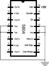
Figure 16-1 The UCN 5804 Stepper Motor Controller Pinout.
Although the 5804 is no longer in production, it is still readily available in the United States. The current limitation of 1.25 A has led to other designs in which the driver is brought outside the chip. The Septronics StepGenie is a popular substitute for the 5804. In the StepGenie, the driver consists of four externals HEXFETs that allow a current rating of 15 A.
Another factor in the demise of the 5804 is the fact that the IC can only drive a unipolar motor. A more flexible circuit design is to use a chip, such as the L297, which is also compatible with bipolar drivers. Because unipolar motors can be driven in bipolar mode (with some possible gain in power), this approach is often preferable.
Typically, the L297 receives command signals from a microcontroller and furnishes all the necessary drive signals to the power element. In driving bipolar motors, it is usually combined with the L298 or the L293E, which are dual, full-bridge drivers. A quad Darlington array or HEXFETs can also be used in the power stage. The input signals into the L297 are step (labeled CLOCK), direction, half-step or full-step, enable, and a reset line. The ENABLE line is active high and can be used to turn on and off the chip’s output. There is also an output line labeled HOME that signals that the IC is in its initial state.
A SYNC line is an output for the chip’s chopper oscillator (choppers are covered in Chapter 19) and can also be used to input an external clock signal, although the L297 has its own oscillator. The motor output lines are labeled A, B, C, and D. Several other pin functions are also present, including two inhibit lines, labeled INH1 and INH2, which are active low controls for the drivers. INH1 inhibits the A and B phases, and INH2 the C and D phases.
The minimal circuit configuration for the L297 is shown in Figure 16-2.

Figure 16-2 Minimal Circuit Wiring for the L297 IC.
In Figure 16-2 the lines labeled RPx are possible connections to a microcontroller port. The lines labeled NC are not connected in this minimal circuit configuration and are left floating. In other circuits, shown later in this chapter, the unconnected lines of Figure 16-2 are wired to pins in the driver stage. Two lines inhibit control of the two driver stages. These are labeled INH1 and INH2 in the diagram. Because these lines are active low, they must be held high in the minimal configuration. Other unused lines are either left floating or brought to ground, as shown in the illustration.
Although the L297 is often employed in simple drivers, it is actually most useful when the circuit takes advantage of all the capabilities of the IC. In one application the L297 can be configured in a “chopper” scheme, consisting of a closed-loop feedback system. This action is based on the fact that bipolar motors require a high current at the start of the step, but at some point in the cycle this current can be reduced to a minimum until the next step begins. The L297 accomplishes the chopping function by comparing the current through the motor coil with a reference voltage on its pin 15 (labeled Vref in Figure 16-2). When the coil current exceeds the reference value it is “chopped off” for the remainder of the power step. A trimmer potentiometer is included in the circuit so as to adjust the reference voltage to provide maximum torque with minimal waste of power. Later in this chapter we develop a complete circuit that uses the L297 in this manner
This is a bipolar controller somewhat different from the L297. The EDE1204 IC is furnished in an 18-pin package that provides both external controls and self-clocking. Figure 16-3 is a functional diagram of the 1204.

Figure 16-3 EDE 1204 Stepper Motor Controller Pinout.
The full-step run mode is activated by setting pin 10 low. In this mode, the direction pin (pin 7) makes the motor rotate clockwise or counterclockwise; the half-step control can be used to double the resolution, and speed control pins A, B, and C (pins 11, 12 and 13) allow selecting eight possible speeds. This appears to result in sixteen possible speeds, eight in full-step mode and eight in half-step mode. In reality, three speeds in full-step mode are duplicated in the half-step mode, so the total number of different speeds is actually thirteen. When the run pin is set high, then the 1204 goes into the step mode, and the motor speed is determined with the clock signal received on the step pin (pin 9). In the step mode the direction and half-step pins continue to be active. The free spin pin (pin 6), which is active low, serves to deactivate both motor coils. This results in a suspension of the breaking effect that is characteristic of stepper motors. Another interesting feature is that the IDE 1204 can change the stepping rate while the motor is running.
The self-clocking feature of the 1204, which results in speed control without an external clock signal, allows for simplification of some simple stepper motor circuits. For example, it is possible to provide speed selection and rotation direction by directly reading input devices, thus eliminating the microcontroller element from the circuit. Circuits in which the microcontroller is overburdened by other tasks can also benefit from this simplification.
The SLA7060M, from Allegro Microsystems, provides both control and drive functions for two-phase, unipolar stepper motors. Their principal feature is that they include the translator and the driver in a single IC. The SLA7060 can use pulse width modulation (PWM) to control the output current, thus supporting microstepping. Microstepping circuits are covered in Chapter 19. The SLA7024M, SLA7026M, and SMA7029M, also from Allegro, are also two-phase, unipolar stepper motor controller/driver ICs, which include NMOS FETs that support high-current and high-voltage output. The differences in the three ICs are current ratings and package styles.
The driver phase of a stepper motor circuit provides power to the motor windings at the necessary current. The specific components used in this stage depend on the motor characteristics as well as the circuit design. The driver phase components are determined by the motor type: unipolar or bipolar.
Unipolar circuits require simple drivers consisting of transistors that serve as current amplifiers, and possibly diodes to prevent damaging backflows. The most common transistors used in unipolar drivers are Darlington transistors. Internally the Darlington consists of two bipolar NPN transistors connected back-to-back so the cur rent output of the first one is further amplified by the second one. This double-stage design is called a Darlington pair. Darlington pairs come in an array packaged in an integrated circuit, such as the ULN2803, or as individual transistors such as the TIP120.
PIC Microcontroller as a Driver
We have mentioned that a PIC microcontroller can conveniently serve as a translator by furnishing the required sequence of power signals for a unipolar stepper motor. But using a PIC microcontroller to drive a stepper motor presents difficulties. The main concern is that the current-carrying capacity of a PIC port pin is 20 mA. This means that only a very, very small motor could be driven directly.
Most real-world circuits require additional amperage for the driver stage. The most common solution is to use several transistors. But here again, the current-carrying capacity of the base pin of some transistors exceeds the 20-mA limitation of the PIC port. For example, the TIP120 Darlington transistor, frequently used in stepper motor circuits, can handle up to 120 mA base current. Although with small loads it is possible to drive a TIP120 transistor directly from a PIC port, a more common design is to use a current gain device. In this application the CMOS 4050 hex non-inverting buffer IC can be placed between the PIC and the TIP120 because the 4050 furnishes sufficient current gain (called fanout) to safely drive the base pin of a TIP120 transistor, even at maximum loads. One of the circuits developed later in this chapter uses a PIC16F84 translator and a 4050 IC to drive four TIP120 transistors.
This is one of five members of the ULN280x family; the 2803 is compatible with 5V TTL/CMOS inputs and therefore can be connected directly to a PIC microcontroller port. The IC packages eight Darlington pairs in a DIP 18 IC that also includes integral suppression diodes. All transistors share a common emitter, thus saving electronic hardware. The current rating of the 2803 is of 500 mA at a maximum of 50V. For driving a unipolar stepper motor only four of the eight diodes are used. Figure 16-4 shows the pinout of the ULN2303.
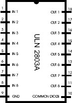
Figure 16-4 ULN 2803 Pinout.
In a typical system, the common diode line of the 2803 (pin 10) is wired to the motor’s power line (which we have labeled Vm). Inputs from the translator stage are wired to the IN x lines and the OUT x lines are connected to the motor windings. The mapping of the IN lines, to the motor windings is determined from the motor’s step sequence.
The TIP120, already mentioned, is an NPN Darlington transistor in a TO-220 package. It is rated at 5 A and 60V. The TIP120 is described as a general-purpose amplifier at low switching speeds. Figure 16-5 shows the TIP120 transistor and its electronic symbol.

Figure 16-5 TIP120 Amplifier Transistor.
The TIP120 contains an internal diode but some circuits include a fast, external one on the emitter pin as additional protection. In a typical circuit, the base pin provides input from the controller, the collector serves as output to the motor winding, and the emitter line is set to ground.
Bipolar motors have a single winding per phase, and rotation is achieved by reversing the current flow in each winding. The most common device for reversing the current flow in a DC circuit is called an H bridge.
In operation, the H bridge can be visualized as four switches placed along the vertical arms of an H-shaped component, as shown in Figure 16-6.

Figure 16-6 H Bridge Circuit Visualization.
In an actual circuit, the four switches, labeled SW A, SW B, SW C, and SW D in Figure 16-6, take the place of four transistors. In H bridge terminology, switches SW A and SW C are said to be on the left side of the bridge, while SW B and SW D are on the right side. Switches SW A and SW B are on the high side and SW C and SW D on the low side of the bridge. When SW A and SW D are closed, the current flows through the motor winding in one direction. When SW A and SW D are open and SW B and SW C are closed, the current flows in the opposite direction. When all four switches are open, there is no flow through the circuit. Also note that if SW A and SW C are open (or SW B and SW D), the input voltage source would be in short circuit and damage to the components is likely. Because a bipolar stepper motors has two motor windings, two H bridges are required to drive it.
H bridges can be built using individual components, usually MOSFET transistors, and are also furnished in dedicated ICs. The L298, discussed later in this section, is one such H bridge IC.
16.4.3 Transistorized H Bridge
When individual transistors are used it is common to select two P-channel MOSFETs for the high side of the bridge, and two N-channel MOSFETs for the low side. Figure 16-7 shows a popular H bridge design using P- and N-channel MOSFETs.

Figure 16-7 NPN-PNP Transistor H Bridge.
The two transistors labeled NPN(I) provide an interface with the IC that supplies the input signals. These transistors can be the 2N2222 or any small-signal equivalent. Many NPN-PNP transistor pairs are suitable for the H bridge itself. The matched pairs with identical characteristics are usually called complementary transistors. The NPN ZTX690B and the PNP ZTX790B in a TO-92 packages, are a matched pairs that deliver up to 2 Amps per coil. The TIP 3055 (NPN) and the TIP2955 (PNP) are also suitable and provide a 15 Amp current gain. Integrated circuits, such as the BC847BPN, are transistor pairs that include the NPN and PNP components. Note that the H bridge in Figure 16-7 supplies a single motor coil. To drive a bipolar motor, two such H-bridges are required. A more efficient, albeit more complicated, circuit uses N-channel MOSFETs for both the high and the low side.
When inductors are energized and de-energized the magnetic field in the coil builds up (in the energizing phase) and collapses (in the de-energizing phase). During the collapsing phase the changes in the magnetic field in the coil cause a current to be induced and flow in the opposite direction. This flow reversal may damage the switching transistors and other logic components in the circuit. The problem can be prevented by the installation of diodes in such a way so that they will not conduct during normal operation. But when the falling magnetic field causes the current flow to reverse, then diodes conduct the current to ground and away from the transistors and other sensitive components. These are usually caller “snubber” or “clamping” diodes.
The snubber diodes are shown in the H bridge in Figure 16-7. In selecting these diodes, their current carrying capacity and switching speed must be considered. We address this problem in greater detail in forthcoming sections related to motor driver circuits. The four snubber diodes in Figure 16-7. can be either the 1N4007 or the 1N5408.
An alternative to the transistorized H bridge described previously is the use of an integrated circuit driver that furnishes the H bridge function, usually in addition to other driver-level controls. The circuit designer often looks at these additional functionalities in order to determine if an IC driver is appropriate, as the H-bridge component by itself is quite compatible with its transistor-based counterpart, as in Figure 16-7.
A consideration sometimes mentioned in favor of the integrated circuit versions of the H bridge, versus the transistorized option, is the possibility of damage due to improper bridge switch activation with the transistorized variation. This possibility is precluded with the IC component because the damaging connections that can possibly damage circuit components are not allowed by the chip’s logic.
Driver ICs are sometimes designed to complement the functionalities of a specific stepper motor controller. This is the case of the L297 (mentioned earlier in this chapter) and the L298 driver IC. The L297/298 pair provides a powerful set of features as shown by some circuits presented later in this chapter.
There are hundreds of stepper motor driver ICs available on the market. A single company (Allegro Microsystems) produces over twenty different bipolar stepper motor drivers. A listing of their various stepper motor control products by specifications and applications is available at:
http://www.allegromicro.com/en/Products/Categories/ICs/motor.asp
The L293D from ST Microelectronics, SGS Thomson, and other vendors, is a two H-bridge, four-channel driver that includes the appropriate snubber diodes. The SN754410 from Texas Instruments is reputedly an improved substitute for the L293. The L293 is furnished in a sixteen pin DIP. It can drive 1.2 A current per channel; it is typically used to drive NEMA teen-size stepper motors. The L293 can be used to run two DC motors bi-directionally (not covered in this book) or to control the two windings of a bipolar stepper motor. Figure 16-8 is a pin diagram of the L293D.

Figure 16-8 L293D Bipolar Motor Driver Pinout.
One advantage of the L293 is its low price (currently under $2.00); another is its simplicity. There are four input lines that are typically wired to the translator phase. In order to turn the motor on and off, two enable lines are either held high by wiring to the positive power supply or are controlled by the translator. The four output lines are wired to the motor coils. Four ground lines are on the center of the IC, which facilitates a PCB large ground that serves as a heat sink. The IC pin 16 is an input for the logic voltage (typically 5V) and pin 8 is an input for the motor power. A circuit using the L293D driven by a 16F84 PIC (circuit SMB-L293D-1) is presented in Chapter 18. A second circuit (SMB-L297-293D-1) in which an L297 is used in minimal configuration to drive an L293D is also described.
The L298 is a popular high-current dual bridge driver often used in bipolar stepper motor circuits. The supply current can go up to 46V and 4 A, which allows the L298, with appropriate heat sinks, to drive NEMA 23 and larger stepper motors. The IC is offered in Multiwatt15 (vertical and horizontal) and PowerSO20 Packages. Figure 16-9 shows the pinout and mechanical data for the L298 driver IC in the vertical configuration.

Figure 16-9 Pinout and Mechanical Data for L298 in Mutiwatt15 Package.
Circuits that use the L298 as a bipolar driver range widely in complexity. In its simplest circuit version, the L298 receives coil inputs through its IN 1 to IN 4 lines and sends output to the motor through the OUT 1 to OUT 4 lines (see Figure 16-9). The controller in these circuits can be a microcontroller or another IC. In these simple configurations the ENABLE A and ENABLE B lines are held high while the SENSE A and SENSE B lines are wired to ground. In all implementations the Vs line is wired to the circuit’s logic voltage supply and the Vm line to the motor power supply. Because the L298 does not include snubber diodes, these must be provided separately. Circuit SMB-298-1, presented later in Chapter 18, shows a simple circuit in which the L298 is used mostly as a high-current capacity double-H bridge. Other more complex L298 circuits are combined with the L297, or other controllers, to provide chop ping, pulse width modulation, and microstepping. These more advanced circuits are discussed in Chapter 19.
16.5 Modules in Circuit Schematics
Previously we classified stepper motor circuit functions into three types: control, translator, and driver. We also noted that many commercial devices include functions from more than one group. In this context we find many circuits in which an IC performs both translator and driver functions, or those in which a microcontroller is programmed to drive a stepper motor, sometimes with no other support than a digital buffer. For practical purposes rather than to divide circuits into control, translator, and driver stages, it is preferable to modularize as follows:
• The control and translator stage include input and output devices and digital logic. In this stage the input data is processed and output is sent to the driver stage or to other circuit devices.
• The driver stage includes the power driver function as well as motor-specific control functions.
Two advantages of this modularization are reusability and the possibility of shuffling stages to suit a particular design. The control and translator stage can be used with several compatible drivers by developing ad-hoc software. For example, a circuit module that contains several toggle and pushbutton switches and a 16F84 microcontroller can be paired with either a unipolar or bipolar driver. In either case, the program running on the microcontroller makes the circuit suitable for the particular motor type.
16.5.1 Example 16F84 Translator Modules
For many stepper motor control applications, the microprocessor provides state code for each of four motor coil lines. When a motor controller IC is present in the circuit, the microprocessor provides a step pulse and one or more motor controls, such as forward or reverse direction, mode selection, or enable and disable controls. A useful circuit can be designed around the 16F84 PIC and several switches, such as the one in Figure 16-10.

Figure 16-10 Pushbutton and Toggle-switch Control and Translator Module.
In circuit IO-PIC16F84-1 (Figure 16-10), input can come from any combination of four pushbutton switches, wired to port A lines RA0 to RA3, or from any of the four toggle switches in the bank wired to port B lines RB4 to RB7. Four output lines are available to communicate with devices or to provide controls for the driver stage. These four lines are wired to port B, lines B0 to RB3. The circuit is intended as a general-purpose experimenter.
The circuit designer can easily modify it to suit a specific purpose by eliminating unneeded components or replacing others. In the circuit in Figure 16-11 we have replaced the pushbutton switches with a second bank of toggle switches.
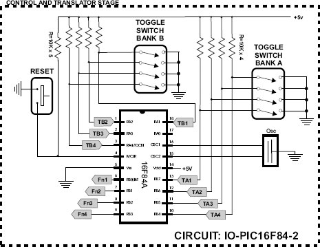
Figure 16-11 Toggle-Switch Based Control and Translator Module.
In most of the circuit schematics for motor controls presented in the following chapters, we have separated the control and translator stage from the driver stage. However, we have abstained from using generic stages that do not exactly fit the circuit at hand. The use of generic stages, such as the ones in Figure 16-10 and Figure 16-11, would have resulted in circuits that contain unused components and therefore are inefficient and confusing. The developer wishing to experiment with motor controls can build the generic control and translator stage circuits in this present section, or the ones contained in other circuit schematics, and use them to control the compatible driver stages. The number and type of outputs from a control and translator stage will clearly define if it is compatible with a particular driver. Circuit designations in the schematics include both the control and translator stage, and the driver stage.