Unipolar Motor Circuits and Programs
17.1 Stepper Motor Control Circuits
The circuits and programs presented in this chapter relate to unipolar motors. Chapter 18 is devoted to basic circuits and programs for driving bipolar motors. The reader should keep in mind that unipolar motors can be used with bipolar circuits by ignoring the center taps, which can be left floating. The same is not true of bipolar motors, which require variations in the current polarity and, therefore, are not compatible with unipolar circuits.
In general, bipolar motors and circuits provide better performance and efficiency than the unipolar ones. On the other hand, unipolar circuits are easier to design, code, and fabricate. For this reason, if the requirements of the application allow, a unipolar circuit may sometimes be preferable, despite its lower efficiency and performance.
17.1.1 Stepper Motor Circuit Schematic Conventions
The naming convention that we have adopted for stepper motor circuits always starts with the letters SM, followed by U for unipolar applications and B for bipolar. The remainder of the circuit designation includes the names of the one or more ICs in the circuit. For example: SMU-5804-1 is a unipolar stepper motor controller that uses the 5804 driver IC. The last digit is the circuit version, notwithstanding that often there is only one version of the circuit. Each circuit is furnished with one or more programs that exercise the circuit’s basic operations. The names of the source files for the programs also follow these conventions. For example, the program named SMU_5804.asm is the source files for driving a unipolar stepper motor circuit based on the 5804 IC. The code listing and the circuit diagrams are cross-referenced.
In order to keep the circuit diagrams as useful as possible we have sometimes structured or simplified the schematics. For example, in most circuits we have separated the schematics into stages that are relatively independent. In these cases the circuit diagrams contain dashed-line boxes that indicate the individual stages. Figure 17-1 shows a circuit that is separated into two stages.
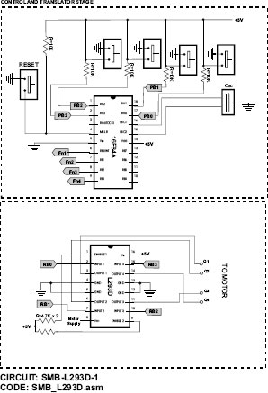
Figure 17-1 Exampleof Circuit Schematic.
The circuit in Figure 17-1 is that of a bipolar stepper motor controller described in Chapter 18. Each stage in a circuit diagram is identified with a variation of the circuit name. In the case of the circuit in Figure 17-1, the translator and control stage is labeled, at the bottom of the illustration, SMB-L297-298-1 and the driver stage is labeled SMB-L297-298-2. The separation of a circuit into stages is complemented by using directed flags that reference the corresponding element in each stage. The flags are labeled FnX, where X is a sequential digit indicating a particular function. For example, in the diagram of Figure 17-1, the flag labeled Fn 1 in the translator and control stage is shown to access the L297 ENABLE function in the driver stage. Also note that not all outputs from the schematics of the translator and control stage are used in the driver stage of a particular circuit.
Stepper motor speed is determined by two factors: the code sequence sent to the motor coils and the pulse rate. These two factors are related: At the same pulse rate a stepper motor in wave drive mode runs twice as fast as one in the half step mode. Later in this book we discuss microstepping techniques that reduce the motor speed even further for the same pulse rate.
In any case, within a specific drive mode (wave, full, half, or microstep), the motor speed is determined by the rate at which the pulses are sent to the motor coils. When a microcontroller is used in the driver stage, as is the case with the circuits and programs in this book, then software will determine the pulse rate. In code the actual pulse rate can be obtained using simple delay counters or by Interrupt-Driven routines. Timer-related issues were discussed in Chapter 11. At present we are concerned with hardware devices that furnish a way of inputting motor speed information into the circuit.
The first issue in implementing a motor speed control mechanism is the device or devices that provides speed selection information to the circuit. In other words, the circuit typically includes input devices that allow selecting the motor speed. These devices are either digital or analog in nature. A toggle switch used to select between a low and a high motor speed can be considered a digital input device because the switch can be wired so that it reports either a high or low state. A potentiometer that allows controlling motor speed within a certain range can be considered an analog input device because the varying resistance read from the potentiometer must be converted to a digital value; this value is then used by the microcontroller to select a motor pulse rate.
17.2.1 Speed Control from Digital Input
The simplest (but not always the most convenient) mechanism for controlling motor speed is an input device that directly provides digital data or can be easily converted to digital form. In the sample circuit SMU-PIC16F84-1 (Figure 17-3), slow and fast motor rates are determined by the state pushbutton switches. The switches are wired so that the pushbuttons reports a high or low value to a microcontroller port. Because the state of the switch can be interpreted as a binary zero or one, the information provided by the pushbutton can be considered digital input. In this same context, sample circuit SMU-5804-1 (Figure 17-4) uses a bank of four toggle switches to provide data that allows selecting sixteen different motor speeds. The program reads the state of the four switches and the binary value is then used to select the corresponding delay in any one of sixteen possible rates.
The use of a bank of switches to select motor speed has its advantages and its drawbacks. With this scheme the number of individual switches in the bank determines the number of possible speeds. One toggle switch allows selecting two speeds, two switches four speeds, three switches eight speeds, and so on. One possible advantage of toggle-switch-based controls is that the motor speed is selected on the board and cannot be changed accidentally. It is a suitable option for circuits in which the motor speed is not changed often and can be scaled in discrete steps. By the same token, the toggle switch bank approach is not suitable when the motor speed must be easily changed or must have a continuous range. Another drawback of switch controls is that each switch requires using a microcontroller port. Sample circuits SMU-PIC16F84-1 and SMU-5804-1 use digital inputs to control motor speed. In one case (SMU-PIC16F84-1), pushbutton switches select slow or fast motor speeds, in the other case (SMU-5804-1), a battery of four toggle switches (see Figure 14-4) is used to select one of sixteen possible motor speeds.
17.2.2 Analog Input Speed Control
An analog input device provides an alternative way of controlling motor speed. The potentiometer (also called a pot) performs as avariable resistor and acts as a voltage divider. Another analog device for varying circuit resistance is the rheostat. The rheostat is a two-terminal variable resistor that allows handling much larger currents than a potentiometer.
Potentiometers are often used to adjust an analog signal that is then fed into a higher-wattage device (such as a TRIAC) or converted to a digital scale. This second option is the one most often found in microcontroller-driven stepper motor circuits, which also explains why rheostats are not commonly found in these circuits. The typical circuit reads the resistance offered by the current setting of the potentiometer, converts it to a digital value, and uses this value to determine the pulse rate sent to the motor coils. The one new element in a pot-based circuit is the conversion of the analog value read from the potentiometer into a scale of digital values that can be used by the microcontroller.
In this application the circuit designer can select one of two options: use an analog-to-digital conversion device, such as the ADC0831, or select a microcontroller that contains an analog-to-digital converter. These internal analog-to-digital devices are referred to in the literature as an A/D or ADC module. Selecting a microcontroller with an ADC module is often more economical and easier to implement than using a separate analog-to-digital IC.
Many PIC microcontrollers contain an ADC module. The most suitable one in each case depends on the circuit requirements. Unfortunately, the popular 16F84, used in many circuits in this book, does not contain an ADC module. On the other hand, the 16F87x family, which includes the forty-pin 16F877 used in many of this book’s circuits, contains an ADC module. An interesting option for compact stepper motor circuits is the PIC16F684, which also includes an ADC component. The 16F686 is a small, inexpensive device with the same instruction set as the 16F84 and very similar architecture and memory structure. The chip provides twelve I/O ports: six mapped to port A and six to Port C. An internal oscillator is programmable from 31 KHz to 8 MHz, the default being 4 MHz. This saves having to use an external timing device. The 16F684 has two timer modules and a comparator. The ADC converter has a resolution of ten binary digits. The circuit diagram of the 16F684 is shown in Figure 17-2.
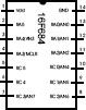
Figure 17-2 Diagram of the Fourteen-Pin Versions of the PIC 16F684.
Later in this chapter we develop the circuit named SMU-PIC16F684-1, which contains a 16F684 PIC. Two sample programs (SMU_PIC16F684.asm and SMU_PIC16F684_INT.asm) use the PIC’s ADC to convert the resistance value read from the potentiometer to digital, which is then used to control motor speed.
17.3 Unipolar Motor Control Circuits
Unipolar motor control circuits require fewer components and are easier to design and manufacture than their bipolar counterparts. In the simplest possible implementation, a microcontroller (such as a PIC 16F84 or 16F684) can be used as a controller, usually combined with some simple devices that augment the current capacity to match the needs of the motor. Other more complex circuits use dedicated translators and drivers to relieve the microcontroller of some functions or to provide additional functionalities.
17.3.1 Matching Circuit to Motor Power
Stepper motors come in many sizes and power ranges. Sometimes the motor’s datasheet expresses the motor’s power requirements as its maximum current rating per coil. When this value is known, it can be directly compared to the ratings of the circuit components. For example, a motor rated at 0.8 A can be safely used with a 5804 motor driver IC that is rated at 1.25 A.
If the datasheet is not available or if the motor’s current rating is not listed, then we can determine the motor’s power requirements by measuring the coil resistance with an ohmmeter or a multimeter. In the case of a unipolar motor, make sure that the measured value is between the ends of the coil and not from the coil center taps. If in doubt use the larger resistance value.
For example, suppose you have a 14V stepper motor and that the measured resistance of the windings is 5 Ohm. Ohm’s law allows us to calculate:
In the case of a 5804 driver, this value considerably exceeds the 1.25 A at which it is rated. Two possible solutions are available when the motor current exceeds the capacity of the circuit component: the first one is to select components with a higher power rating. The second possible solution is to add resistance to the motor coils. In this case Ohm’s law can be used to determine the total coil resistance necessary to meet the limits of the hardware. In the previous example we can calculate
Because the measured coil resistance is 5 Ohm we would need external resistors of 6 or 7 Ohms so that the total coil resistance would be approximately 11.2 Ohms. Also note that the wattage of the resistor must also be calculated. In this case the external resistors should be rated for 17 W. Resistors of 20 W are commonly available.
In the unipolar circuits that follow, we have included a resistor labeled Rx connected to the center tap of the motor coils. This resistor will only be necessary if the motor rating exceeds the circuit capacity as determined at its output.
The first circuit is a simple unipolar motor driver that uses the 16F84 PIC as a translator with a 4050 hex buffer IC and four TIP 120 NPN Darlington transistors as amplifiers. Although the TIP 120 contains internal snubber diodes, externals ones are provided in the circuit as additional protection. Figure 17-3 shows the circuit schematics.
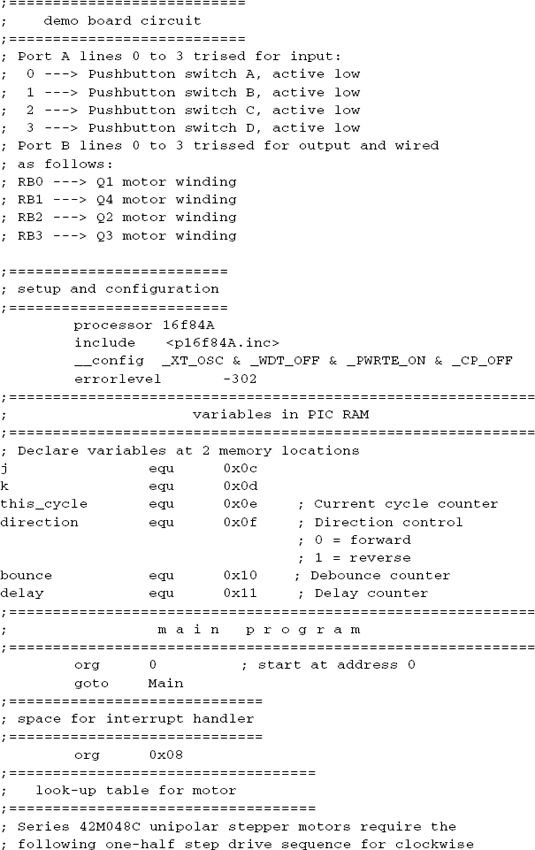
The circuit SMU-PIC16F84-1/2 in Figure 17-3 receives input from four pushbutton switches wired to the microcontroller port A lines 0 to 3. Port B lines 0 to 3 furnish outputs to the four coils of the unipolar motor via the 4050 hex buffer and the base pins of the TIP 120 transistors. Output from the four TIP 120 transistors are wired to the respective ends of the motor coils. The center taps of the coils are connected to the motor power source. The resistors labeled Rx are only necessary if the motor exceeds the capacity of the TIP 120 transistors, which is 6 A. The calculation of the Rx resistors was discussed earlier in Section 17.3.1.
Sample Program SMU_PIC16F84.asm
The program SMU_PIC16F84.asm, in this book’s software package, is a driver that exercises the circuit. The code assumes a unipolar motor in one-half step mode and uses a lookup table for the corresponding coil sequence codes. When held down, the pushbuttons wired to ports A3 and A2 activate slow rotation in the forward and reverse direction. Pushbuttons wired to ports A0 and A1 activate fast forward and reverse rotation. The pointer to the lookup table is either incremented or decremented according to the selected direction. This ensures that changes in the direction of rotation are executed smoothly. Fast and slow execution are determined by the value of a local variable read by the delay routine.
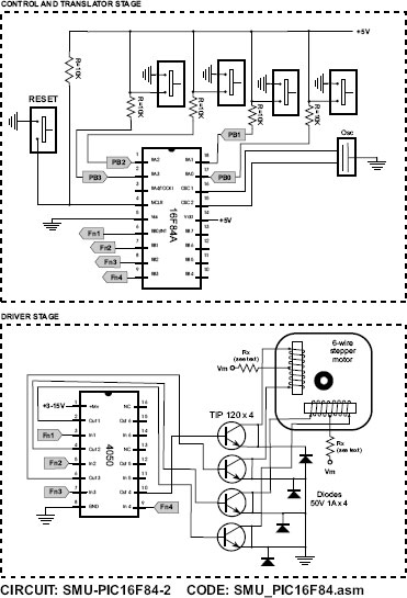
Figure 17-3 Unipolar Motor Driver with the 16F84 PIC.
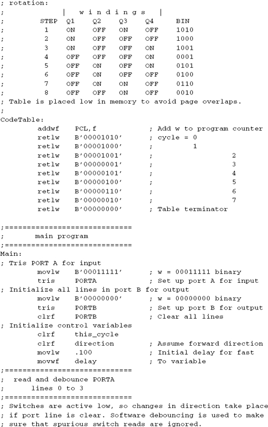
The code table matches the requirement of the 42M048A19 unipolar motor manufactured by Airpak. The motor is rated for 5VDC at 9.1 Ohms per coil. The degrees per step is 7.5. The table is coded as follows:

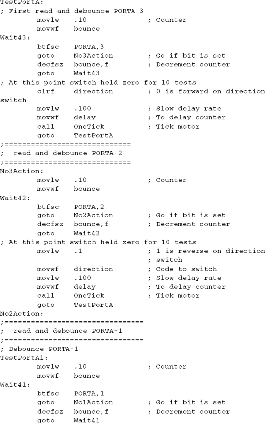
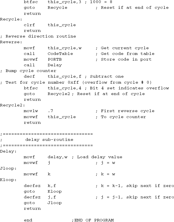
Processing consists of reading the state of the four pushbutton switches wired to port A lines and setting the values of the variables that control direction and motor speed. The switches are debounced in software to avoid spurious values. The driver then goes to a routine that obtains the corresponding table code and writes it to port B lines 0 to 3. The procedure named OneTick obtains the corresponding code from the table in forward or reverse rotation and writes the code to port B. In forward direction, the table pointer is incremented and it is decremented in reverse rotation. The procedure then calls a Delay procedure that waits doing nothing. The duration of the wait, thus the speed of the motor, is determined by the value stored in a local variable. Code is as follows:

The complete listing for the SMU_PIC16F84 program is found in this book’s software resource.
Easy interfacing with small-size stepper motors can be achieved with circuits that employ the 5804 IC. As mentioned in Chapter 16, the 5804 allows enabling output, and controlling direction and half-step or full-step modes. A step input line, which is typically driven by a clock IC or a microcontroller, can be programmed to set the motor speed. Several speed control mechanisms are examined in the following sections. The 5804 provides thermal protection so as to disable the chip when the safe operating temperature is exceeded. Internal fly-back diodes are also part of the IC, although external diodes are sometimes included as a safeguard.
One limitation often mentioned in relation to circuits based on the 5804 is the IC’s limitation of 1.25A per phase. However, most teen-size stepper motors of 5V and greater fall within this range. For example, the Airpax 9123 stepper motor, which is size NEMA 16, is rated at 5 V and 9.1 Ohms per coil. This results in a current value of 0.55 A, well below the 1.2 A rating of the circuit. Even some larger-than-teen stepper motors are compatible with the 5804 circuit. For example, a NEMA size 22 unipolar stepper motor (2.2 inches wide) rated at 12V, draws only 0.6 A per coil.
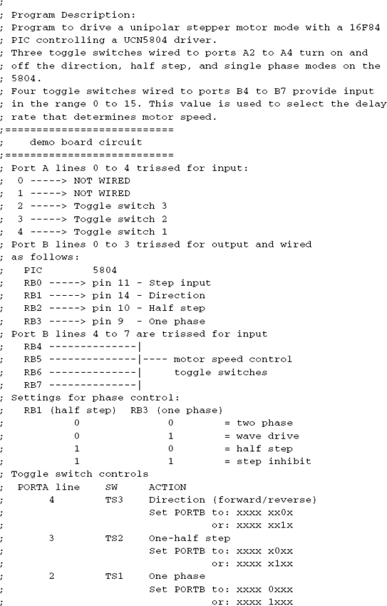
The circuit in Figure 17-4 can receive input from two sets of toggle switches. One set of three switches is wired to 16F84 port A lines 2 to 4. These three switches are used to determine the 5804 motor controls. Another set of four toggle switches is wired to the 16F84 port B lines 4 to 7 and is used to determine the motor speed. Two port A lines (RA0 and RA1) are unused in the circuit. The developer can use these lines for additional controls.

Figure 17-4 5804-Based Unipolar Motor Driver Circuit.
In circuit SMU-5804-1/2 (Figure 17-4), there are four control lines from the 16F84 to the 5804. The line labeled Step In provides the strobe pulse to the 5804. The line labeled Dir furnishes direction control, while the lines labeled Half Step and One Phase allow selecting four drive sequences, as follows:

Note that the diodes in the circuit can be omitted and that the resistors labeled Rx are necessary only if the motor exceeds the 1.2 A.
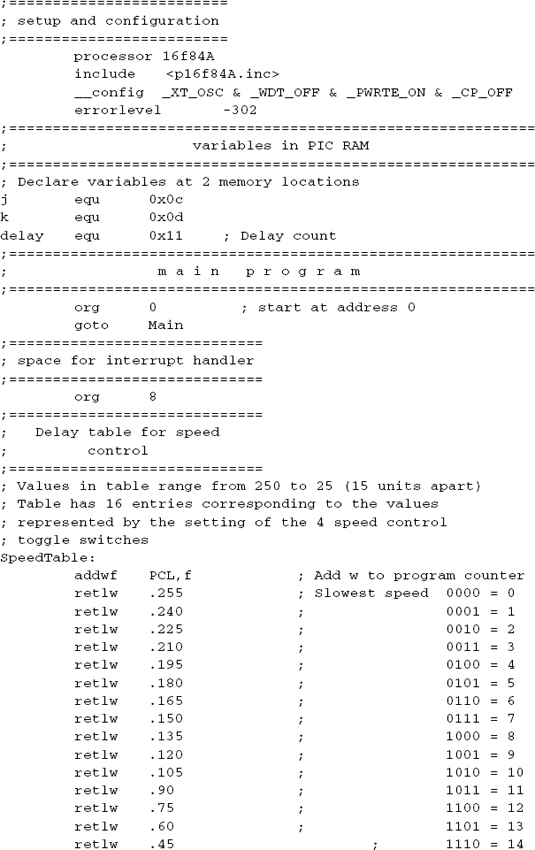
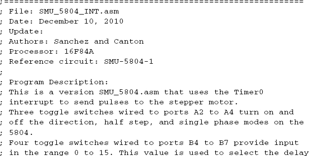
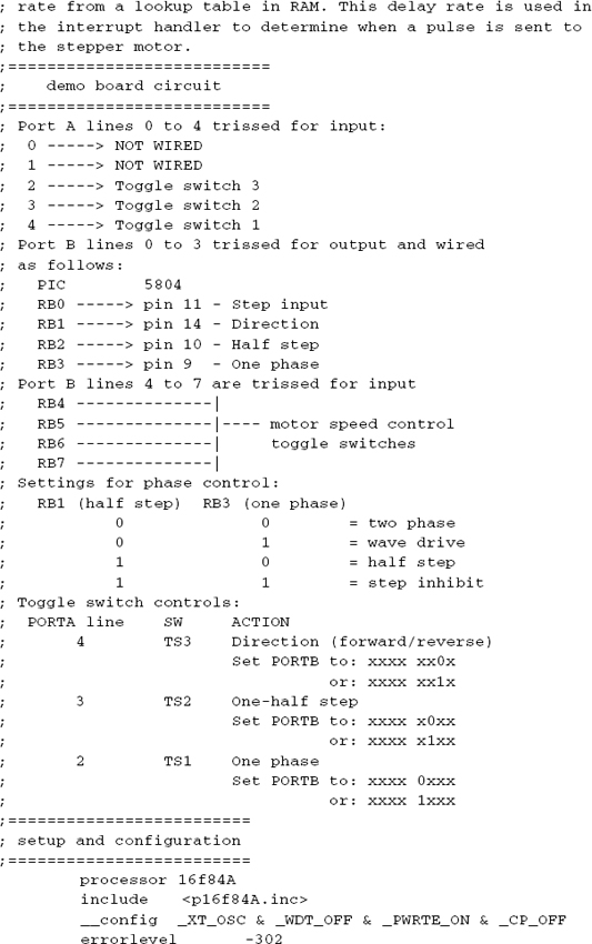
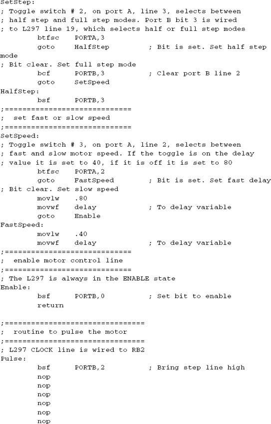
The program SMU_5804.asm, in this book’s software package, is a driver that exercises the SMU-5804-1 circuit (Figure 17-4). The code reads the three toggle switches wired to port A lines 2, 3, and 4 and selects the speed, direction, and drive mode, as follows:

The circuit contains pushbuttons wired to ports A0 and A1, which are not used by the sample program.
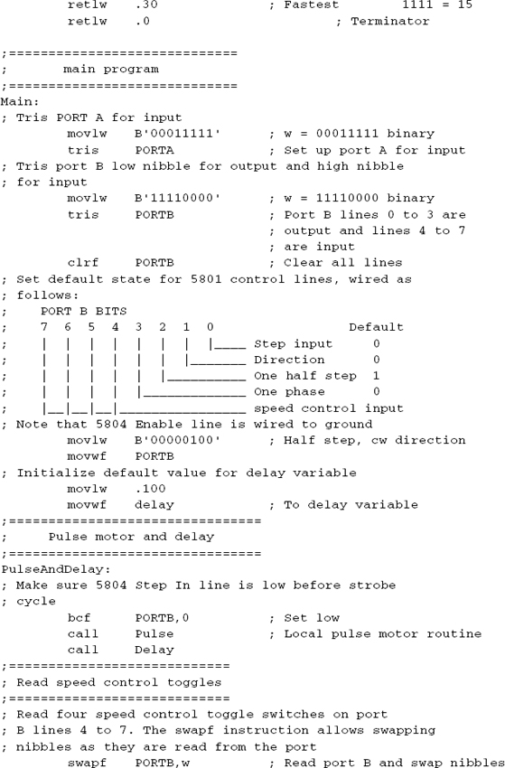
The program first reads port B lines 4 to 7, trissed for input and wired to the four toggle switch bank. The value in the range 0 to 15 read from the four toggle switches is used to obtain a delay code from a local lookup table to determine slow or fast speed. Code is as follows:

The developer can edit the table to suit the particular requirements of a motor or circuit.
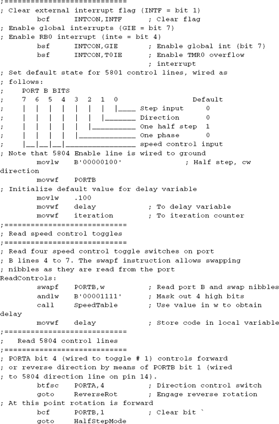
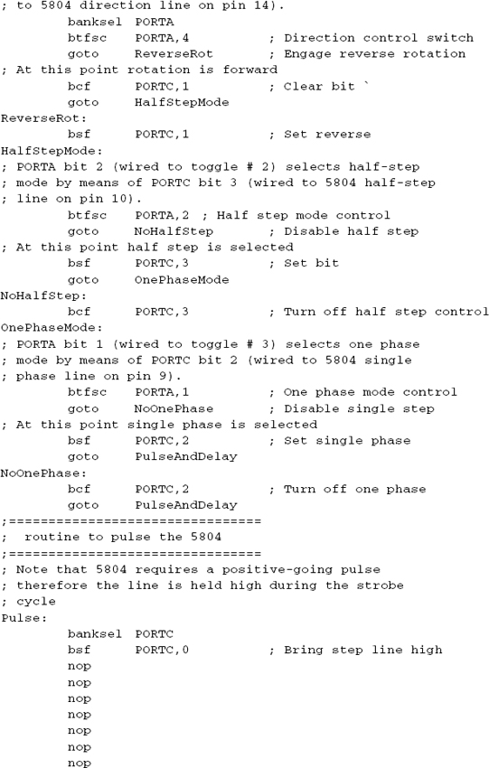
After the delay rate has been set, code reads the three port A lines wired that will determine the settings of the 5804 direction, one-half step, and one phase controls. Code is as follows:

Note that the code for reading pushbutton switches (in the sample program SMU_16F84.asm) includes debouncing. However, we have found that debouncing switch action can usually be omitted when reading toggle switches in motor-driving circuits. For this reason switch debouncing operations are not used in the program SMU_5804.asm.
Note the difference between the sample program SMU_16F84 and SMU_5804 regarding the generation of the motor-driving pulses. The first program (SMU_16F84) reads the drive sequence codes from a local table and writes these codes to the port B lines that are wired to the motor coils. In this case the speed of the motor is determined by the rate at which these coil codes are updated, which, in turn, depends on the delay routine. On the other hand, the sample program SMU_5804 relies on the 5804 IC to produce the corresponding codes. The actual sequence generated by the 5804 depends on whether the half-step or single-step mode has been previously selected. This means that on the 5804 circuit and program, the motor coils are driven by the 5804 IC and not by the microcontroller. The developer should not assume that the code sequence generated by the controller IC is always the same one expected by the motor. The motor’s datasheet usually lists the coil driving sequence for each supported mode. This sequence should match the one generated by the controller chip. If this is not the case, then the motor coil taps must be relabeled so that they are in accordance with the sequence generated by the 5804.
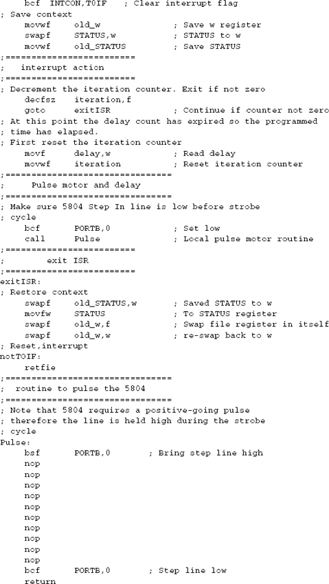
When the motor is driven by a dedicated controller, such as the 5804, a microcontroller is typically required to produce the pulses or strobes that are impressed on the controller’s step line. In circuits without a microcontroller (not covered in this book), a clock or timer IC can be used to generate the strobe pulses. In the circuit SMU-5804-1, the microcontroller’s port B line 1 is wired to the 5804 line labeled Step In.
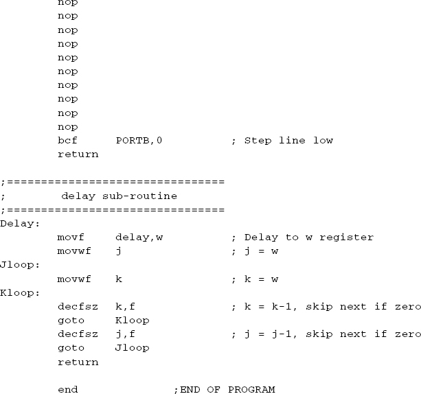
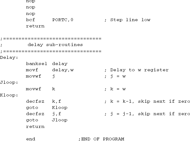
The pulses sent to a specific controller can be positive-going or negative-going. In the positive-going pulse, the line is held low and then strobed high. In a negative-going pulse, the line is held high and strobed low. In either case there is a minimum time during which the line state (high or low) must be maintained. Ideally the device datasheet will provide sufficient information regarding its pulse requirements, but this is not always the case. For instance, the 5804 datasheet does not explicitly state that the pulse must be positive-going, although it is indirectly suggested by the statement in the datasheet that that states that the step input line must be low when changing state or direction. In addition, there is no specific information in the 5804 datasheet regarding the duration of the high strobe. The sample program SMU_5804 contains a sub-routine to pulse the 5804 Step In line. We have coded ten no-operation codes (nop) to produce a delay of as many machine cycles. Code is as follows:

Clearly the delay could have been accomplished more compactly with a timed or counter-based loop. Note that although this routine works well with the 5804, it is not adequate for a device that requires a negative-going pulse or different timing. Later in this chapter we will find that the L298 driver requires a negative-going pulse that must be held low for one machine cycle. A different pulse routine is developed for L298 circuits.
Interrupt-Driven Motor Pulsing
The timing of motor pulses using a delay routine is simple to code and in some cases serves its purpose. However, there are more accurate and efficient ways of generating a timed pulse even with the simplest microcontrollers. Timing circuits and code were covered in Chapter 11 so we discuss only the implementation of interrupt-based timers in the context of motor controls. The methods described in this section can be implemented in any PIC microcontroller covered in the book, although sometimes minor modifications to the code will be required to accommodate the various hardware.
Interrupt-Driven timers have several advantages over polled routines: One is that the timing operation is independent of application code. Because the timing takes place as a background operation, changes in the application itself do not affect the accuracy of the timer. Another advantage is that the application can continue to do other work in the foreground without concern for the accuracy of the timing routine.
The Timer0 module, which is available in all mid-range PICs, is particularly suited for implementing an Interrupt-Driven motor pulsing routine. In this application Timer0 has the following useful features:
• The timer register is readable and writeable by software
• Can be driven by an internal or external clock
• Edge of timing pulse can be selected on the high-to-low or low-to-high transition
• 8-bit prescaler is available
• Can be Interrupt driven
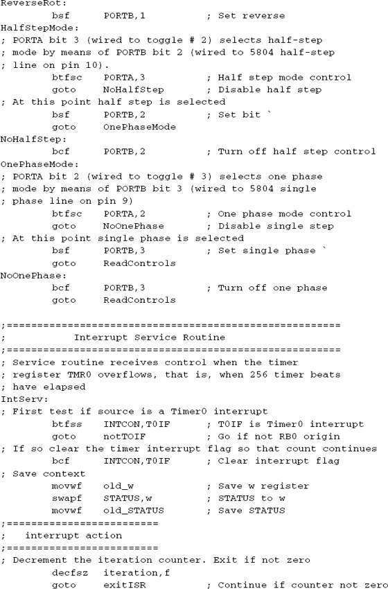
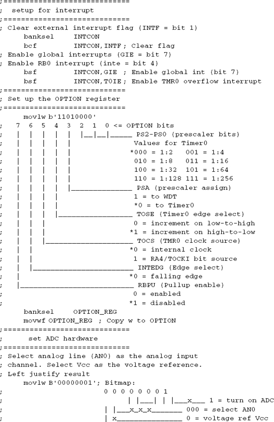
In a simplest implementation, the program sets up the Timer0 interrupt to take place on register overflow, selects a suitable prescaler, and chooses the internal clock source. The sample program SMU_5804_INT.asm, in this book’s software package, proceeds as follows:

Once the Timer0 interrupt is set up and initialized, the interrupt service routine receives control every time the timer register overflows. The service routine uses similar processing for pulsing the motor as the in-line delay routines covered previously. One change is that two counters are now required: one that is set from the input provided by switches or a potentiometer, and a second, running counter that is decremented during each iteration of the service routine. In the sample program SMU_5804_INT.asm, the ISR is coded as follows:

In the Interrupt-Driven sample program named SMU_5804_INT.asm, motor speed is determined by the delay value read from the lookup table and by the value selected for the prescaler. Note that the prescaled delay can be eliminated by assigning the prescaler to the Watchdog timer. When the prescaler is assigned to Timer0, the lowest reduction is in the rate 1:2. However, when the prescaler is assigned to the Watchdog timer no delay of the Timer0 interrupt takes place. In the case of the sample program, we could eliminate the prescaled delay by setting bit 3 of the OPTION register. This would in fact generate the interrupt at double the speed.
By reading the state of each switch in a bank of four toggle switche,s we can obtain sixteen discrete values that can be used to set the motor speed in as many steps (circuit SMU-5804-1, Figure 17-4). However, it is sometimes necessary to devise a circuit that allows controlling motor speed with more precision or more conveniently than is provided by the discrete steps of one or more digital input devices, for example, when the circuit has to provide a finer degree of motor speed control or a more user-friendly device than toggle switches.
Speed control potentiometers are often suitable for this purpose. If the motor speed control is to be available during normal use, then a conventional knob-operated potentiometer can be selected. If the motor speed is to be set during installation or initialization, then a trimmer pot on the board may be more suitable. In either case, the analog resistance reading provided by the potentiometer or trimmer must be converted to digital so that it can be manipulated by code. The PIC 16F684 IC contains an ADC module that can be used for this purpose. Figure 17-5 is a circuit with potentiometer speed control and a 16F684 PIC.
One advantage of potentiometer or trimmer control over toggle switches is that the pot or trimmer requires a single input line. On the other hand, a circuit that contains a potentiometer must include a microcontroller with ADC or a separate analog-to-digital conversion IC.
Transitioning from the 16F84 PIC to the 16F684 is straightforward but not without some complications. Although both PICs belong to the same mid-range family and use the same instruction set, there are architectural differences. In the first place, the 16F684 is a fourteen-pin device in PDIP, SOIC, and TSSOP configurations, while the 16F84 has eighteen pins. This means that the latter PIC cannot be replaced with the former one without making circuit changes. The following are the most notable differences between these PICs:
• The 16F684 has twelve I/O ports, six assigned to port C and six to port A. The 16F84 has thirteen ports: five assigned to port A and eight to port B. There is no port B in the 16F684.

Figure 17-5 Unipolar Motor Driver Circuit with 16F684 PIC.
• The general-purpose registers (GPR) are mapped to addresses 0x0c to 0x4f in the 16F84 (68 registers). In the 16F684 there are ninety-six GPRs mapped to addresses 0x20 to 0x7f and thirty-two additional registers mapped to 0xa0 to 0xbf in bank 1.
• The 16F84 requires an external clock source or oscillator while the 16F684 has an internal precision oscillator. The frequency of the internal oscillator in the 16F684 can be selected by software between 8 MHz and 125 KHz. There is also a 31-KHz internal oscillator.
• The 16F84 requires that the master clear line (mapped to pin 5 and labeled MCLR) be held high for IC operation. In the 16F684 the master clear pin (mapped to pin 4) is multiplexed with port A line 3. During initialization of the 684, software can select between the master clear and the general-purpose I/O function for this line.
• The 16F684 includes several peripherals that are not available in the 16F84. These include an Analog Comparator, and A/D Converter, and an Enhanced Capture, Compare, and PWM module. Other devices, such as the timer, have additional features and functionalities in the 16F684.
In addition to the features compared in the preceding list, the 16F684 datasheet claims many other refinements and advantages over the 16F84. In the context of stepper motor software the A/D converter and the PWM module in the 16F684 are particuiarly useful. Porting code from the 16F84 to the 16F684 consists mostly of taking into account the differences between the two ICs. In addition, code that uses particular features of the 16F684 must initialize and operate these functions.
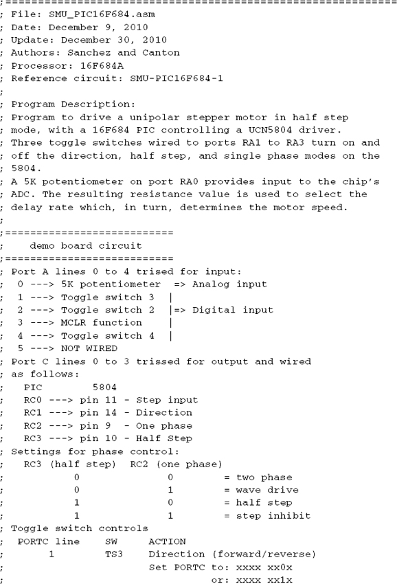
Sample Program SMU_PIC16F684.asm
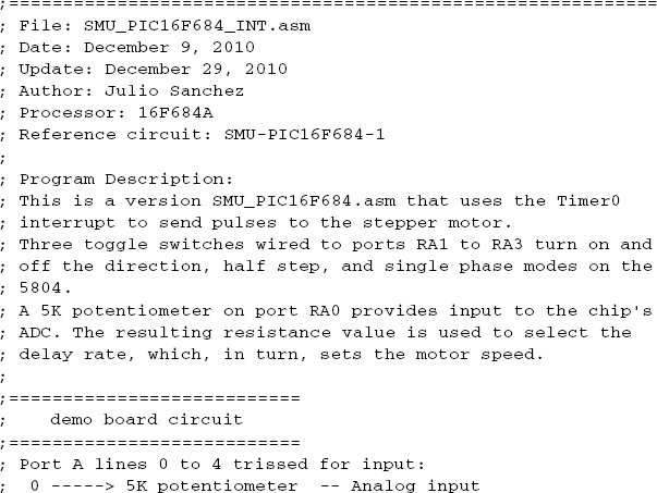
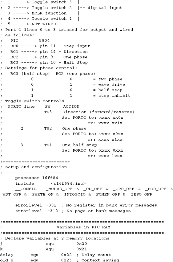
This sample program is designed for the SMU-PIC16F684-1 circuit. The program drives a unipolar stepper motor in half-step mode. The 16F684 PIC controls a UCN5804 driver, which furnishes the motor control. Three toggle switches on the circuit are wired to ports RA1 to RA3. These are used to turn on and off the direction, half-step and single-phase modes on the 5804. A 5K potentiometer on port RA0 provides input to the chip’s ADC. The resulting resistance value is used to select the delay rate, which, in turn, sets the motor speed in a delay routine.
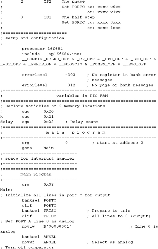
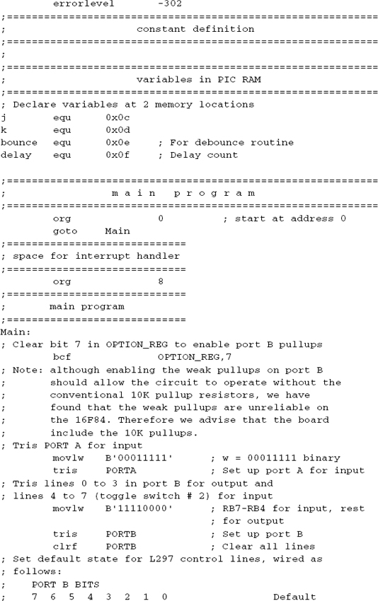
Program variables are defined starting at address 0x20, as follows:

In the sample program we use the banksel directive to select between the two memory banks. Alternatively we could have used bank selection macros or manipulated the RP0 bit directly in code, as discussed earlier in the book.
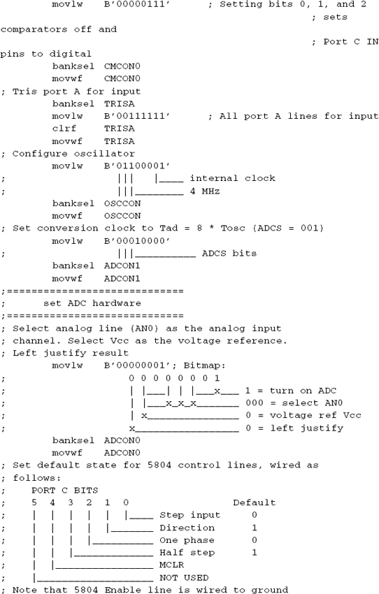
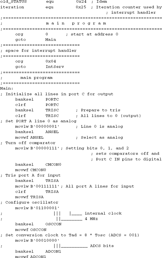
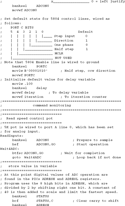
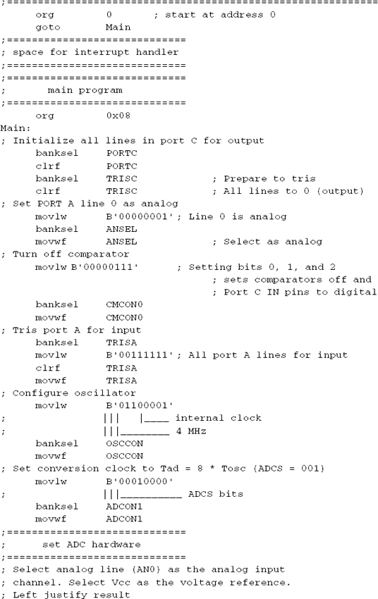
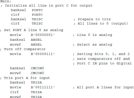
Initialization starts by “trissing” the ports as required by the hardware devices. In this case, port C is set to output and port A to input. Port A line 0 is selected for analog input because this line is connected to the potentiometer in the circuit. Code is as follows:
The second initialization step consists of configuring the oscillator. In this case we have set the oscillator to 4 MHz and set the conversion clock use by the analog-to-digital converter to the value recommended in the 16F684 datasheet. Code is as follows:

Finally, the A/D converter module is initialized and turned on, as follows:

The A/D converter module in the 16F684 provides a 10-bit result that is stored in two dedicated registers labeled ADRESH and ADRESL. The high-order bit of the ADCON0 register, labeled the ADFM bit, is used to select between left- or right-justification of the 10-bit result. In either case, there are six bits that are not significant and are set to zero by the conversion module. The structures of the result registers are shown in Figure 17-6.
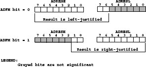
Figure 17-6 Conversion Options in the 16F684 A/D Module.
Once the analog-tdo-igital module has been initialized and an analog line is detfined and wired to the potentiometer, we can perform the read-and-convert operation. The first step consists of setting bit 1 of the ADCON0 register (labeled the GO bit) to start the conversion. Code then tests the state of this bit to determine when the conversion has completed. This is signaled by the A/D module clearing the GO bit. Processing is as follows:

Using a potentiometer to regulate motor speed is usually based on using the resistance value read from the pot to determine the delay between motor pulses. Thus, the higher the resistance, the larger the delay and the slower the motor speed. By the same token, the lower the resistance read from the pot, the faster the motor turns. In most cases the resistance value needs to be scaled so that the resulting delay between pulses matches the minimum and maximum motor speeds desired.
In the case of the 16F684 analog-to-digital module, the 10-bit result stored in the ADRESH and ADRESL registers has a numeric range from 0 to 1023. In most cases we would not need this many motor steps. Program code can manipulate the conversion results to adjust for the desired motor speed range. For example, by selecting left-justification and reading only the ADRESH register, the two low-order bits are eliminated. This will produce a result in the range 0 to 255 instead of 0 to 1023. Often the conversion needs to be scaled further before it can be used as a delay value. This requires performing binary arithmetic on the results of the analog-to-digital conversion. Shifting bits provides an easy way to multiply or divide by two. Adding or subtracting a constant serves to transpose the scale to a higher or lower range.
The sample program SMU_PIC16F684.asm reads the high-order nibble of a left-justified result and halves this value by shifting the bits to the right one position. Then a value of 40 is added to limit the fastest motor speed. Code is as follows:
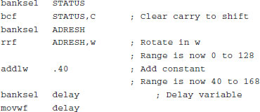
This code ensures that the value stored in the variable named delay is in the range 40 to 168. This range and scale worked well for the particular motor used in testing this circuit; however, this code will need to be modified to suit the characteristics of a different motor or the speed range requirements of the application.
Sample Program SMU_PIC16F684_INT.asm
The interrupt system of the 16F684 is downward compatible with that of the 16F84. For this reason, the Interrupt-Driven motor controls developed in the sample program SMU_5804_INT (which uses the 16F84) can be easily ported to an application that uses the 16F684.
The program SMU_PIC16F684_INT.asm, in this book’s software package, is an Interrupt-Driven version of the program SMU_PIC16F684.asm described in the previous section. The only modification required in the interrupt service routine is replacing the designation for the port wired to the 16F84 step line by the one used by the 16F684.
17.3.6 Stepper Motor Position Control
All the programs and examples considered to this point assume that the stepper motor rotates continuously in one direction or the other, that is, that it performs the conventional function of a classical motor. The control functions discussed so far include speed, direction, and step sequence mode. The motor speed is controlled by the frequency with which the step commands are sent to the hardware. However, because each step code sent to a stepper motor turns the rotor by a fixed angle, it is possible to control the rotor position by counting the number of steps sent to the drive. For example, if a given motor in full step mode turns by 2 degrees for each pulse received, then the software can make the rotor turn by 20 degrees by sending ten consecutive pulses in the selected direction.
Although servo motors (not covered in this book) are designed to provide position control and do so effectively, stepper motors also have this capability. The use of conventional stepper motors in position control functions is convenient in situations in which the device needs to be located at a certain position by the operator. This can be accomplished by “jogging” the motor, typically by operating one or more pushbuttons. Another example of position control is to provide a “slewing” rate or mode so as to re-position a device, for example, to correct the location of a stepper motor-controlled device by adding steps in a given direction.
Sample Program SMU_POSITION.asm
Position control operations are mostly accomplished in software. The circuit typically includes an input source (analog or digital) that provides information regarding the direction, amount, or speed of the movement required. The sample program SMU_PIC16F84.asm, described earlier in this chapter, can be considered a position control application. In this case, the circuit SMU-PIC16F84-1 contains four pushbuttons and the program reads the pushbuttons to jog the motor in the forward or reverse direction at a slow or fast slew rate.
The sample program SMU_POSITION.asm, in this book’s software package, uses the circuit SMU-PIC16F84-1 (Figure 17-5) to illustrate position control. In this case the 5K potentiometer in the circuit is read by the PIC’s ADC module. The resulting resistance value is used to turn the motor a specific number of steps in either direction. Program logic is as follows:
1. During initialization, the current position of the potentiometer arm is stored as the local reference point (LRP).
2. The potentiometer is read by code and designated as new reference point (NRP).
3. NRP and LRP are compared. If they are the same, no action takes place. Execution continues at Step 2.
4. If the NRP is greater than the LRP, then the difference is the number of steps the motor is turned in the clockwise direction.
5. If the NRP is smaller than LRP then the difference is the number of steps the motor is turned in the counterclockwise direction.
6. LRP is now set to NRP.
7. Processing continues at Step 2.
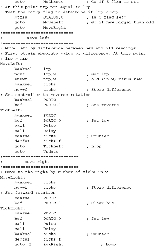
In the program SMU_POSITION.asm, the values of NRP and LRP are stored in local variables called nrp and lrp, respectively. The 16F684 PIC is initialized so that PORTC is output and PORTA is input. PORTA line 0 is designated as analog input and wired to the potentiometer. The ADC hardware is set to left-justify the result because the program only used the eight high-order bits of the resistance reading. Once the local variables are initialized, code proceeds as follows:
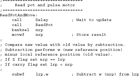
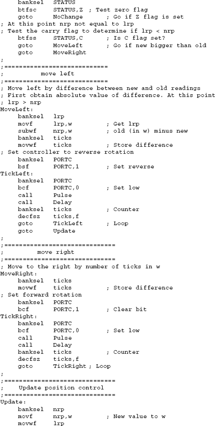
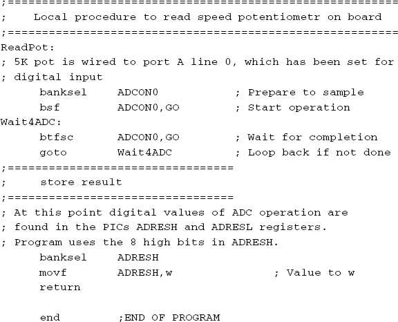
![]()
The local procedures ReadPot, Delay, and Pulse are not listed and can be found in the sample code.
The programs listed in the following section demonstrate the programming discussed in this chapter.


17.4.2 SMU_PIC16F84.asm Program