
8.1 Assembly versus High-Level Languages
Some PIC microcontrollers can be programmed in high-level languages or in their native machine language. Machine language programming is facilitated by the use of an assembler program, and thus becomes assembly language programming. Although assembly language is the most used and popular way of PIC programming, some PIC microcontrollers can also be programmed in high-level languages such as C or BASIC.
The major argument in favor of high-level languages is their ease of use and their faster learning curve. The advantages of assembly language, on the other hand, are better control and greater efficiency. Another consideration is that only higher-level PICs can be programmed in high-level languages. The mid-range PICs, including the 16F877, 16F84, and 16F684 covered in this book can only be programmed in assembly language, which settles the programming language issue in this context.
At the heart of an embedded system is a microcontroller (such as a PIC), sometimes several of them. These devices are programmed to perform one or, at most, a few tasks. In the most typical case an embedded system also includes one or more “peripheral” circuits that are operated by dedicated ICs or use some functionality contained in the microcontroller itself. The term “embedded system” refers to the fact that the device is often found inside another one; for instance, the control circuit is embedded in a microwave oven. Furthermore, embedded systems do not have (in most cases) general-purpose devices such as hard disk drives, video controllers, printers, and network cards.
A typical embedded system is a control for a microwave oven. In this case the controller includes a timer, so that various operations can be clocked; a temperature sensor that provides information regarding the heat inside the oven; perhaps a motor to optionally rotate a table or tray; a sensor to detect when the oven door is open; and a set of pushbutton switches to select the various operational options. A program running on the embedded microcontroller reads the commands and parameters that are input through the keyboard, programs the timer and the rotating table, detects the state of the door, and turns the heating element on and off as required by the user’s selection. Many other daily devices including automobiles, digital cameras, cell phones, and home appliances use embedded systems and many of them are PIC based.
The development process of an embedded system consists of the following steps:
• Define the system specifications. This step includes listing the functions that the system is to perform and determining the tests that will be used to validate their operations.
• Select the system components according to the specifications. This step includes locating the microcontroller that best suits the system as well as the other hardware components.
• Design the system hardware. This includes drawing the circuit diagrams.
• Implement a prototype of the system hardware by means of breadboards, wire wrapping, or another prototyping technology.
• Develop, load, and test the software. Loading software into a PIC is referred to as “blowing” the PIC.
• Implement the final system and test hardware and software.
8.2 Integrated Development Environment
The PIC assembly language development system provided provided by Microchip is named MPLAB. The package is furnished as an integrated development environment (IDE) and can be downloaded from the company’s website at www.microchip.com. One limitation of the MPLAB package is that it is presently furnished only for the PC. If you are a Mac, Unix, or Linux user, you will not be able to use MPLAB. However, other development systems for Mac and Linux are available on the Web. The MPLAB IDE is intended for software development of embedded systems. The software in an embedded system is usually fixed and cannot be easily changed. For this reason it is called “firmware.” The MPLAB development system, or integrated development environment, consists of a system of programs that runs on a PC. This software package is designed to help develop, edit, test, and debug PIC code.
Installing the MPLAB package is straightforward and simple. The package includes the following components:
• MPLAB editor. This tool allows creating and editing the assembly language source code. It behaves very much like any Windows editor and contains the standard editor functions including cut and paste, search and replace, and undo and redo functions.
• MPLAB assembler. The assembler reads the source file produced in the editor and generates either absolute or relocatable code. Absolute code executes directly in the PIC. Relocatable code can be linked with other separately assembled modules or with libraries.
• MPLAB linker. This component combines modules generated by the assembler with libraries or other object files, into a single executable file in .hex format.
• MPLAB debuggers. Several debuggers are compatible with the MPLAB development system. Debuggers are used to single-step through the code, breakpoint at critical places in the program, and watch variables and registers as the program executes. In addition to being a powerful tool for detecting and fixing program errors, debuggers prove an internal view of the processor, which is a valuable learning tool.
• MPLAB in-circuit emulators. These are development tools that allow performing basic debugging functions while the processor is installed in the circuit.
Figure 8-1 is a screen image of the MPLAB program. The application on the editor window is one of the programs developed later in this book.

Figure 8-1 Screen Image of the MPLAB IDE.
In the normal installation, the MPLAB executable will be placed in the following path:
C:Program FilesMicrochipMPASM Suite
Once the development environment is installed, the software is executed by clicking the MPLAB IDE icon or double-clicking the executable file. It is usually a good idea to drag the icon onto the desktop so that the program can be easily activated.
Once the MPLAB software is installed, one should check that the applications were placed in the correct paths and folders. Failure to do so produces assembly-time failure errors with cryptic messages. To check the correct path for the software, open the MPLAB Project menu and select the Select Language Toolsuite command. Figure 8-2 shows the command screen in MPLAB version 8.0.
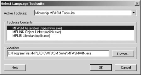
Figure 8-2 MPLAB Select Language Toolsuite Screen.
In the Select Language Toolsuite window, make sure that the file locations for all executables coincide with the actual installation path for the software. If in doubt, use the <Browse> button to navigate through the installation directories until the executable program is located. In Figure 8-2 the location of the mpasmwin.exe is shown. Follow the same process for all the executables in the Microchip MPASM Toolsuite window.
A more detailed control over the location of the various individual tools is provided by the Set Language Tools Location command, also in the Project menu. This command allows setting the installation path not only to the major suites, but also to the individual tools. Figure 8-3 shows the display screen of this command.
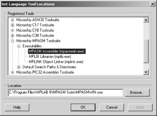
Figure 8-3 MPLAB Set Language Tools Location Screen.
In the MPLAB context, a project is a group of files generated or recognized by the IDE. Figure 8-4 shows the structure of an assembly language project.
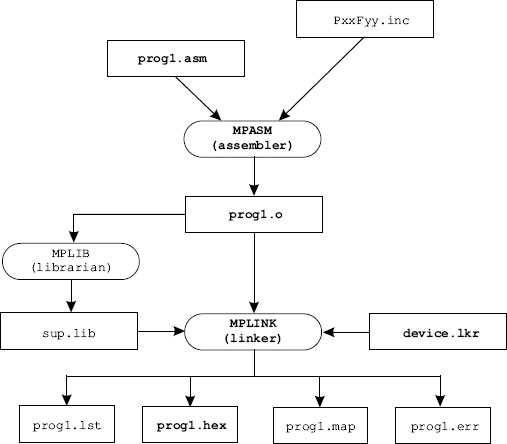
Figure 8-4 MPLAB Project Files.
In Figure 8-4 an assembly language source file (prog1.asm) and an optional processor-specific include file are used by the assembler program (MPASM) to produce an object file (prog1.o). Optionally, other sources and other include files may form part of the project. The resulting object file, as well as one or more optional libraries, and a device-specific script file (device.lkr), are then fed to the linker program (MPLINK), which generates a machine code file (prog1.hex) and several support files with listings, error reports, and map files. It is the .hex file that is used to blow the PIC.
In addition to the files in Figure 8-4, others may also be produced by the development environment according to the selected tools and options. For example, the assembler or the linker can generate a file with the extension .cod, which contains symbols and references used in debugging.
Projects can be created using the <New> command in the Project menu. The programmer then proceeds to configure the project manually and add to it the required files. An alternative option that simplifies creating a new project is to use the <Project Wizard> command in the Project menu. The Wizard will prompt for all the decisions and options that are required, as follows:
1. Device selection. Here the programmer selects the PIC hardware for the project, for example 16F84A.
2. Select Language Toolsuite. This screen is the same one shown in Figure 8-2. Its purpose is to make sure that the proper development tools and paths are active.
3. Next, the Wizard prompts the user for a project name and directory. It is possible to create a new directory at this time.
4. In the next step the user is given the option of adding existing files to the project and renaming these files if necessary. Because most projects reuse a template, an include file, or other preexisting resources, this can be a useful option.
5. Finally, the Wizard displays a summary of the project parameters. When the user clicks on the <Finish> button the project is created and programming can begin.
Figure 8-5 is the display of the final wizard screen.
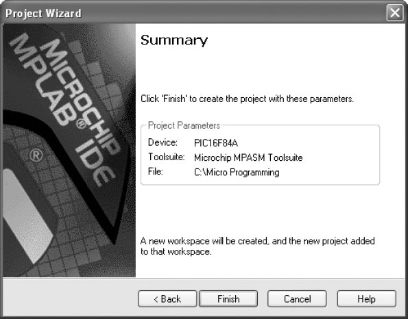
Figure 8-5 Final Screen of the Project Creation Wizard.
The <Build Options: Project> command in the Project menu allows the user to customize the development environment. Of the tabs available on the Build Options screen, the MPASM Assembler one is probably the most used. The screen is shown in Figure 8-6.
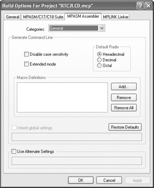
Figure 8-6 MPASM Assembler Tab in the Build Options Screen.
The MPASM Assembler tab allows performing the following customizations:
1. Disable/enable case sensitivity. Normally the assembler is case sensitive. Enabling this option turns all variables and labels to uppercase.
2. Select the Default Radix. Numbers without formatting codes are assumed to be hex, decimal, or octal according to the selected option.
3. The Macro Definition window allows adding macro directives. Macros are discussed later in this chapter.
4. The Use Alternate Settings textbox is provided for command line commands in non-GUI environments.
5. The Restore Defaults box turns off all custom configurations.
Once all the options have been selected, the installation checked, and the assembly language source file written or imported, the development environment can be made to build the project. Building consists of calling the assembler, the linker, and any other support program in order to generate the files shown in Figure 8-4 and any others that may result from a particular project or IDE configuration.
The build process is initiated by selecting the <Build All> command in the Project menu. Once the building concludes, a screen labeled Output is displayed showing the results of the build operation. If the build succeeded, the last line of the Output screen will show this result. Figure 8-7 shows the output screen after a successful build.
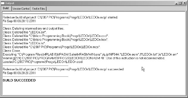
Figure 8-7 Output Window Showing the Build Command Result.
Very often during prototype development we need to create a single executable file without having to deal with the complexity of a full-fledged project. For this case, MPLAB provides the Quickbuild option in the Project menu. The resulting .hex file can be used to blow a PIC in the conventional manner and contains all the necessary debugging information.
We have used the Quickbuild option for most of the programs developed for this book. The typical command sequence for using the Quickbuild option is as follows:
1. Make sure the correct PIC device is selected by using the Configure>Select Device command.
2. Make sure the Quickbuild option is active by selecting Project>Set Active Project>None. This places the environment in the Quickbuild mode.
3. Open an existing assembly language file in the editor window using the File>Open command sequence. If creating a new program from scratch, use the File>New command to open the editor window and type in the assembly code. Then use the File>Save option to save the file with the .asm extension. In any case, the file must have the .asm extension.
4. Select Project>Quickbuild file.asm to assemble your application, where file.asm is the name of your active assembly file.
5. Your application can now be used to blow a PIC or to debug.
In the context of MPLAB documentation, the term debugger is reserved for hardware debuggers while the software versions are called simulators. Although this distinction is not always enforceable, we will abide by this terminology in order to avoid confusion. The reader should note that there are MPLAB functions in which the IDE considers a simulator as a debugger.
The MPLAB standard simulator is called MPLAB SIM. SIM is part of the Integrated Development Environment and can be selected at any time. The hardware debuggers offered by Microchip are named ICD 2, ICE 2000, and ICE 4000. A simulator, as the term implies, allows simulating the execution of a program one instruction at a time; also viewing file registers and symbols defined in the code. Debuggers, on the other hand, allow executing a program one step at a time or to a predefined breakpoint while the PIC is installed in the target system. This makes possible not only viewing the processor’s internals, but also testing the circuit components in real-time.
Microchip documentation describes the SIM program as a discrete-event simulator. SIM is part of the MPLAB IDE and is selected by clicking on the <Select Tool> command in the Debugger menu. The command offers several options, one of them being MPLAB SIM. Once the SIM program is selected, a special debug toolbar is displayed. The toolbar and its function is shown in Figure 8-8.
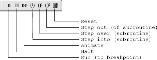
Figure 8-8 SIM Toolbar.
In order for the simulator to work, the program must first be successfully assembled. The most commonly used simulator method is single-stepping through the code and breakpoints. A breakpoint is a mark at a program line at which the simulator will stop and wait for user actions.
Breakpoints provide a way of inspecting program results at a particular place in the code. Single-stepping is executing the program one instruction at a time. The three buttons labeled <Step…> in Figure 8-8 are used in single-stepping. The first one allows breaking out of a subroutine or procedure. The second one is for bypassing a procedure or subroutine while in step mode. The third one single-steps into the program instruction that follows.
Breakpoints are set by double-clicking at the desired line while using the editor. The same action removes an existing breakpoint. Lines in which breakpoints have been placed are marked, on the left document margin, by a letter “B” enclosed in a red circle. Right-clicking while the cursor is on the program editor screen provides a context menu with several simulator-related commands. These include commands to set and clear breakpoints, to run to the cursor, and to set the program counter to the code location at the cursor.
The View menu contains several commands that provide useful features during program simulation and debugging. These include commands to program memory, file registers, EEPROM, and special function registers. One command in particular, named <Watch>, provides a way of inspecting the contents of FSRs and GPRs on the same screen. The <Watch> command displays a program window that contains reference to all file registers used by the program. The user then selects which registers to view and these are shown in the Watch window. The Watch window is shown in Figure 8-9.

Figure 8-9 Use of Watch Window in MPLAB SIM.
When the program is in the single-step mode or breakpoint mode, the contents of the various registers can be observed in the Watch window. Those that have changed because the last step or breakpoint are displayed in red. The user can click on the corresponding arrows on the Watch window to display all the symbols or registers. The <Add Symbol> or <Add FSR> button is then used to display the item on the Watch screen. Four different Watch windows can be enabled, labeled Watch 1 to Watch 4, at the bottom of the screen in Figure 8-9.
Another valuable tool available from the View menu is the one labeled <Simulator Trace>. The Simulator Trace window provides a view of the current machine instruction combined with a window that displays the source code. The Simulator Trace window is shown in Figure 8-10.

Figure 8-10 MPLAB SIM Simulator Trace Window.
8.3.2 MPLAB Hardware Debuggers
A more powerful and versatile debugging tool is a hardware debugger, sometimes called an in-circuit debugger. Hardware debuggers allow tracing, breakpointing, and single-stepping through code while the PIC is installed in the target circuit. The typical in-circuit debugger requires several hardware components, as shown in Figure 8-11.

Figure 8-11 Components of a Typical Hardware Debugger.
The emulator pod with power supply and communications cable provides the basic communications and functionality of the debugger. The communications line between the PC and the debugger can be an RS-232, a USB, or a parallel port line. The processor module fits into a slot at the front of the pod module. The processor is device specific and provides these functions to the debugger. A flex cable connects the processor module to an interchangeable device adapter that allows connecting to the several PICs supported by the system. The transition socket allows connecting the device adapter to the target hardware. A separate socket allows connecting logic probes to the debugger.
Microchip provides two models of their in-circuit hardware debuggers, which they call In Circuit Emulators, or ICE. The ICE 2000 is designed to work with most PICs of the mid-range and lower series, while the ICE 4000 is for the PIC18x high-end family of PICs. Recently Microchip has released an in-circuit debugger designated as ICD 2 that offers many of the features of its full-fledged in-circuit emulators at much reduced prices. One of the disadvantages of the ICD 2 system is that it requires the exclusive use of some hardware and software resources in the target. Furthermore, the ICD requires that the system be fully functional. The ICEs, on the other hand, provide memory and clock so that the processor can run code even if it is not connected to the application board.
The functionality of an actual hardware debugger can be replaced with a little ingenuity and a few lines of code. Most PICs are equipped with EEPROM memory. Programmers (covered in the following section) have the ability to read all the data stored in the PIC, including EEPROM. These two facts can be combined in order to obtain runtime information without resorting to a hardware debugger.
Suppose a defective application is suspect of not finding the expected value in a PIC port. The developer can write a few lines of code to store the port value on an EEPROM memory cell. An endless loop following this operation ensures that the stored value is not changed. Now the PIC is inserted in the circuit and the application executed. When the endless loop is reached, the PIC is removed from the circuit and placed back in the programmer. The value stored in EEPROM can now be inspected so as to determine the runtime state of the machine. In many cases this simple trick is less complicated and time consuming than setting up a hardware debugger, even if such a device is available.
In the context of microcontroller technology, a programmer is a device that allows transferring the program onto the chip. The process is called “burning” a PIC, or more commonly “blowing” a PIC. Most programmers have three components:
1. A software package that runs on the PC
2. A cable connecting the PC to the programmer
3. A programmer device
Dozens of PIC programmers are available on the Internet. By releasing the programming specifications of the PIC to the public without requiring a nondisclosure agreement, Microchip originated a “cottage industry.” The commercial programmers on the Internet range from a “no parts” PIC programmer that has been around because 1998, to sophisticated devices costing hundreds of dollars and providing many additional features and refinements. For the average new PIC user, a nice USB programmer with a ZIF socket and the required software can be purchased for about $50.00. Build-it-yourself versions are available for about half this amount.
An alternative programmer is made possible by the fact that some of the newer flash-based PICs can write to their own program memory. This allows placing a small bootloader program in PIC memory that will load an application over the RS-232 or USB lines.
Figure 8-12 is a screen capture of the driver software for a popular programmer from MicroPro.

Figure 8-12 Control Program for the DIY MicroPro Programmer.
The program developer’s main challenge is writing code that performs the task at hand. In this context this means writing a PIC assembly language program that assembles without errors (usually after some effort) and makes the circuit perform as intended. We have already reviewed the development environment (IDE) and the various hardware components and software tools. We now focus on the various elements that are used in developing the program itself.
One of the first realizations of novice programmers is how quickly we forget the reasoning and the logic that went into our code. It is common that a few weeks, even a few hours, after we coded a routine, we find that what was obvious then is now undecipherable and that the ideas that were clear in our minds a short time ago now evade our understanding. The only solution to the volatility of logic is to write good program comments that explain, not the elementary, but the trains of thought behind our code.
In PIC assembly language, the comment symbol is the semicolon (;). The presence of a semicolon indicates to the assembler that everything that follows, to the end of the line, must be ignored. Using comments judiciously and with good taste is the mark of the expert software engineer. Programs with few, cryptic, or confusing comments fall into the category of “spaghetti code.” In the programming lingo, “spaghetti code” refers to a coding style that cannot be deciphered or understood. The worst that can be said about one’s programming style is that one produces spaghetti code.
How we use comments to explain our code or even to decorate it is a matter of personal preference. However, there are certain common-sense rules that should always be considered:
• Do not use program comments to explain the programming language or reflect on the obvious.
• Abstain from humor in comments. Comedy has a place in the world but it is not in programs. By the same token, stay away from vulgarity, racist or sexist remarks, and anything that could be offensive. You can never anticipate who will read your code.
• Write short, clear, readable comments that explain how the program works. Decorate or embellish your code using ASCII graphics, according to your taste.
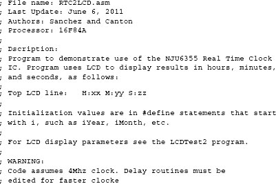
Every program should have a commented header that contains, at least, the following information:
• Program name
• Programmer’s or software company’s name
• Copyright notice, if pertinent
• Target device or hardware
• Development environment
• Development dates
• Program description
Some of these elements allow various levels of detail. For example, the target device can be a simple reference to the PIC for which the program is written, a more-or-less detailed description of the target system, or a reference to a circuit diagram or board drawing. The development environment can also be described briefly or in abundant detail. The dates entry can be a single item that lists the first or the last program change, or a detailed description of all program changes, tests, and updates. The program description can be a short sentence or a mini-manual on using the application. In any case, the level of detail and the contents of each category are determined by the programmer’s style, and the complexity and purpose of the application.
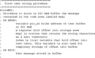
The following lines show the header of one of the programs developed for this book.
Very often we need to scroll through the code in search of a particular line or routine. Having banners that signal critical places in the program facilitate this search. Banners are created using comments and a framing symbol, as in the following code fragment:
Sometimes the programmer needs to emphasize a program area with a large banner that extends from margin to margin, as follows:

It is also possible to use comments to signal the function of bit fields and individual bits of an operand, as in the following code fragment:
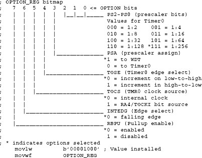
Clearly commented bitmaps, banners, and many other code embellishments do not add to the quality and functionality of the code. It is quite possible to write very sober and functional programs without using these gimmicks. The decision of how to comment and how much to decorate programs is one of style.
Most programs will require the use of general-purpose file registers. These registers are allocated to memory addresses reserved for this purpose in the PIC architecture. Because the areas at these memory locations are already reserved for use as GPRs, the program can access the location either by address or by assigning a name to the address. The equ (equate) directory performs this function, as follows:
var1 equ 0x0c ; Name var1 is assigned to location 0x0c
Actually the name (in this case var1) becomes an alias for the memory address to which it is linked. From that point on the program accesses the same variable. Program code can access the memory cell at address 0x0c as follows:
![]()
In addition to the equ directive, PIC assembly language recognizes the C-like #define directive, so the name assignation could have been done as follows:
#define var1 0x0c
Although named variables are to be preferred over hard-coded addresses, there are times when we need to access an internal element of some multi-byte structure. In these cases the hard-coded form could be convenient, although not absolutely necessary.
Another way of defining memory data is by using one of the data directives available in PIC assembly language. Although there are several of these, perhaps the most useful is the cblock directive. The cblock directive specifies an address for the first item and other items listed are allocated from this first address. The group ends with the endc directive. The following code fragment shows the use of the cblock/endc directives:
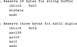
The cblock directive actually defines a group of constants that are assigned consecutive addresses in RAM. In the previous code fragment the allocation of 20 bytes for the buffer named strData is illusory because no memory is actually reserved. The illusion works because the second cblock starts at address 0x34, which is 20 bytes after strData; and also because the programmer will abstain from allocating other variables in the buffer space.
Having to deal with memory banks is one of the aggravations of PIC programming. Banks are designated starting with bank 0. All PICs of the mid-range family have at least two banks, so bank shifting operations are virtually unavoidable. The issue is more how to switch banks designated because there are several possible techniques.
Bank selection is by means of bit RP0 and RP1 in the STATUS register. In mid-range PICs with four banks the various combinations are as shown in Table 8.1.
Table 8.1
STATUS Register Bank Selection Bits
|
|
|
|
1 |
1 |
*Bank 3 |
0x180 - 0x1ff |
1 |
0 |
*Bank 2 |
0x100 - 0xx17f |
0 |
1 |
Bank 1 |
0x80 - 0xff |
0 |
0 |
Bank 0 |
0x00 - 0x7f |
* RP1 bit is not used in devices with two banks.
The most direct way to select the current bank is by clearing or setting the corresponding bits in the STATUS register. For example, to select bank 2 in a four-bank device, you could code:
bsf STATUS,6 ; Set bit 6 in STATUS register
bcf STATUS,5 ; Clear bit 5
Alternatively, the application can use the banksel directive which selects the bank in which a particular register is located. For example, to select the bank in which the ADCON1 register is located, code could be as follows:
banksel ADCON1
The banksel directive also works with registers defined by the user (GPRs).
An alternative way of performing bank selection is by coding bank select macros. A macro is an assembler structure that allows defining a series of instructions that is inserted in the code every time the macro is referenced. The PIC macro language defines the following format:
label macro [arg1, arg2… argn]
.
.
endm
In this example the ellipses serve as placeholders for PIC instructions, assembler directives, macro directives, or macro calls. Macros are usually defined at the beginning of the program because forward references to macros are not allowed. The optional arguments passed to the macro (arg1, arg2, etc.) are assigned values when the macro is invoked. For example, the following macros make the corresponding bank selections in a mid-range PIC with four banks:

Once the bank switching macros have been defined, the application can change banks simply by calling the macro name; for example, if we know that the ADCON1 register is in bank 1 we can select the bank by calling
Bank1
At this point in the code, the macro expansion will insert the corresponding operations to make the switch.
Which method to use when switching banks is a matter of personal preference and program constraints. Setting and clearing the RP1/RP0 bits is simple enough but can be error-prone. Using the banksel directive is convenient because we do not need to know in which bank the item is located. The objection to using banksel is that some unnecessary bank changes may take place. For example, if the program is already in bank 1 and the banksel directive appears with a register file in that same bank, then the bank switching code is generated anyway. The use of bank selection macros seems like a suitable method for most conditions. One advantage of the macro approach is that programs for different PICs can have their own banking macros. In this way code can be easily ported to different architectures.
Deprecated Banking Instructions
Several instructions in the mid-range instruction set have been deprecated and are no longer recommended by Microchip; these include tris and option. Microchip’s reason for not recommending these instructions is to maintain compatibility with future mid-range products. From a programmer’s viewpoint, it is difficult to see why using these instructions may be undesirable. In the unlikely case that our code will be ported to some other future device that does not support tris or option, then it will be easy enough to modify the code at that time.
The tris and option instructions are convenient because they allow loading the contents of the w register to the OPTION, TRISA, and TRISB registers directly, without bank concerns. For example, the following code fragment sets port line 1 to input and all others to output:
movlw b'00000010' ; Line 1 is input
tris PORTA
We continue to use the deprecated instructions in programs in which there is no concern about future consequences. In programs in which portability is an issue, we use the banking macros discussed previously.
8.5.4 Processor and Configuration Controls
PIC programs must define the processor to be used by the development software. The assembler processor directive (and also the list directive) allow defining the PIC type. For example, a program for the 16F877 would contain the following line:
processor 16f877
The PIC microcontrollers contain a special register called the configuration register that allows customizing certain processor features to the needs of the application. In the mid-range PICs, the bits in the configuration register are mapped in program memory location 0x2007. This memory location can only be accessed during the programming mode, so the bits cannot be changed during normal program operation. The configuration bits cannot be read at runtime.
Microchip recommends that the configuration bit be set by means of the __config directive. The bits are mapped as follows:
CP1:CP0: Code Protection bits
11 = Code protection off
10 = See device data sheet
01 = See device data sheet
00 = All memory is code protected
Some devices use more or less bits to determine the level of code protection. Some use a single bit for this purpose. In this case the encoding is as follows:
1 = Code protection off
0 = Code protection on
DP: Data EEPROM Memory Code Protection bit
1 = Code protection off
0 = Data EEPROM Memory is code protected
BODEN: Brown-out Reset Enable bit
1 = BOR enabled
0 = BOR disabled
Enabling Brown-out Reset automatically enables the Power-up Timer (PWRT) regardless of the value of bit PWRTE. Ensure that the Power-up Timer is enabled anytime that Brown-out Reset is enabled.
PWRTE: Power-up Timer Enable bit
1 = PWRT disabled
0 = PWRT enabled
MCLRE: MCLR Pin Function Select bit
1 = Pin’s function is MCLR
0 = Pin’s function is as a digital I/O.
MCLR is internally tied to VDD.
WDTE: Watchdog Timer Enable bit
1 = WDT enabled
0 = WDT disabled
FOSC1:FOSC0: Oscillator Selection bits
11 = RC oscillator
10 = HS oscillator
01 = XT oscillator
00 = LP oscillator
FOSC2:FOSC0: Oscillator Selection bits
111 = EXTRC oscillator, with CLKOUT
110 = EXTRC oscillator
101 = INTRC oscillator, with CLKOUT
100 = INTRC oscillator
011 = Reserved
010 = HS oscillator
001 = XT oscillator
000 = LP oscillator
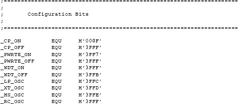
The __config directive is used to embed configuration data in the source file. Alternatively, the configuration bits can be set at the time the PIC is blown. The following code fragment shows setting the configuration bits for a 16F877 PIC:

One of the style issues that the programmer must decide concerns the conventions followed for program labels and variable (register) names. The MPLAB assembler is case sensitive by default, so PORTB and portb can refer to different registers.
The programmer can define all the registers (SFRs and GPRs) used by an application using equ or #define directives. A safer approach is to import an include file (.inc extension) furnished in the MPALB package for each different PIC. The include files have the names of all SFRs and bits used by a particular device. The following code fragment is a listing of the MPLAB include file for the 16f84a:
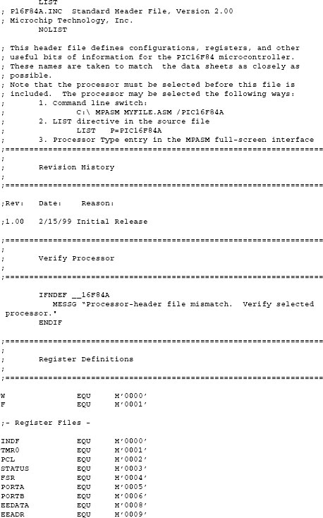
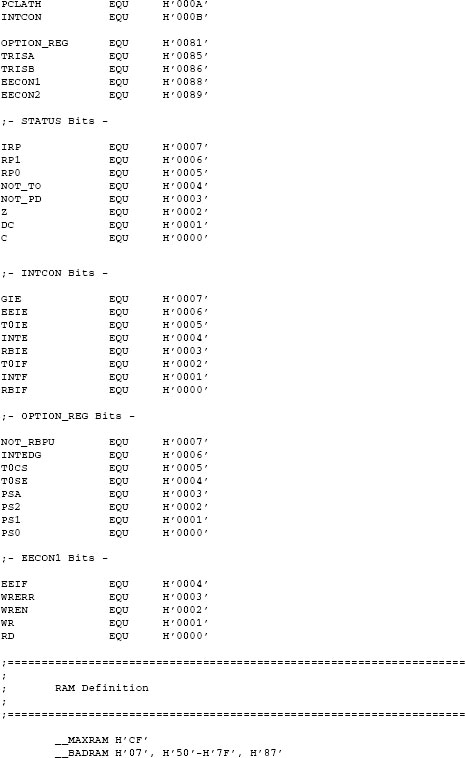
Note that all names in the include file are defined in all-capital letters. It is probably a good idea to adhere to this style instead of creating alternate names in lower case. The C-like #include directive is used to refer to the .inc files at assembly time; for example
#include <p16f84a.inc>
This directive allows controlling the warning and error messages produced at assembly and link times. One particular type of warning can be disturbing: those that refer to bank changes. Applications often turn off bank change-related warnings with the following line:
errorlevel -302
It is sometimes disturbing to read in a code listing instructions that are not part of the standard set for the particular device. The reason this happens is that MPLAB includes a set of pseudo instructions for 12- and 14-bit devices. A list of all supported pseudo instructions can be found in the MPLAB documentation. In our programming we prefer not to use them because they tend to make code less readable. Incidentally, Microchip also recommends not using the pseudo instructions.