
Chapter 4
Energy Reduction in Manufacturing via Incremental Forming and Surface Microtexturing
Jian Cao1* and Rajiv Malhotra2
1Department of Mechanical Engineering, Northwestern University, Evanston, IL, USA
2Department of Mechanical and Aerospace Engineering, Rutgers University, Piscataway, NJ, USA
*Corresponding author: [email protected]
Abstract
Energy reduction via manufacturing can be achieved in two ways. The first is the creation of new processes that inherently reduce energy consumption for fabrication of a part, as compared to existing processes. One such process, incremental forming, is a die-less sheet metal forming process that reduces the energy consumption for low volume batch production or rapid prototyping of sheet metal parts. The increased process flexibility, lower forming forces, and greater formability of the sheet metal have led to significant interest in this process in the last decade. The first part of this chapter (Section 4.1) will introduce the fundamentals of incremental forming including the general concept, geometric accuracy, surface finish, formability prediction, and energy consumption as compared to conventional forming processes. The second method for creating energy savings via manufacturing is to use manufacturing as an enabling technology. Surface microtexturing has been shown to result in energy savings by enabling reduced friction at moving interfaces and by prolonging tool life. The second part of this chapter, Section 4.2, will discuss these applications in detail and will describe laser ablation based and deformation based microtexturing techniques.
Keywords: Incremental forming, surface microtexturing, low volume production, rapid prototyping, friction
4.1 Incremental Forming
Incremental forming, in its simplest form, uses a hemispherical ended tool moving along a predefined toolpath to locally deform a completely peripherally clamped sheet of metal. The accumulative effect of the local deformations effected by the tool is to impart a desired global shape to the sheet. When only one tool is used, the process is called Single Point Incremental Forming or SPIF [1–3] (Figure 4.1a). The operational parameter ∆z in incremental forming is the step down in the negative Z direction in consecutive passes of the toolpath and is called the incremental depth. When two tools are used, one to support the sheet and the other to deform it the process is called Double Sided Incremental Forming or DSIF [4–7] (Figure 4.1b). The Incremental Forming process was recognized as a workable forming process in a very early patent by Leszak in 1967 [8]. The advances made in this process in the last ten years or so are now described, first in terms of the work done to quantify the energy savings in incremental forming as compared to conventional sheet forming processes, and then in terms of the technical issues and advances made to realize incremental forming as a viable industrial process.

Figure 4.1 Schematic of (a) Single point incremental forming (b) Double sided incremental forming.
4.1.1 Conventional Forming Processes
The motivation for investigating Incremental Forming arises from an emerging need for metal forming processes that are economically viable and sustainable from an energy point of view, for rapid prototyping and small volume production of sheet metal parts. Conventionally-used forming technologies for sheet metal forming suffer from the following drawbacks:
Part-specific tooling and large inventory space: The use of conventional forming processes like deep drawing or stamping for low volume production requires conventional tool and die sets. One issue with using conventional forming processes for small lot production and prototyping is the use of dedicated tooling, which is custom made to match the shape being formed. These tools are very expensive in terms of financial and energy costs, a cost that is offset only when they are used for mass production. Another issue with conventional forming processes with their part shape specific tool and die sets is that these tools are very bulky. To enable refabrication of a component at a later time these tools have to be stored, resulting in inventories that occupy large amounts of space and are very expensive to maintain.
Increased Lead Time for Product Development: In conventional sheet metal forming, the path from actual product design to mass production has an intermediate stage in which the tooling design is perfected and fabricated. This is done by designing the punch-die sets, fabricating them and performing test runs to evaluate the tooling performance. Depending on the results from the test runs, the tooling design and fabrication processes are repeated iteratively till the final optimum tool design is obtained. This strategy works well when batch production volumes are very high and the final designed tooling is repeatedly used over very long periods of time. However, for small batch production and rapid prototyping the tooling needs to be repeatedly changed over very short periods of time. Consequently, an iterative tooling design strategy increases the lead time from product design to actual production by months and sometimes years. Furthermore, this iterative tooling design methodology also results in significant energy wastage in the repeated fabrication of tooling.
Increased Part Weight and Joining Operations: In sheet metal forming, formability is the ability to deform the sheet into a desired shape without the sheet metal undergoing fracture. A consequence of lower formability in the sheet metal forming industry is that certain complex shapes cannot be formed in a single forming operation. A common way of resolving this issue is to use thicker sheets that do not fracture as quickly. However, this adds to the component weight, which adversely affects fuel efficiency in the automobile and aerospace industries. Another solution is to replace forming operations with machining operations, which leads to considerable wastage of material and energy required for recycling. For example, the adoption of this practice in the aerospace industry has been estimated to cause about 90% of the material being turned into scrap due to machining [10].
Another common solution is to make complex surfaces as separate components and join them together. This requires increased number of joining operations and time, which translates to increased costs and energy consumption. Furthermore, reduced formability in conventional forming processes requires the use of additional tooling like drawbeads, which results in about 10 to 25% of the sheet metal ending up as scrap [11]. The scrap sheet metal then needs to be recycled in order to be reused, which requires an additional energy input.
To solve these issues, a need has arisen to create new flexible and energy efficient forming processes that are characterized by:
- Tooling that is independent of the shape to be formed. The tooling should consume a minimum amount of material, energy and should be low cost and easy to make. Furthermore, it should not be bulky so that storage space required for inventory is minimized.
- Ability to go directly from CAD model to formed part. This concept has two aspects to it. The first aspect involves an inherent potential of the process to go from CAD model to formed part without an intermediate tooling design and fabrication stage. The other aspect involves the rapid estimation of optimum forming process parameters so that the inherent flexibility of the process is preserved.
- Greater formability than in conventional forming, as an inherent characteristic of the process so that part weight and joining operations can be reduced.
Recently, a significant amount of research has focused on developing new forming processes that meet the aforementioned requirements. These processes can be classified as mechanical tooling based and energy based (Figure 4.2). In mechanical tooling based forming, the sheet is deformed using tooling that comes into direct contact with the sheet. In energy based forming, the sheet is imparted a certain amount of energy, which causes it to deform into a desired shape. Mechanical tooling based forming can be further classified into adaptive tooling based and flexible media based processes.
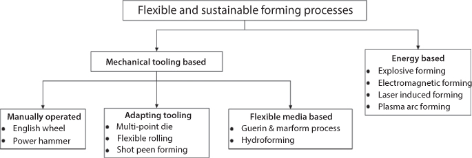
Figure 4.2 Classification of current flexible and sustainable forming processes.
Forming processes that use adaptive tooling include Multi-point Die (MPD) forming, flexible rolling and shot peen forming. In Multi-Point Die (MPD) forming [12] the die and punch in conventional forming processes (Figure 4.3a) are replaced with a controlled matrix of smaller modular pins, as shown in Figure 4.3b. Once the die and the punch are obtained by controlled motion of the individual pins the sheet metal is placed in between them and is formed. MPD alleviates the issue of material wastage in fabrication of shape-specific tooling by making the dies modular and reconfigurable. However, if the individual pins are placed too far apart they tend to bend and the stiffness of the formed die is not high enough. Placing the pins too close to each other results in the individual pins dragging each other along while moving during the alignment process, which results in an unintentional misalignment of the individual pins. Also, no significant increase in formability is observed as compared to conventional forming and the typical process capability window for MPD forming is shallow shapes with large in-plane areas.

Figure 4.3 Schematic of (a) Conventional stamping (b) MPD forming system
In flexible rolling [13], instead of using the rigid rollers typically used in conventional rolling, each roller is made of a flexible shaft of steel wire, the shape of which is controlled by individual pins attached at certain locations along the length of the roller (Figure 4.4). This variation of rolling is able to produce parts with double curved surfaces while maintaining the mass production nature of the conventional rolling process. However, deeper shapes cannot be formed due to restrictions on the geometric shapes that can be achieved with the rollers.
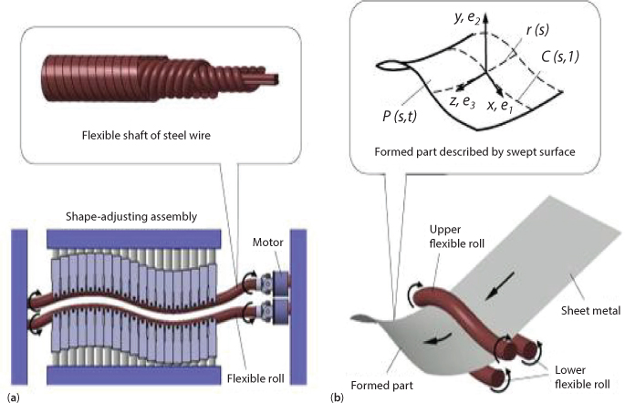
Figure 4.4 Schematic of (a) Flexible rolling setup (b) 3D view of flexible rolling process. [13].
Shot peen forming uses small shots or balls to locally impact the sheet at a certain velocity (Figure 4.5). The state of stress and the consequent bulging or sinking of the local region of the sheet depends on the shot velocity [14]. This process can produce features with both directions of curvature on the same sheet and the compressive effect suppresses the occurrence of fracture. However, shot peen forming is difficult to control because a relationship between the material properties of the blank, the speed of the balls and the resultant stress in the material must be found.

Figure 4.5 Schematic of shot peen forming process (http://abrasivefinishingcompany.com/t-peen-forming.html)
Another method to reduce tooling in forming operations is to replace the punch with a flexible medium like an elastomer [11], as shown in Figure 4.6a. However, at least one half of the conventional tooling is still required, which results in the tooling still being specific to the component shape being formed. When a fluid is used as the medium for transmitting pressure to the sheet the technique is called hydroforming [14], shown in Figure 4.6b. Since one half of the tooling is replaced by the liquid media, the tooling required is reduced. However, the process is limited by the very high clamping force required to seal the dies, especially for large panels and thick and hard to deform materials. Also, the wrinkling phenomenon present in conventional die forming is greater in hydroforming.
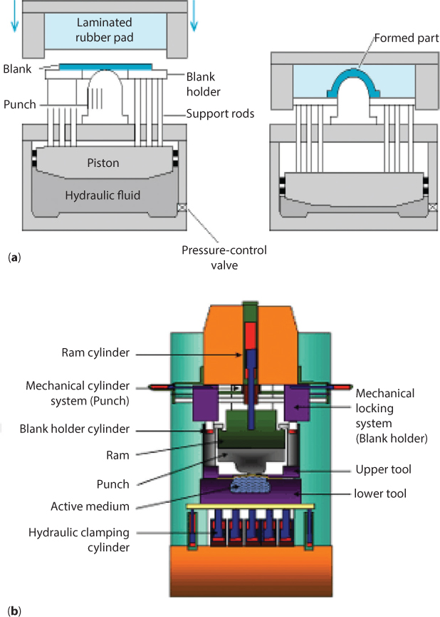
Figure 4.6 Schematic of (a) Marform process [11] and the (b) Hydroforming process (http://www.thefabricator.com).
Energy based forming processes impart energy to the sheet metal blank to force it into a die so that a desired shape is imparted to the sheet. Forms of energy based forming include the use of explosive energy (explosive forming, Figure 4.7a), electromagnetic energy (electromagnetic forming, Figure 4.7b) or energy supplied by heat (laser or plasma based forming). However, these processes still require dies to form the material, resulting in the process flexibility being reduced.

Figure 4.7 (a) Schematic of Explosive forming process.[15] (b) Schematic of Electromagnetic-die forming process.[15].
4.1.2 Energy Reduction via Incremental Forming
Incremental Forming is characterized by certain inherent features, which create the energy savings in the process. Some of these advantages are as follows:
- Part shape independent tooling: The tools used in Incremental Forming are simple and easy to make (Figure 4.8a).
- Increased formability: Formability is higher by about three times in Incremental Forming, as compared to conventional forming processes (Figure 4.8b).
- Reduced forming forces: Incremental Forming has lower forming forces than in conventional forming. This leads to lighter tooling and smaller and lighter machines. For example, the Incremental Forming machine shown in Figure 4.8d [7] has a smaller footprint and a lighter weight than a conventional forming press with the same forming area (Figure 4.8c).
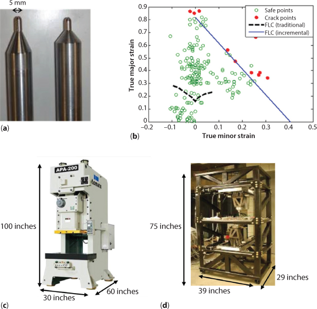
Figure 4.8 (a) Tools used in Incremental Forming (b) Experimental Forming Limit Curve for SPIF and conventional forming [19] (c) Conventional forming press, weight 8000 lbs (d) Incremental Forming machine, weight 2000 lbs.
The energy and environmental impact of Incremental Forming was investigated by a team comprising authors and researchers from MIT, Penn State and the Ford Motor Company [16]. Three different samples were made from aluminum and steel sheets by SPIF while forces, tool displacements and electric energy consumption were measured. Afterwards, similar measurements were conducted for DSIF in order to evaluate the performance of both forming modes. The concept of exergy analysis [17] was used to determine the process efficiencies of SPIF and DSIF and compared to sheet hydroforming and conventional forming with cast iron and plastic die sets. A second control volume was analyzed, aiming to investigate the impact of different forming technologies from a supply chain perspective. The system boundaries were drawn around the entire supply chain, enclosing all upstream activities that are related to the forming process and the material production. The results were used to relate the environmental impacts of incremental forming of sheets, hydroforming and conventional forming from a supply chain perspective. Since the input materials were mostly primary fuels, the analysis was comparable to a general embodied energy analysis. The supply chain was modeled with a newly developed Simulink blockset. Additionally, potential CO2 reductions were estimated.
The results of both analyses suggest that IF is environmentally advantageous for prototyping and small production runs, as indicated in Figure 4.9. The input exergy for DSIF, indicated by the dark dashed line, is less than the input exergy for the conventional forming with matched and reinforced plastic dies, less than that for the conventional forming using cast iron die sets, and less than that for hydroforming with a single reinforced plastic die. In addition, the sensitivity analysis of exergy calculation and the analysis of DSIF’s energy benefits compared to conventional sheet forming processes was conducted with respect to production volume. It was shown that even at very large number of produced parts (greater than 2,000), IF saves at least 5% of the energy used in conventional forming. The first exergy analysis also showed that the exergy of the material input dominated the electricity input from the control system for the DSIF. Particularly, the exergy of the sheet material contributed a significant fraction to the total exergy input.

Figure 4.9 Comparison of exergy consumption between Incremental Forming, hydroforming and conventional forming processes [9].
While the analysis provides solid evidence for energy productivity improvement of one example part using DSIF (ranging from 5% for large volume to as much as 350% for a production volume of 50 parts), the following analysis further examines the impact of Incremental Forming on two potential markets, i.e., automobile and aerospace industries [9].
The energy reductions associated with Incremental Forming come from four major sources: first, from the savings due to the elimination of stamping dies (E1); second, from the increased material utilization (less waste) due to the enhanced formability obtained from this process (E2); third, from the reduced energy consumption during the part distribution and use phase due to the lightweight structure (E3); fourth, from the newly added manufacturing efficiency (E4).
Additional potential advantages of Incremental Forming include:
- Shortened production time for sheet metal parts from 8 ~ 25 weeks to less than 1 week and satisfying the need for quick, high-quality sheet metal forming through a universal forming machine that eliminates the need of cast and machined dies used in traditional deep drawing, stretch forming, hydroforming or superplastic forming processes.
- Reduction in greenhouse gases by up to 1 million tons, which is equivalent to the total CO2 emission of 350,300 average mid-size passenger cars. These reductions are realized due to lightweighting and avoided forming dies and the avoided sheet metal use due to reduced waste.
- Direct economic benefits of up to $2.36 Billion [23] resulting from the saving of raw sheet metals, saving of die and lightweighting of sheet metal parts.
It is because of these advantages that Incremental Forming has generated significant interest as a potential candidate for further development as a flexible and sustainable sheet metal forming process. At the same time there are certain technical and scientific challenges that need to be addressed before Incremental Forming can reach its full potential. These challenges and the progress made in this regard are discussed next.
4.1.3 Challenges in Incremental Forming
As shown in the previous subsection Incremental Forming can make significant contributions to the sustainable and energy efficient manufacturing paradigm. However, for this potential to be fully realized, multiple requirements must be satisfied simultaneously (Figure 4.10). As in all forming processes, these requirements include forming a component with desired geometric accuracy and surface finish, and without sheet failure during the forming process. Additionally, the forming time should be minimized to ensure higher productivity. These requirements are tied up mainly to the toolpath planning and machine design in Incremental Forming. In this section we will discuss the major scientific and technical advances made in these areas.
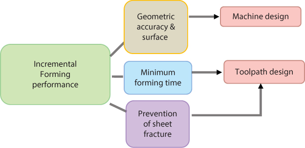
Figure 4.10 Schematic showing the technical challenges in incremental forming.
4.1.3.1 Toolpath Planning for Enhanced Geometric Accuracy and Process Flexibility
Single Point Incremental Forming SPIF is plagued by an inherent geometric inaccuracy due to the absence of a supporting die below the sheet, which does not allow the deformation to be concentrated into the desired area of contact with the forming tool. (Figure 4.11). Attempts have been made to resolve this issue. Allwood et al. [24] attempted to improve the geometric accuracy by using partially cut out blanks along the periphery of the forming area. The authors noted that this technique was not useful in improving geometric accuracy in IF, especially in comparison to the significantly better geometric accuracy provided by a partial support in spite of the resultant loss in process flexibility. Allwood et al. [25] also used closed-loop feedback control to improve the geometric accuracy in SPIF by forming the component in a second forming iteration. The need for iterative experiments to obtain set points for the control system increased the forming time for a given part, resulting in a loss of process flexibility in terms of being able to quickly change the part shape formed from one forming run to the next. Further, while the part accuracy obtained from the second forming iteration was better than the initial iteration, the reduction in unwanted bending outside the desired deformation region of the sheet was not significant enough to retain high geometric accuracy of the formed part.

Figure 4.11 Schematic showing geometrical inaccuracy in SPIF.
Tekkaya et al. [26] used generic sectional shapes to act as supports for the forming tool assisted with an analytical tool that calculates thinning to achieve a better geometric accuracy in SPIF. This strategy requires supporting shapes that are specific to the part geometry being formed. However, specific support shapes still need to be manufactured for different shapes, more so for complex automotive and aerospace shapes. Thus, replacing a single bottom die with multiple shaped supports does not mitigate the reduction in energy savings and loss in process flexibility that comes with the use of a bottom supporting die. The overall conclusion of the above works was that a supporting die or shape below the sheet is necessary to achieve high geometric accuracy of the formed part in SPIF. However, the use of a bottom die could significantly compromise the cost and energy savings described in Section 4.2.2.
This fundamental drawback of SPIF motivated the development of the Double Sided Incremental (DSIF) process, simultaneously by Meier et al. [4] and by the authors [6]. In its simplest form, DSIF uses one hemispherical ended tool on either side of the sheet, one tool acting as the forming tool and the other tool acting as the supporting or squeezing tool. The most intuitive kind of toolpath used in DSIF is the conventional out-to-in toolpath (shown for the forming of a simple cone in Figure 4.12a). In this toolpath, forming begins at the largest diameter of the cone and ends at the smallest diameter, while the tool travels simultaneously in the X, Y and Z directions. If a constant Incremental Forming depth (Δz) is used, by the third pass both tools will be at Z positions of -3Δz. The local angle generated at each deformation point is controlled by the position of the supporting (bottom) tool in relation to the forming (top) tool. As shown in Figure 4.13, the local wall angle θ is equal to the angle subtended to the vertical by the line segment OO’ connecting the centres of the two hemispherical tools. Therefore, the position of the bottom tool is calculated according to Equation 1.

Figure 4.12 Schematic showing toolpath in (a) DSIF out-to-in toolpath (b) ADSIF toolpath.

Figure 4.13 Schematic showing relative positioning of the top and the bottom tools.
where, ![]() = vector coordinate of the bottom tool centre,
= vector coordinate of the bottom tool centre, ![]() = vector coordinate of the top tool centre, R1, R2 = Radii of top and bottom tools, respectively,
= vector coordinate of the top tool centre, R1, R2 = Radii of top and bottom tools, respectively, ![]() = unit normal at the local contact point T (Figure 4.13). The distance d between the closest surfaces of the hemispherical tools is decided based on the sine law (Equation 2) and is essentially the desired thickness of the deformed wall. The constant s (≤1.0) decides the amount of squeezing that the sheet experiences.
= unit normal at the local contact point T (Figure 4.13). The distance d between the closest surfaces of the hemispherical tools is decided based on the sine law (Equation 2) and is essentially the desired thickness of the deformed wall. The constant s (≤1.0) decides the amount of squeezing that the sheet experiences.
where, t0 = original blank thickness.
The authors investigated the performance of the DSIF out-to-in toolpath in collaboration with researchers from the Ford Motor Company [7]. A simple conical component was formed such that the in-plane area of the part was much smaller than the in-plane size of the sheet. This was done so that the improved geometric accuracy, if any, as a consequence of the DSIF out-to-in toolpath could be easily compared to the geometric accuracy in SPIF. Experiments were performed on a DSIF machine built by the Ford Motor Company for this purpose. All components shown in Figure 4.14 were formed with s = 1.0, except when explicitly stated otherwise. It was observed that while the wall of the formed part was much more accurate with DSIF out-to-in than with SPIF, there was still a significant lack of accuracy on the part base (Figure 4.14b).
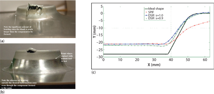
Figure 4.14 (a) Comparison of parts formed with SPIF and DSIF out-to-in toolpaths (b) Comparison of geometric profiles of parts formed with SPIF and DSIF out-to-in toolpaths.
An observation of the formed components showed that at some point during the forming process the supporting tool lost contact with the sheet, resulting in the process degenerating into SPIF. This caused the deformation to spread into the surrounding area of the flat part of the sheet and caused significant springback of the base after the forming was finished. This early work showed two possible sources of geometric inaccuracy of parts formed using DSIF, namely (1) loss of contact between sheet and bottom tool during forming (as above) due to finite compliance of the machine tool and the forming tool; and (2) process parameters and toolpath strategy used, including relative positioning of the DSIF tools.
Meier et al. [4, 5] used a DSIF machine tool with each tool mounted on a serial robotic manipulator to investigate DSIF. To compensate for finite machine compliance and maintain contact between the sheet and both forming tools in DSIF, the authors developed a strategy, based on in-line measurement of forming forces and multi-body modelling of the robots. As a result, the forming tool was displacement controlled and the supporting tool used a combination of displacement and force control to ensure contact between the supporting tool and the sheet at all times, leading to greater formability. However, a drawback of this strategy is that the amount of force to be applied and a preset angular offset for the supporting tool have to be worked out by repetitive trials every time the component shape is changed. Furthermore, depending on the global shape of the component the force required will change. Therefore, to form a freeform shape the amount of force required will vary spatially and will have to be predetermined by experimental iterations, causing a loss in process flexibility.
The Accumulative-DSIF or ADSIF strategy (Figure 4.12b, [7]) overcomes the above issues. Using ADSIF to form the same cone, the forming process begins from the smallest diameter and ends at the largest diameter of the cone. First, the forming and supporting tools form the material to a depth equal to the specified incremental depth Δz in the first pass. Then, in the second pass, both the forming tool and the supporting tool move outwards in the X-Y plane but maintain the same Z position. This second pass deforms the next outlying region of the material by Δz. Meanwhile, due to the rigid body movement, the region of the blank formed in the first pass is displaced down in the negative Z direction by an amount equal to Δz. Hence, the Z position of the component base after the second pass is -2Δz. Similarly, when the third pass is formed, the component base is at a Z position of -3Δz while both tools are still at a Z position of –Δz. The relative positioning between the tools is controlled by variables D and S (Figure 4.15).

Figure 4.15 Schematic showing relative positioning of forming tool (top tool) and supporting tool (bottom tool) in ADSIF.
In the ADSIF toolpath strategy both the tools are under displacement control and the toolpath is generated completely a priori from the CAD geometry of the part being formed. No part specific process planning is required to use this generic strategy, irrespective of the complexity of the part geometry. ADSIF is also able to consistently maintain contact between the tools and the sheet throughout the forming process, resulting in a significant enhancement of the process capabilities of DSIF. The geometric accuracy achieved with ADSIF is considerably better than that with the SPIF and out-to-in DSIF toolpaths (Figure 4.16). Additionally, the formability is significantly increased as well. For example, Figure 4.17a shows a 50° cone formed with ADSIF, DSIF out-to-in and SPIF. While the sheet fractures with SPIF and DSIF out-to-in toolpaths, the ADSIF strategy is able to form the part without failure of the sheet. Also ADSIF can be used to form complex freeform and concavo-convex components with features on both sides of the sheet in one single setup (Figure 4.17b), i.e., without flipping the sheet.
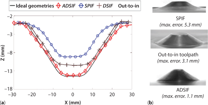
Figure 4.16 (a) Comparison of profiles of a 40° wall angle cone formed with SPIF, DSIF out-to-in and ADSIF toolpaths (b) Comparison of parts formed with SPIF, DSIF out-to-in and ADSIF toolpaths.

Figure 4.17 (a) 50° wall angle cone that fractures with SPIF and DSIF out-to-in toolpaths but not with the ADSIF toolpaths (b) Complex parts formed with ADSIF.
The ADSIF and out-to-in DSIF toolpath methodologies were implemented on a custom designed and custom-built gantry type Incremental Forming machine (Figure 4.18). The design is based on a system in which both the X and Y axes on each side of the sheet clamping fixture are on double gantries, i.e., each of the X and Y axes move on two linear guides. Each linear guide is individually controlled by its own separate motor. A double gantry system is used instead of a single gantry because in a single gantry system the moments on the forming tool will cause twisting of the X and Y axes structures. Both the linear guides for any axes on the double gantry system are actively actuated instead of having a master-follower system to ensure that one guide does not get stuck. The use of two actively actuated linear guides requires that the motion of the two motors for each axis be coordinated. This is enabled by a Delta-Tau control system, which is used to control both the motion of both tools simultaneously. For further details on the machine design, refer to [27].

Figure 4.18 Custom built Incremental Forming Machine at Northwestern University.

Figure 4.19 Comparison of tool z forces between FEA and experiments for (a) 70° cone shape (b) funnel shape.
The greater formability and geometric accuracy in ADSIF provide significant advantages over conventional DSIF toolpath strategies. However, a key issue with ADSIF is the need to use small incremental depths and therefore longer forming times to prevent issues with geometric accuracy of the formed part. It is likely that the use of larger incremental depths in ADSIF, resulting in correspondingly greater forming forces, causes greater deflection of the machine tool which results in poor geometric accuracy. Note that this phenomenon is again related to the machine compliance.
The above early development of the DSIF process, and demonstration of its advantages as compared to SPIF, has led to an increased focus on DSIF rather than SPIF. Reddy et al. [28] worked on compensating for loss of tool-sheet contact in conventional DSIF by accounting for the deflection of the tool due to the forming forces and local elastic springback of the sheet. The developed strategy was implemented on a custom built DSIF machine and was able to minimize loss of contact between the bottom tool and the sheet during DSIF. The gantry type DSIF machine tool used in this work was quite stiff in itself, so that the source of finite compliance was primarily from the forming tool used. In DSIF machines where this is not the case, the compliance of the tool and the machine as a whole have been measured and included within finite element simulations of the DSIF process [29] to create compensated DSIF toolpaths. Another approach to obviating the need for such compliance compensation has been from a machine design point of view. Both serial [4, 5] and gantry type [7, 28] DSIF machines have been developed in the past. It is worth noting that while such machine architectures have a workspace that is spatially more uniform, their spatial stiffness characteristics can be much poorer than those of parallel architecture machines. Further, the push towards commercialization of DSIF means that the machines and the forming area need to be larger. This accentuates the stiffness issues in serial and gantry type machines, which are typically less stiff as one moves away from the centre of the forming area. There are ongoing efforts to design highly stiff DSIF machines with meter sized sheet forming areas based on parallel manipulators [30]. By accounting for the uniquely local nature of deformation and forming forces in in DSIF, such machines might be able to minimize the need for compliance compensation in DSIF.
The relative positioning of the tools in DSIF also influences the geometry of the formed part by affecting the relative degree of squeezing and bending of the sheet in the local region of the sheet that is being deformed by the two tools. Choosing the tool positioning strategy via trial-and-error experiments can severely compromise the process flexibility of DSIF, especially for complex shapes with spatially varying wall angles. Finite Element Analysis of DSIF has been used to show that the effect of tool positioning can be quantified in terms of two positioning parameters. These parameters are a position angle (θ) which is the angle between the vertical direction and the line connecting the centers of the forming tool and the supporting tool, and the normalized tool gap (Tg) which is defined as the minimum distance between the two tools divided by the initial sheet thickness [31]. The change in the formed wall angle due to variations in θ and Tg showed that the design space can be divided into three different regions, i.e., squeezing-dominant region, bending-dominant region and competing region. When Tg is small (≤0.7), i.e., the squeezing-dominant region, the wall angle is primarily dependent on squeezing of the sheet between the tools and therefore on Tg. When Tg is larger than 1, i.e., the bending-dominant region, the deformation and the final geometric shape are dominated by bending and stretching instead of squeezing. When 0.7≤Tg≤1.0, i.e., in the competing region, both Tg and θ influence the final geometry. If θ and Tg are in the squeezing-dominant region, a smaller θ is preferable. With the increase in θ, the supporting tool overbends the material, and then both tools squeeze the sheet. In the competing region and squeezing-dominant region, forming forces are increased dramatically when Tg is decreased. However, the large force due to a small Tg can induce a local instability in forming process. In order to minimize the forming force, θ and Tg in the bending-dominant region or competing region are preferable. These fundamental observations were further extended [32] by combining Finite Element Analysis of DSIF with Gaussian Process Modelling to account for the deformation mechanics in DSIF and compliance of the DSIF machine. This enabled a priori prediction of the optimum tool positioning for maximization of geometric accuracy in DSIF. As a result, it is now possible to not only pick the ideal positioning parameters for a given sheet material, but simultaneously account for the stiffness of the DSIF machine being used as well.
Another interesting approach to increasing geometric accuracy of the DSIF formed parts has been the use of a mixed toolpath strategy. The concept behind a mixed toolpath DSIF (or MDSIF) is to use ADSIF to attain a global geometric definition of the desired part and then perform another forming pass using an out-to-in DSIF toolpath to retain the desired local accuracy of the part, without ever removing the part from the machine. It has been shown [33] that MDSIF can improve the part accuracy as compared to pure DSIF and ADSIF toolpaths, while reducing the forming time necessitated by the need for a small incremental depth in ADSIF. At the same time, there is a need to optimize the toolpath positioning parameters and the incremental depths used in the ADSIF and out-to-in DSIF portions of this MDSIF strategy. Further, the effects of tool deflection and machine compliance need to be accounted for as well. Nevertheless, this is a promising approach to retaining desired geometric accuracy in DSIF.
4.1.3.2 Formability Prediction and Deformation Mechanics
Higher formability in Incremental Forming provides the opportunity to realize lightweighting of sheet metal parts and save energy via increased fuel efficiency. However, it is necessary to predict the sheet formability in the process for industrialization of the process to be possible. Underestimation of the formability will not let the full potential of lightweighting be utilized. Overestimating the formability will result in part failure during the forming process itself. Furthermore, a priori prediction of formability in Incremental Forming poses a challenge due to the unique deformation mechanics in the process which does not let conventional methods of formability analysis be usable. In this section we will discuss work done on formability prediction in SPIF followed by a comparison of the mechanics of failure between conventional forming and SPIF.
Early work in SPIF [1] indicated that the maximum formable wall angle could be a good indicator for material formability in SPIF. More recently, Hussain et al. [34] formed axisymmetric funnel shapes in which the profiles of the components were arcs of different radii of curvature and showed that the maximum formable wall angle depended on the radius of the curvature of the funnel component’s profile. This indicates that formability in SPIF depends on a combination of the global shape of the component and the process parameters, and therefore essentially on the deformation mechanics of the process. Filice et al. [35] explored the possibility of detecting fracture in real time based on the trend of the forming force. Szekers et al. [36] showed that this methodology works for a cone shape but not for a pyramid shape. This observation again highlights the fact that sheet failure in SPIF depends significantly on the process mechanics. Emmens et al. [37] proposed that while bending, shear, cyclic straining and hydrostatic stress are the dominant deformation mechanisms in SPIF, pinpointing which factors are primarily responsible for failure is difficult. Jackson et al. [38] showed experimentally that deformation in SPIF consists primarily of stretching perpendicular to the toolpath and through-the-thickness shear perpendicular to and along the direction of the toolpath. They also remarked that stretching in the direction perpendicular to the tool, increasing shear in a direction perpendicular to the tool and a localization of deformation were observed in their experiments and could be generalized to other Incremental Forming processes. While understanding and controlling forming forces and sheet failure in SPIF is important, another interesting challenge is to understand why SPIF results in a much higher formability compared to conventional forming processes. In this regard, an important experimental work performed by Allwood et al. [39] showed that the through-the-thickness shear in SPIF is much greater than in conventional forming processes. The question then arises: how does the combined application of tension, compression and shear in SPIF affect the formability in the process? Furthermore, how does this difference in deformation mechanisms from conventional forming translate into increased formability in SPIF.
Attempts have been made to use conventional Forming Limit Curves (FLCs) to characterize formability in SPIF. However, Emmens et al. [40] showed that FLCs have certain drawbacks when it comes to predicting failure in SPIF. It is known that FLCs are not valid when there is bending and through-the-thickness shear, both of which are significant in SPIF. As a result modifications of conventional FLCs by incorporating the effects of changing strain paths [41] and the effects of large normal contact pressures [42] would still not be able to predict failure in SPIF accurately. Silva et al. [43] developed an analytical membrane-based model to estimate stresses in the sheet, and to predict sheet fracture based on hydrostatic pressure based fracture models during SPIF. While this approach provided an elegant and computationally efficient method for gaining some insight into the deformation mechanisms in the process, it did not account for the significant shear deformation of the sheet in SPIF. Further, it could not account for certain experimentally observed phenomena such as the reduction in formability with increasing incremental depth.
Numerical investigations using finite element analysis (FEA) have been conducted to investigate the deformation forces and mechanisms in SPIF. Cerro at al. [44] simulated SPIF of a pyramid with a 75° wall angle with shell elements and obtained a 5% difference between the maximum values of the measured and calculated tool z forces. However, no attempt was made to predict fracture. Van Bael et al. [45] extended a Marciniak-Kuczyisnki analysis (M-K analysis) to predict localized necking and fracture in SPIF. However, the formability was underestimated since only sheet localization was considered, not actual fracture. Huang et al. [46] used Oyane’s criterion, an empirical fracture criterion, to predict failure during forming of a conical cup using SPIF. Although the model was found to capture forming limits in SPIF reasonably well, the predictions of forming forces were not satisfactory. A continuum damage based fracture model was used to capture failure of the sheet during SPIF [47]. In this model, damage accumulation depends on the both hydrostatic pressure and shear imposed by the tool on the sheet [48]. The occurrence of diffused necking and localized necking in the sheet was modeled as well as in [49]. A more complete description of the material model and the modeling method used can be found in [47].
To explain the increased formability in SPIF as compared to conventional forming, the occurrence of diffused and localized necking in SPIF and in conventional forming were compared. Figures 4.20 and 4.21 show the localization contours, z depths and plastic strains for the punch forming case and SPIF, respectively. In the localization flag contour plots, the localization flag has a value of 1.0 (blue colour or dark band) when the material is in a diffused necking state and a value of 3.0 (red colour or light band) when the material has reached a localized necking state (i.e., local shear bands have formed). In both figures the contours shown in (a) are at the onset of diffused necking, in (b) are at the onset of localized necking and in (c) are just before fracture occurs. The regions with diffused and localized necking are marked as ‘D’ and ‘L,’ respectively. Figures 4.20 and 4.21 show that diffused necking and localized necking in SPIF start out much earlier, which can be attributed to the faster damage accumulation in the process. However, the localized necking region does not transition to actual fracture as quickly in SPIF as it does in the punch forming case. This phenomenon can be better understood by a simple analogy; i.e., the so called ‘noodle’ theory, which is as follows: Consider a single string of noodles that is held at one end and then needs to be stretched as much as possible. One obvious strategy is to start pulling at the free end of the string (Figure 4.22a). As a result, at some location on the string the material will begin to localize, as shown in red vertical stripes in Figure 4.22b, a strain concentration will develop and eventually fracture will occur (Figure 4.22c). This is similar to what happens in conventional forming.
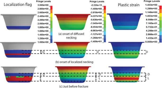
Figure 4.20 Contours of localization flag, z depth and plastic strain at (a) at onset of diffused necking (b) at onset of localized necking (c) just before fracture, for punch forming of the 70° cone.
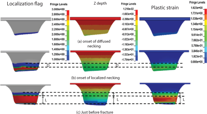
Figure 4.21 Contours of localization flag, z depth and plastic strain at (a) at onset of diffused necking (b) at onset of localized necking (c) just before fracture, for SPIF of the 70° cone.
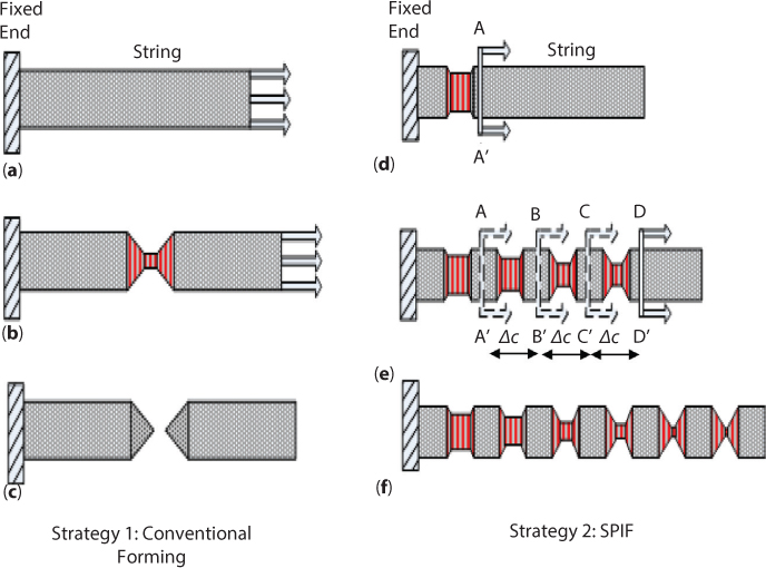
Figure 4.22 (a) Stretching the string at the free end (b) material localization at a single location on the string (c) Fracture at location of material localization (d) Stretching the string by ∆s at location ∆c from the free end (e) Continuous material localization along length of the string (f) elongation to a greater length without fracture.
An alternate strategy would be to stretch by smaller increments all along the string. One would start at a point a little bit away from the fixed end of the string (section AA’ in Figure 4.22d) and stretch by a small increment (say ∆s), while moving the location at which the deformation is applied by small regular increments (say ∆c) towards the free end of the string (Figure 4.22e), i.e., from section AA’ to DD’. In this case, material instability would begin much earlier as compared to the previous strategy (Figure 4.22d). However, if ∆s is low enough the localized material would not go all the way to fracture. So after some time, when the string is being stretched at section DD’ (Figure 4.22e), some of the deformation would be taken up by the previously localized region, i.e., at sections AA’, BB’ and CC’. As a result, the strain would get distributed more uniformly along the entire length of the string. With the right combination of ∆c and ∆s at each section the string could be stretched to a greater length without breaking (Figure 4.22f). This is very similar to what happens in SPIF. Note that the ability of a local shear band to share some of the subsequent deformation without going to fracture depends not only on the extent of the deformation but also on the location of application of the deformation. In the schematic representation of the “noodle” theory shown in Figure 4.22(e–f), for the SPIF strategy, the localized neck growth is more in the region near the actual section of load application. This is because as the distance of the neck from the actual point of load application increases, the ability of this neck to share some of the deformation decreases. As a result, after the onset of localized necking, it is always the neck closest to the contact zone that grows to fracture.
The existence of a larger localized region in SPIF is further supported by the observation of material localization all along the outer surface of the formed SPIF components (Figure 4.23). The components shown are funnels formed with an incremental depth of 0.5 mm. The z depth between the localized bands was measured using a depth gauge to be approximately 0.5 mm. Furthermore, it was visually observed during the forming process that these shear bands initiated and grew in the regions where the tool was currently in contact with the sheet. Fracture always occurred at a previously generated shear band closest to the current position of the tool. To summarize, the increased formability in SPIF, despite the higher damage accumulation in the process, is mainly due to the fact that the continuous motion of the tool away from the previously deformed region of the sheet does not allow the previously created shear bands to grow to fracture. This lets the sheet be deformed to a greater plastic strain than in conventional forming.

Figure 4.23 Regions along the outer surface of SPIF components indicating material localization.
While the above investigations resulted in new insight into the deformation and fracture mechanisms in SPIF, the development of DSIF (described in the previous section) created interest in understanding the sheet deformation in DSIF. Finite element analysis, with an experimentally obtained stress-strain curve for the sheet metal, was used to compare sheet deformation modes in ADSIF and SPIF. A detailed analysis of the deformation history obtained from FEA [50] showed that the sheet deformation behavior during ADSIF in its entirety is much different from that in SPIF. ADSIF is characterized by a bending-unbending nature of deformation along with squeezing of the sheet. The deformation of a particular region of the sheet can be decomposed into three stages of contact. In the first stage, a particular section of the material is in contact with one tool, i.e., the bottom tool. In this stage, the bottom tool supports and pushes the sheet in the positive Z-direction. In the second stage, the material is in contact with both the top and bottom tools simultaneously, which corresponds to the primary stage of deformation in the process where the sheet is being squeezed between both tools to form the sheet into the desired shape. Subsequently, in the third stage, the material is again in contact with just one tool, which is generally the top tool, but, under certain conditions, the contact could be between the sheet and the bottom tool. In SPIF, there is only one stage of contact, which corresponds to the tool being in contact with a given section of the material. ADSIF also causes the sheet metal to be subjected to greater plastic strains, through-the-thickness shear strains and greater hydrostatic pressure than SPIF. The primary cause for this is the highly localized nature of deformation in ADSIF as well as the presence of the additional supporting tool. It was also concluded that the higher hydrostatic pressure and through-the-thickness shear are quite likely the primary reasons for increased formability in ADSIF.
A key issue in using finite element analysis for modeling any form of DSIF, or for that matter SPIF, is the high computational effort and long simulation time. While the forming process itself takes a few hours, the simulation of the process takes a few days. This hinders the ability to leverage knowledge of the deformation mechanics of the sheet for rapidly iterative and a priori toolpath optimization. To overcome this issue a reduced-scale finite element analysis was developed by utilizing fully integrated shell elements with a thickness degree of freedom. This thickness degree of freedom is particularly important in DSIF due to the significant through-the-thickness shear and compression of the sheet during deformation [50]. This model was able to simulate the forming of an axisymmetric funnel part in only 23 hours as compared to a time of around 72 hours with a conventional FEA model that used multiple solid elements in the thickness of the sheet. The predicted and experimentally measured thicknesses and strains in the formed part were found to match well.
Another approach to significantly reducing computational time has been the use of analytical methods to analyze the stress state in the sheet during DSIF. A membrane-based method was employed to analyze the deformation of the sheet, based on the assumptions that the circumferential shear dominated over other shear mechanisms and that the radial stress component was independent of the wall angle of the part [51]. It was shown that the relative tool position and the force exerted by the bottom tool in the DSIF process effects the stress state in the material. Increasing the supporting force from the bottom tool without changing the relative position of the two tools can enhance formability due to greater pressure on the sheet. However, the experimentally observed reduction in formability under excessive pressure from the bottom tool could not be captured by this model. This study also suggested that repeated and reversible bending of the sheet under the simultaneous application of a tensile stress is responsible for higher sheet formability, except when high bottom tool pressure results in greater squeezing effect and compression begins to dominate the sheet deformation. This analytical approach provides a quicker estimation of stress-strain evolution in DSIF as compared to a full FEA analysis, but this approach still has limitations. For example, the effect of kinematic hardening due to repeated deformation of a material point and the prediction of fracture for complicated geometries is difficult with this model.
Further, note that none of the above models explicitly predict the occurrence of sheet fracture during DSIF. Rather the reasons for increased formability are hypothesized based on the deformation mechanisms observed. Predicting fracture of the sheet in a computationally efficient manner is still an area of active research.
4.1.3.3 Process Innovation and Materials Capability in DSIF
The highly local nature of deformation in DSIF has also given rise to the possibility of heating the local deformation area of the sheet metal to reduce forming forces, especially for magnesium and titanium alloys. One such process, Electrically Assisted DSIF or EADSIF, uses electrical current passing through the two tools to affect this heating of the local deformation zone of the sheet. Preliminary investigations in EADSIF showed issues related to sparking between the tool and sheet, as a well as excessive softening and cracking of the sheet metal due to very high current values. More recent work [52–54] has shown that the use of ADSIF and MDSIF toolpath strategies, or toolpath compensation for finite machine compliance, to retain tool sheet contact at all times can eliminate sparking between the tool and the sheet. While EADSIF can reduce the forming forces, there is a cutoff current value above which undesirable thermal effects mitigate this advantage. EADSIF can also enhance the geometric accuracy of the formed part. At the same time, Joule heating induced thermal softening of the sheet metal around surface defects can induce early fracture or future fatigue failure of the sheet metal. Further, depending on the magnitude of the electrical current used EADSIF can have a detrimental effect on the surface roughness of the formed part. A critical factor that has emerged from these investigations is that retaining contact between the tool and sheet is critical to preventing sparking between the tool and the sheet in EADSIF. Further note that the above advantages and disadvantages of EADSIF depend significantly on the current values and the toolpaths used in DSIF.
The expansion of the material capability of incremental forming beyond metals, specifically for forming thermoplastic sheets, has also been investigated. In one of the first investigations of this process Franzen et al. [55] experimentally examined the feasibility of forming polyvinyl chloride (PVC) sheets using SPIF. They reported three possible failure modes of the sheet, namely (1) Tearing of the sheet along the circumferential direction at the transition between the wall and the corner radius of the formed wall; (2) Wrinkling of the sheet along the circumferential direction of the part; and (3) Tearing of the sheet in the radial direction along the wall of the part. The authors also observed stress whitening in the formed PVC, probably due to deformation-induced crazing in the polymer. This materials capability was further expanded [56–57] for different thermoplastic polymers with varying degrees of crystallinity, including commodity thermoplastics such as polycarbonate, engineering polymers such as PEEK, and even biopolymers such as PLA.
From an applications point of view thermoplastic surfaces are widely used in packaging and in the interiors of automobiles and airplanes. One of the key reasons for using thermoplastic surfaces in the transportation sector is that thermoplastics are more amenable to meeting fire safety standards in the automotive and aerospace industries than thermosets [58]. A key point to note is that the deformation of the polymer in SPIF can be performed without the supply of any external heat to the process. Currently, thermoplastic surfaces for prototyping and replacement and for low volume fabrication in the above applications [59] are typically fabricated via injection-molding or hot forming. The absence of externally supplied heat resulting in thermal energy cost and the use of part-shape-independent tooling in polymer incremental forming, along with the demonstration of the above feasibility of the process, creates significant potential to reduce the manufacturing costs in the above applications.
Additional work has been performed to quantify the effects of the process parameters in polymer SPIF, key observations from which are now discussed. It was observed [57] that unlike metal, SPIF greater ∆z increases the formability of the polymer sheet in the tearing mode of failure. However, too large an incremental depth or too high a tool rotation speed causes a change in the mode of failure from tearing to wrinkling. Increasing the tool rotation speed during SPIF results in higher sheet temperatures during forming, which can increase the sheet temperatures beyond the glass transition temperature of the polymer, thus reducing the forming forces and increasing the formability [60]. Investigations into the properties of the formed polymer material have shown that significant anisotropy is induced in the formed polymer after deformation, with greater yield stress along the meridional direction and lesser yield stress along the circumferential direction [61]. Further, the formed material has greater toughness and ductility as compared to the unformed material due to greater orientation of polymer chains induced by the deformation of the sheet during polymer SPIF [62]. A more recent study has explored DSIF of polymers, for the first time, and shown that DSIF results in greater formability, lesser void growth in the polymer, and improved geometric accuracy as compared to SPIF[63].
There have been attempts to theoretically predict stress-strain evolution in polymer SPIF as well. These models have primarily accounted for a hydrostatic pressure-dependent yield stress [61–64] and have obtained reasonable predictions of the strain in the polymer sheet during SPIF. Experimentally derived fracture forming diagrams have also been used to predict fracture limits in SPIF. Yonan et al. [65] used a simplified material finite strain non-linear visco-plastic model for the polymer material to model polymer SPIF within a FEA framework. They were able to qualitatively capture the experimentally observed evolution of strain and forming forces as a function of the incremental depth and the shape of the formed part. At the same time this model overestimated the material response and thickness reduction for combined bending-shear modes with greater thickness of the sheet. One of the reasons for this behavior of the model might have been the assumption that softening and strain hardening after necking were negligible. This is because polymers behave significantly differently from metals, in that strain localization leads to further hardening after an initial softening stage, and because polymer SPIF is a highly local room temperature deformation process in which such strain localization is quite likely. At the same time there is significant further work to be done in modeling polymer SPIF in terms of predicting and understanding sheet wrinkling; modeling of semicrystalline polymers, which can behave very differently than amorphous polymers; and most importantly, extending these modeling efforts towards understanding the deformation mechanisms in polymer DSIF. It should be noted that both EADSIF and polymer incremental forming are currently active research topics.
4.1.3.4 Future Challenges in Incremental Forming
Overall, significant progress has been made in incremental forming in the last decade. The onus of research and development in this area has shifted from the basic SPIF process to the more advanced DSIF process in terms of understanding and controlling the process behavior and creating better and larger industrially relevant machines for commercialization of the process. Along with fundamental research the possibility of using DSIF to form parts for automotive, aerospace, [66] and biomedical [67] applications has been demonstrated. At the same time there are still key gaps that need to be bridged.
A priori predictive models that explicitly capture sheet fracture during metals DSIF need to be developed. A concurrent challenge is to ensure that these modelling methods are computationally fast enough to allow rapid iterative optimization of DSIF toolpaths for simultaneously preventing fracture and retaining desired geometric accuracy of the formed part. Creating this efficient link between toolpath planning and deformation mechanics is one of the grand challenges in incremental forming. It is likely that metamodeling-based frameworks will be useful for creating this link, with input from FEA predictions of fracture and geometric accuracy as a function of the toolpath parameters. The modification of analytical modelling methods based on observations from FEA, and the use of the predictions of sheet failure and geometric accuracy from these analytical models in metamodeling frameworks, may further reduce the time required to compute optimum DSIF toolpaths.
Another issue, which has been largely unexplored, is the operational performance of the parts formed with incremental forming. Evaluation of the mechanical properties of incrementally formed material is critical to ensure that the advantages created by reduced energy consumption are not negated by a reduction in part performance. Since the sheet metal does not flow into the deformed zone during the forming process it is expected that the deformation and sheet material thinning is more severe than in conventional forming. This should cause incrementally formed components to have a lower operational life than conventionally formed ones. At the same time, the plastic strain gets concentrated very highly into a local zone in conventional forming, as shown in Section 4.2.3.2. This can cause stress concentrations and earlier failure of the conventionally formed part during actual operation. In contrast, the deformation is much more uniformly distributed in incremental forming than in conventional forming (Section 4.2.3.2). Preliminary investigations [68] have shown that the sheet metal formed with DSIF has greater fatigue life than the virgin material. However, there is a need to further characterize the complete mechanical performance of the material as a function of the toolpath parameters and toolpath strategy used in DSIF. Subsequently, prediction of the mechanical properties and inclusion of this property of the formed material into a priori toolpath optimization methods is also required.
An even greater, but highly impactful, challenge is to compute toolpaths that not only prevent fracture and retain desired geometric accuracy, but also minimize the energy consumption during DSIF. Doing so will require methods to (1) a priori predict lot size of a given part shape that can be formed with incremental forming with a significant energy savings as compared to conventional forming; (2) account for machine characteristics to predict energy consumption during DSIF as a function of the toolpath parameters; and (3) incorporate the dependence of energy savings on the DSIF toolpath parameters and toolpath strategy into toolpath optimization methods.
The emergence of new variants of metals DSIF, such as MDSIF and EADSIF, holds significant potential for enhancing the capabilities of the process. Furthermore, the expansion of the materials capability of DSIF, e.g., for forming polymers, has the potential to widen the energy impact of DSIF. At the same time there are multiple aspects for which significant research is required. For example, computationally efficient prediction of sheet failure in MDSIF and EADSIF is a challenge that is complicated by the multipass and multiphysical nature of these processes. With respect to polymer DSIF there is a need to further experimentally characterize the process, to understand the reasons why polymer SPIF exhibits different behaviour than metals SPIF, to control the mechanical properties of the formed polymer material, and to use this understanding to improve the process. Furthermore, there is an overarching need to quantify the energy savings in the above emerging forms of DSIF.
Despite the above gaps, given the rapid rate of fundamental and technological advancements made in incremental forming in the last decade and the significant number of research groups working in this field, it would not be surprising if incremental forming is used as a viable technology on the industrial scale within the next decade.
4.2 Surface Microtexturing
Section 1 discussed a new macro-scale sheet metal forming process which creates energy savings due to its inherent process mechanics related advantages. Another way to create energy savings is to use existing manufacturing processes to enable energy savings in other areas. One such method is microtexturing of surfaces, in which micrometer sized textures are created on the surface of engineering components. This section will discuss some examples of how texturing can save energy in the phase of utilization. Furthermore, laser machining based and forming based microtexturing methods will be discussed as well.
4.2.1 Energy Based Applications of Surface Microtexturing
Texturing of surfaces in lubricated conditions can reduce the friction between the surfaces [69]. This feature has applications in reducing the energy consumed in tribological elements such as bearings, as well as in increasing tool life in cutting applications.
4.2.1.1 Microtexturing for Friction Reduction
Surface texturing is a nontraditional technique for friction reduction. Rather than maintaining a very smooth surface, dimples are intentionally created on the surface of a part in sliding contact, resulting in a significant friction reduction. These dimples serve as micro-reservoirs for the lubricant, resulting in a reduction in lubricant leakage. During sliding motion between the parts, lubricant pressure builds up in the dimples, which in turn helps to create a separation between the contact parts. The depressions also function as receptacles for debris and wear particles, eliminating potential scratching of the substrate surface by these fragments during relative motion of the interface parts.
If we take just the example of automotive technologies, some startling facts emerge when trying to account for the amount of reduction in fuel efficiency that can be created by reducing friction. In an overarching global review of the effects of friction in just passenger cars [70], the following conclusions were drawn:
- One-third of the fuel energy is used to overcome friction in the engine, transmission, tires, and brakes. The direct frictional losses, with braking friction excluded, are 28% of the fuel energy.
- Worldwide, 208,000 million liters of fuel (gasoline and diesel) were used in 2009 to overcome friction. Reductions in frictional losses will lead to a threefold improvement in fuel economy as it will reduce both the exhaust and cooling losses, also at the same ratio.
- Globally, one passenger car uses on average of 340 liters of fuel per year to overcome friction, which corresponds to an average driving distance of 13,000 km/year.
- A reduction in friction losses by 18% in the next 5 to 10 years would equal worldwide economic savings of 174,000 million euros and 576,000 million euros, respectively; fuel savings of 117,000 million and 385,000 million liters, respectively; and CO2 emission reduction of 290 million and 960 million tons, respectively.
When this information is expanded to the entire automobile sector today, as well as to the aerospace industry it can be clearly seen that friction reduction is a major energy saver.
In a collaborative project with Ford and Boeing, the contact behavior of laser textured samples was tested in terms of the friction behavior. Rectangular bar depressions with flat bottoms were created using laser texturing with a width of 100 μm, a length of 400 μm, a depth of 25 μm, and a coverage density of approximately 5% (Figure 4.24a). A non-contact interferometer was used to create a digital representation of the sample surface. A portion of a dimple is displayed in a 3D view in Figure 4.24b.

Figure 4.24 (a) Laser textured sample surface; the cylinder diameter is 18.75 mm. Laser texture features with a width of 100 microns, length of 400 microns, and depth of 25 microns (b) Three dimensional view of a portion of a bar-shaped dimple. Neglecting discontinuities, maximum depth is approximately 25 microns.
To examine the ability to reduce friction using these microtextures, a flat-on-flat friction test setup [69] was created, consisting of a thin strip of sheet metal that was pulled across the flat bottom end of a steel cylinder with a support shaft underneath (Figure 4.25). A normal force was applied to the cylinder through an adjustable counterweight, pressing the cylinder bottom surface and strip together. A small amount of mill oil lubricant was applied to each strip before testing. The sliding speed of the strip was actuated by a computer controlled rack with adjustable speed. A digital force gauge was used to monitor the force required to pull the strip at a constant velocity and the friction coefficient between the cylinder and the strip was then calculated.
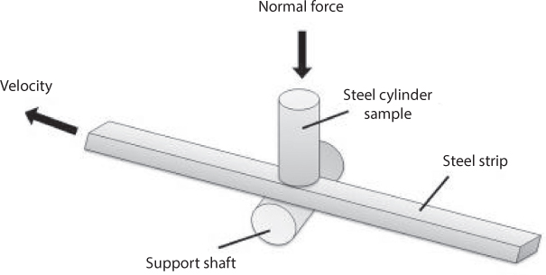
Figure 4.25 Schematic of the experimental setup. The strip is pulled at a constant velocity and pulling force is recorded.
The percentage reduction in the friction coefficient when using a textured sample, as compared to when using a non-textured sample, is shown in Figure 4.26 [69]. A larger reduction of friction coefficient was observed for the tests conducted with larger contact pressures of 60 and 120 MPa. Friction reduction also increased with faster sliding speeds. Note that the reduction in friction can be as high as 40%. Based on the previously presented results on the impact of friction reduction [70], friction and wear improvements resulting from this microtexturing should result in enhanced energy efficiency and an extended product life, thus saving both fuel and raw materials.

Figure 4.26 Percentage reduction in coefficient of friction from a non-textured to a textured surface.
4.2.1.2 Microtexturing Methods
This section describes methods for surface microtexturing, mainly two methods, laser machining and deformation based microtexturing.
Laser micro-machining
Laser micro-machining is a method of surface texturing that utilizes high-intensity picosecond or femtosecond laser pulses to incrementally ablate, or vaporize, minute segments of the substrate material to create the desired feature geometry. Coordination of laser pulses with workpiece movement allows the creation of virtually unlimited texture geometries; therefore, lasers are well suited to create rapid prototypes of surface texture designs.
The laser micro-machining system at Northwestern University consists of a diode pumped Nd:YVO4 picosecond Lumera Laser with 1064 nm and 532 nm wavelengths, as shown in Figure 4.27, with a pulse duration of approximately 8 ps. The laser has a variable repetition rate from 10 to 500 kHz. Average power at the 1064 nm wavelength is 2 W and peak power can reach 20 MW. Average output power is lower for the 532 nm wavelength. In general, as repetition rate increases, average power increases. The Aerotech positioning stage has five degrees of freedom (X, Y, Z, B, C) with linear accuracy of 10 nm and rotational accuracy of 10-4 degrees. The workpiece is mounted on the axes system and the part is moved incrementally in coordination with laser pulsing. The entire system is mounted on a large granite stage, which provides vibration isolation. The system was designed so that the laser beam would reach the sample in a vertical orientation. This allows the sensitive optics pieces to be rigidly mounted to the granite slab, with focusing of the objective occurring via movement of the z-axis. The part can be quickly moved through use of the x and y axes. The positioning stage movement is G-code programmable; position synchronized output allows external triggering of the laser beam in coordination with the stage movement. This allows laser micro-machining of complex shapes and patterns. CAD files of desired texture features can be converted to G-code for CNC machining. Post-processing can then converted to G-code commands accepted by the positioning system in order to control both the axes and laser pulsing. Generally, textures are created through the use of a rastering trajectory (Figure 4.28) with a low laser power and multiple passes used to reach the desired depth.

Figure 4.27 Laser micro-machining system, including a picosecond laser, a beam delivery system, and a 5 degree of freedom position stage.

Figure 4.28 Rastering trajectory for the creation of a rectangular surface texture feature. The green lines show the trajectory of the firing laser beam and the grey dashed lines show the trajectory followed while not firing.
Pulse repetition rate and movement speed are both factors in determining the pulse overlap, which is an important factor in determining the final microfeature geometry of a laser machined surface. Throughout this paper, pulse overlap in the X direction will be defined as the percentage of diameter overlap for successive pulses, while pulse overlap in the Y direction is the percentage of diameter overlap between subsequent channels. An illustration of diameter overlap is provided in Figure 4.29. The textures shown in subsections 4.3.1.1 were created using the laser setup described above and a geometrical prediction tool developed to estimate the ablated geometry based on input experimental baseline data and laser beam trajectory [56].
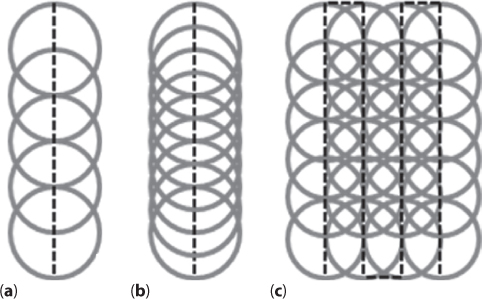
Figure 4.29 Illustration of pulse overlap. Grey circles represent the placement of laser pulses and black dashed lines follow the path of the laser beam. (a) and (b) represent 50% and 75% overlap in X, respectively, and (c) represents 50% overlap in X and 50% overlap in Y.
Microtexturing with direct laser ablation still has a materials limitation. For example, machining of transparent materials with picosecond lasers ha very low material removal rate and therefore low throughput. A newer process recently invented at Northwestern by Pallav and Ehmann [71], called Laser Induced Plasma MicroMachining (LIPMM), alleviates this issue. In LIPMM, the laser beam (Fig. 4.30a) is focused to a point inside a dielectric liquid using a converging convex spherical lens and the liquid undergoes deionization to create spot plasma at the focal spot (Figure 4.30b). If the workpiece is placed at the focal spot then this plasma almost instantaneously removes material from the workpiece, hence the designation Spot-LIPMM (S-LIPMM). The generated plasma is essentially deionized media at very high temperatures whose material removal abilities, when interacting with the workpiece, depend only on the energy intensity of the plasma and the thermal properties of the material. Another variant of this process is Line-LIPMM, in which the spot laser is expanded into a line and is used to create a line plasma, which is then used for machining (Figure 4.31). Features like channels are machined by translating the laser head as shown in Figure 4.28 and 4.29.
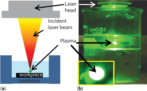
Figure 4.30 (a) Schematic of LIP-MP (b) Plasma in LIP-MP using distilled water and a ps.
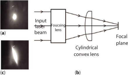
Figure 4.31 (a) CCD image of spot plasma (b) Optical arrangement for creating line plasma (c) CCD image of line plasma.
Figure 4.32 shows channels machined by S-LIPMM on semi-transparent polycarbonate and opaque ABS polymer sheets. Note that for all channel cross sectional profiles shown henceforth the measurements are made equidistant from each other along the channel length, from one end of the channel to the other. All measurements were performed using an ALICONA white light interferometer with a 50 nm resolution. Channels are also machined on completely transparent alumina ceramic and shiny silicon wafer (Figure 4.33), both brittle materials with different optical properties. The same materials were also machined using direct laser ablation with the same frequency, power and laser head movement. The transparent alumina ceramic could not be machined. For polycarbonate the heat-affected zone and tendency for carbonization of the surrounding areas were greater with laser ablation as compared to S-LIPMM (Figure 4.34). This shows that LIPMM can be used to machine a wider variety of materials than conventional direct laser ablation and can result in better feature quality for materials that have a tendency for high HAZ.

Figure 4.32 Channels machined on: (a) Polycarbonate (b) ABS (Power: 0.12 W, Frequency: 10 kHz, Dielectric: Distilled water, laser feed: 10 μm/s).
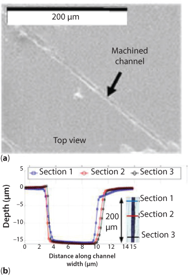
Figure 4.33 Channels machined on: a) Transparent alumina ceramic (b) Shiny silicon wafer (Power: 0.12 W, Frequency: 10 kHz, Dielectric: Distilled water, laser feed: 10 μm/s).

Figure 4.34 Channels machined on Polycarbonate with S-LIPMM and direct laser ablation (Power: 0.12 W, Frequency: 10 kHz, Dielectric: Distilled water, spot translated at 10 μm/s).
Channels machined with Line LIPMM on AA5052 workpiece material are shown in Figure 4.35. A significant advantage of L-LIPMM, over spot laser based ablation or S-LIPMM is its higher productivity as compared to S-LIPMM when machining micro-channels over large areas. The time required for machining an array of micro-channels (Figure 4.36) over an area of 6x6 mm with L-LIPMM, at a Z motion and in-plane motion speed of 10 μm/s is about 9 hours. The time taken for machining the same array of channels at the same laser head speeds with S-LIPMM, is 57 hours, which is about six times greater than with L-LIPMM. Moreover, since the essential physical principle of material removal in S-LIPMM and L-LIPMM is the same, it is expected that the multi-materials capability of S-LIPMM will be retained in L-LIPMM as well.
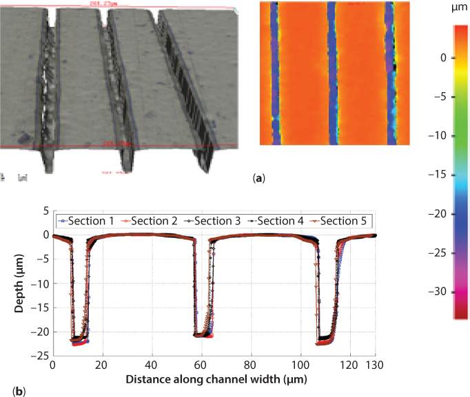
Figure 4.35 Channels machined on AA5052 with Line LIPMM (a) Optical view and depth plot of machined channels (b) cross sectional geometry of machined channels.

Figure 4.36 (a) Channel arrays on silicon machined using L-LIPMM (b) Alternating channel patterns on silicon using L-LIPMM.
Deformation based microtexturing
Deformation based methods are another way of microtexturing surfaces. One such method explored by our group is microrolling. The most significant advantage of microrolling is that the production rate of microtextures increases dramatically. This becomes especially important when textures have to be made over large surfaces, for example over large steel surfaces for increasing the energy yield from algae-based biofuels.
The essential idea behind microrolling is to scale down shaped rolling onto the micro scale so that microtexturing with a patterned roller is possible (Figure 4.37a). To realize this process our group developed and fabricated a Desktop μRolling Mill (DµRM), as shown in Figure 4.37b. This system uses one pair of rolls with only upper roll or both upper and lower rolls pretextured to plastically deform the top surface or both top and bottom surfaces of a thin sheet, creating an array of surface features through a combination of rolling and indentation actions. The rolls themselves can be made through micromachining, electro-discharge machining (EDM), or laser ablation. Another advantage of the proposed system is to provide a microforming method that can be implemented at room temperature without the need for heating of the tooling and the sheet material and is significantly faster and less expensive than etching or machining or laser texturing.

Figure 4.37 (a) Schematic of rollers with microchannel features (b) CAD model and fabricated DμRM (c) Schematic of DμRM.
The main frame of the DμRM, combining two pairs of flexure bearing housings (FBH), was cut from one piece of high strength steel block using wire EDM with accuracy as of 1 μm. As seen in Figure 4.37a, the upper roll is made with microchannel features. The gap between the upper and lower rolls is adjusted roughly by the wedge adjusting unit (Figure 4.37c) according to the required final depth of the surface features. Piezo-actuators are utilized to achieve the nanometer accuracy.
With continuous rolling process, the surface features of the roll are pressed against the contact surface of the sheet with a certain pressing force and are transferred to the sheet. The Flexible Bearing House (FBH) serves as the support mechanism as well as the guiding mechanism for the upper and lower rolls. Figure 4.38 shows the schematic of FBH, which is linked to the main frame with flexure hinges. FBH can provide precision vertical linear motion in a small range of 1 mm. Flexure hinges, with low rotational stiffness about one axis and high stiffness in other degrees of freedom, enable the FBH move vertically while keeping other degrees of freedom constrained. Furthermore, flexure hinges are clean room compatible and can be used in a vacuum environment. Compared with traditional bearing house, which assembles with linear bushing and sliding rod system, FBH has no assembly, and therefore, has no error accumulation, no backlash, no friction, and no need for lubrication.
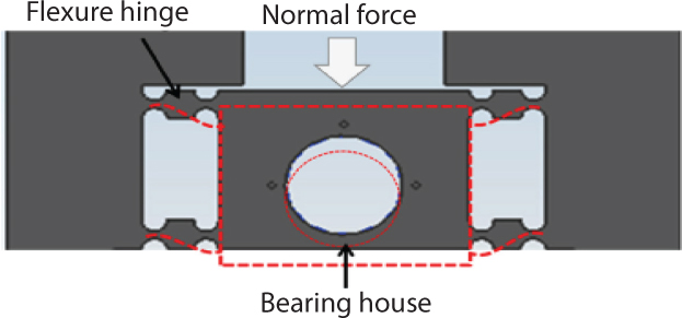
Figure 4.38 Schematic of Flexible Bearing House (FBH).
During surface texturing, the gap between the upper and lower rolls is first coarsely adjusted by the lower gap adjusting unit by pushing forward or pulling back the bottom wedge. Afterward, the upper adjusting unit with nanometer accuracy is used for fine adjustments and for the real-time adjustments during the surface texturing process. The upper adjusting unit is composed of a piezo actuator, a piezoelectric load cell, and a ball tip. Two piezo actuators with resolution of 0.8 nm press the left and right upper flexible bearing housings independently for closed-loop control of the gap between the upper and lower rolls and to prevent the tilting of the upper roll. Two piezoelectric load cells, installed between the piezo actuator and the ball tip, are used to monitor the rolling forces in real time. Ball tips, which are attached to the head of the piezo actuators, are used to prevent the application from both tilting and shearing forces, which can damage the piezo-actuators.
The gap between two rolls cannot be measured directly in the present setup. Instead, two noncontact capacitive position sensors are used to measure the gaps between the upper and lower flexure bearing houses at two ends of the rolls. In this way, the gap between two rolls can be calculated and any minor tilting of the roll can be detected very easily. Signal from the position sensor is fed into the control unit, so that the stroke of the piezo stack is carried out based on the signal to keep the gap between the upper and lower rolls at a required constant value.
The upper FBH is designed with high stiffness of 80 Ν/μm to ensure precise movements. In our system, since the lower FBH is supported by the wedge adjusting system, the requirement of stiffness can be compromised to achieve a larger stroke for coarse adjustment. The critical stress is calculated based on the stroke length and is designed to be far below the yield stress of the material to ensure the safety of the whole system. The natural frequencies of both FBHs are designed to be much higher than the frequency of the texturing process in order to avoid system resonances. Two electric motors rotate the two rolls independently, giving them the same or different rotational speeds up to 20 rpm according to applications. The roll with surface features is made of tungsten carbide for the high stiffness and strength. The two piezo actuators are capable of providing up to 60 kN force and 150 μm stroke length with 0.8 nm resolution. The stiffness of the piezo actuator is 360 Ν/μm and the resonant frequency is 4.5 kHz. The piezoelectric load cell has a high rigidity of 5 kN/μm and can measure up to 30 kN load. The capacitive position sensor, with a measurement range up to 2 mm and a resolution as small as 10 nm, is selected for noncontact position measurement.
In addition, in a collaborative project with researchers at University of Connecticut and Deringer Ney Inc., pressure sensors were also used for online pressure measurement during the microrolling process [72]. The sensor consists of three major components: 1) an array of electrodes embedded under the roll surface to form capacitors along the axial direction of the roll, where capacitance values formed by the electrodes are proportional to the deformation of the roll surface, 2) a custom designed high precision capacitance measuring circuit that is free of the effect of stray capacitance, and 3) a pressure retrieval algorithm to reconstruct the pressure distribution across the roll from the measured capacitance data.
Figure 4.39a illustrates the configuration of the embedded sensor, which consists of a ceramic sensing rod and a series of electrodes attached to its surface. Another electrode, called excitation electrode, is attached to the inner surface of the sensor mounting hole drilled along the axial direction of the roll. The excitation and receiving electrodes are separated by a layer of plastic film coated on the receiving electrodes. As a result, when the sensing rod is inserted into the mounting hole, a series of capacitors C1, C2, … CN are formed along the roll surface. The embedded sensor was designed and fabricated, as shown in Figure 4.39b, for real-time monitoring of the pressure distribution in a microrolling mill. A total of four receiving electrodes were realized on a 9.5 mm diameter fiber plastic sensing rod. The sensing rod was incorporated into a 65 mm diameter roll made of D2 tool steel, at a depth of 2 mm underneath the surface.

Figure 4.39 (a) Schematic of capacitive pressure sensor (b) Fabricated pressure sensor.
The textured roll (Figure 4.40a) itself consisted of three sections, each having a width of 10 mm and separated from the next section by a 3 mm wide flat area. The width and height of the teeth in the three sections are around 50 μm x 110 μm, 15 μm x 30 μm, and 50 μm x 60 μm, respectively. To reconstruct the pressure distribution from the measured capacitance, a quantitative relationship between the pressure and the capacitance was established [72]. Figure 4.40b shows the recorded roll pressure.

Figure 4.40 (a) Microroller used for texturing in [73] (b) Measurement of roll pressure as a function of set gap between rolls (c) Measurement of channel depth as a function of location along the roller axis.
When the gap between the rolls decreases, the pressure on the workpiece increases as it is fed into the smaller gap. This is reflected in the increased measured capacitance and roll pressure. To verify the result, the depth of the imprinted channels on the rolled workpiece was measured by a NewView 7000 Series white light interferometer (WLI). For each section on the workpiece, the channel depth was measured at three positions near which the sensor passed through the roll-workpiece contact zone, in order to calculate the average channel depth, as shown in Figure 4.40c. Considering the dimension of the teeth is different in each section, these average channel depth was normalized by the teeth height (channel depth divided by the teeth height). Since the roll gap of all the experiments was set to fully indent the teeth into the workpieces, the channel width and depth were different based on the pressure exerted: a higher forming pressure results in a deeper channel, and vice versa. As a result, the formed channel depth will be closer to the actual dimension of the teeth on the roll when forming force increases. Such a trend is seen in Figure 4.40: at each gap size, the channel depth in the middle section is higher than that in either the left or the right section. The largest channel depth in the middle section confirms the reconstructed pressure distribution from the sensor data, where the highest pressure is found to be in the same section.
The DμRM setup described above was also used for texturing regular and irregular grid patterns on the surface of sheets, by manipulating the position of the sheet after every pass of the sheet through the rolls [73]. An example of this method is shown in Figure 4.41a and some channels and grid patterns fabricated using this method are shown in Figure 4.41b. Multipass deformation based microrolling can also be used to increase the depth of the rolled channels. For example, Figure 4.42a shows channels and their cross sectional profiles formed after one pass, and Figure 4.42b shows an increase in the channel depth after two passes. The measured cross sectional profiles of formed two-pass channels with different set roll gaps are shown in Figure 4.42c. Note that as the set roll gap increases and the number of passes increases, the deformed channel depth increases as well.

Figure 4.41 (a) Multipass forming strategy for forming non-regular channels (b) Channels and textures formed using the DμRM setup and multipass forming strategy.
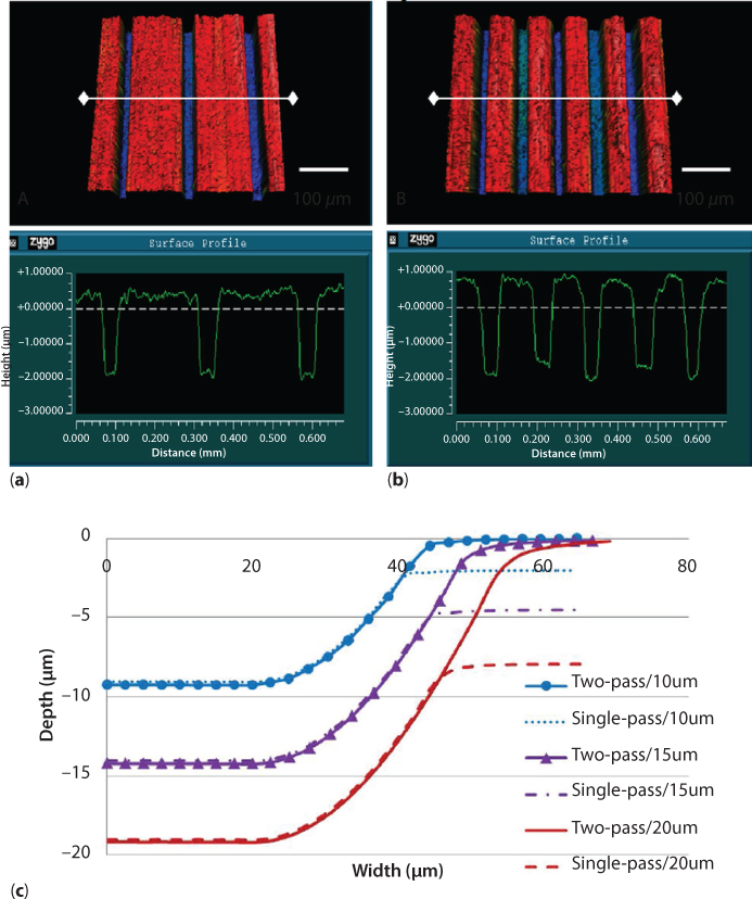
Figure 4.42 Deformed channel geometry (a) after one roll pass (b) after two roll passes (c) as a function of roll pass and set roll gap.
These results show that microrolling can be used to create microtextured surfaces, with a significant advantage that the throughput is orders of magnitude greater than in laser based texturing.
4.2.1.3 Future Work in Microtexturing
This section has illustrated the applications of surface texturing in creating energy savings, as well as laser texturing and deformation based methods which were used for creating microtextured surfaces.
Laser-based texturing methods provide a highly accurate and controllable way of creating these microtextures. Further research needs to be done for investigating the ablation mechanics of laser ablation and correlating the created microtexture to the laser process parameters. At the same time laser machining is suitable only for low volume production or small area texturing and suffers from the issue of a limited multi-materials capability. On the other hand, deformation based microtexturing methods like microrolling provide a high throughput means for microtexturing. Further research in this area must be performed on investigating the deformation behavior of the sheet and relate it to the process parameters so that a priori estimation of the process parameters is possible and the possibility of forming channels with higher aspect ratios can be realized.
Deformation based methods still have materials limitation. For example, brittle materials like ceramic would be hard to texture with microrolling. Newer processes like Laser Induced Plasma MicroMachining [74–75] have shown a significantly expanded multi-materials capability. Further research in this process as well the creation of newer processes with an even more expanded multi-materials capability is very much warranted.
Another much needed area of potential research is an examination of the correlation between the texture type and the function of the microtextured surface. For example, recent work has shown that friction reduction due to surface texturing is highly dependent on the dimple geometry and the application. Computational models of the type developed by Wang and Zhu [76], in which surfaces were virtually textured and the lubricated contact behavior was determined, will go a long way in the widespread use of microtexturing for friction reduction. In the same spirit, models for predicting the enhancement or retardation of algae and microbial growth on textured surfaces can help accelerate current applications in the energy harvesting sector as well as new applications in self-cleaning and microbe-resistant surfaces in the biomedical sector.
4.3 Summary
This chapter presented two examples in energy manufacturing, an innovative flexible dieless forming process for reducing energy utilization in low-volume sheet metal production and a microtextured surface that can reduce energy consumption in utilization. Fundamental features and future research directions have been discussed for each example.
4.4 Acknowledgement
The authors would like to acknowledge the financial support provided by the following agencies
- Incremental Forming: National Science Foundation USA, Department of Energy USA
- Laser microtexturing: National Science Foundation USA
- Laser Induced Plasma Micromachining: National Science Foundation USA
- Microrolling: National Science Foundation USA
We would also like to acknowledge our collaborators on:
- Incremental Forming: Prof. John Roth, Prof. Tim Gutowski, Dr. Cedric Xia, Dr. Vijitha Kirdena, Dr. Feng Ren, Prof. Ted Belytchsko, Prof. John Ziegert, Prof. Scott Smith
- Laser microtexturing: Prof. Kornel Ehmann, Prof. Jane Wang, D. Cedric Xia, R. Talwar and R. Lederich
- Laser Induced Plasma Micromachining: Prof. Kornel Ehmann
- Microrolling: Prof. R.X. Gao and E.F. Smith III
as well as the students and postdocs who worked on these projects including:
- Incremental Forming: Dr. Ying Huang and Michael Beltran
- Laser microtexturing: Dr. Tiffany Davis Ling, Kumar Pallav and Pinzhi Liu
- Laser Induced Plasma Micromachining: Kumar Pallav and Ishan Saxena
- Microrolling: Z. Fan, Man-Kwan Ng
References
1. Jeswiet, J., Incremental single point forming. Transactions of NAMRI/SME, 29, p. 75–79, 2001.
2. Jeswiet, J., et al., Asymmetric Single Point Incremental Forming of Sheet Metal. CIRP Annals - Manufacturing Technology, 54(2), p. 88–114, 2005.
3. Emmens, W.C., G. Sebastiani, and A.H. van den Boogaard, The technology of Incremental Sheet Forming—A brief review of the history. Journal of Materials Processing Technology, 210(8), p. 981–997, 2010.
4. Meier, H., C. Magnus, and V. Smukala, Impact of superimposed pressure on dieless incremental sheet metal forming with two moving tools. CIRP Annals - Manufacturing Technology, 60(1), p. 327–330, 2011.
5. Meier, H., et al., Increasing the part accuracy in dieless robot-based incremental sheet metal forming. CIRP Annals - Manufacturing Technology, 58(1), p. 233–238, 2009.
6. Malhotra, R., et al., Improvement of Geometric Accuracy in Incremental Forming by Using a Squeezing Toolpath Strategy With Two Forming Tools. Journal of Manufacturing Science and Engineering, 133(6), p. 061019: 1–10, 2011.
7. Malhotra, R., et al., Accumulative-DSIF strategy for enhancing process capabilities in incremental forming. CIRP Annals - Manufacturing Technology, 61(1), p. 251–254, 2012.
8. Leszak, E., Apparatus and Process for Incremental Dieless Forming, 1967.
9. Dittrich, M.A., Gutowski, T.G., Cao. J, Roth, J.T., Xia, Z.C., Kiridena, V., Ren, F., Henning, F. “Exergy Analysis of Incremental Sheet Forming”, Production Engineering Research & Development, Vol. 6, pp. 69–177, 2012.
10. Kalpakjian S.R., Manufacturing Engineering and Technology, 2008.
11. Walczyk, D.F., J. Lakshmikanthan, and D. Kirk, A Reconfigurable Tool for Forming Aircraft Body Panels. SME Journal of Manufacturing Systems. 17(4), p. 287–296.
12. Cai, Z.-Y., M.-Z. Li, and Y.-W. Lan, Three-dimensional sheet metal continuous forming process based on flexible roll bending: Principle and experiments. Journal of Materials Processing Technology, 212(1), p. 120–127, 2012.
13. Allwood, J.M. and H. Utsunomiya, A survey of flexible forming processes in Japan. International Journal of Machine Tools and Manufacture, 46(15), p. 1939–1960, 2006.
14. Schmoeckel, D., et al., Metal Forming of Tubes and Sheets with Liquid and Other Flexible Media. CIRP Annals - Manufacturing Technology, 48(2), p. 497–513, 1999.
15. Daehn, G.S., High Velocity Metal Forming, in ASM handbook, ASM international. p. 405–418, 2006.
16. Dittrich, M.A., et al., Exergy analysis of incremental sheet forming. Production Engineering, 6(2), p. 169–177, 2012.
17. Szargut, J., D.R. Morris, and F.R. Steward, Exergy Analysis of Thermal, Chemical and Metallurgical Processes, 1988 Hemisphere Publishing Corporation.
18. Huang, Y., et al., Prediction of Forming Limit in Single Point Incremental Forming With the Ductile Fracture Criterion. ASME Conference Proceedings, 2007(42908), p. 929–934, 2007.
19. Malhotra, R., Xue, L., Cao, J., Belytschko, T., Smith, Scott K. and Ziegert, J., Prediction and Analysis of Fracture in Single Point Incremental Forming using a Damage based Material Model, NAMRC, Vol. 39, Proceedings of NAMRI/SME, 2011.
20. Kalpakjian, S. and S.R. Schmid, Manufacturing processes for engineering materials. 5th ed., 2008.
21. Smil, V., Energies – An Illustrated Guide to the Biosphere and Civilization MIT Press, 1999.
22. Lee, S.M., Handbook of Composite Reinforcements: Wiley-VCH, 1992.
23. Xia, Z.C., et al., Rapid Freeform Sheet Metal Forming: Technology Development and System Verification, 2013, Department of Energy.
24. Allwood, J.M., D. Braun, and O. Music, The effect of partially cut-out blanks on geometric accuracy in incremental sheet forming. Journal of Materials Processing Technology, 210 p. 1501–1510, 2010.
25. Allwood, J.M., et al., Closed-loop feedback control of product properties in flexible metal forming processes with mobile tools. Annals of the CIRP, 58(1), p. 287–290, 2009.
26. Tekkaya, A.E., et al., Surface reconstruction for incremental forming. Production Engineering, 1, p. 71–78, 2007.
27. Malhotra, R., Fundamentals of Process Mechanics and Process Innovation in Incremental Forming, in Mechanical Engineering, Northwestern University, 2012.
28. Lingam, R., et al., Compensations for toolpath to enhance accuracy during Double Sided Incremental Forming, in ASME 2015 International Manufacturing Science and Engineering Conference, p. 8, North Carolina, USA.
29. H., R., N. Moser, and J. Cao, Simulation and Analysis of Double-Sided Incremental Forming Considering Machine Compliance, in NUMIFORM: The 12th international conference on industrial forming processes 2016: Troyes, France. p. 3.
30. Zeng, Q., K.F. Ehmann, and J. Cao, Tri-pyramid Robot: Design and kinematic analysis of a 3-DOF translational parallel manipulator. Robotics and Computer-Integrated Manufacturing, 30(6), p. 648–657, 2014.
31. Ren, H., et al., Effects of Tool Positions in Accumulated Double-Sided Incremental Forming on Part Geometry. Journal of Manufacturing Science and Engineering, 137(5), p. 051008, 2015.
32. Ndip-Agbor, E., et al., Optimization of relative tool position in accumulative double sided incremental forming using finite element analysis and model bias correction. International Journal of Material Forming, 9(3), p. 371–382, 2016.
33. Zhang, Z., et al., A Mixed Double-Sided Incremental Forming Toolpath Strategy for Improved Geometric Accuracy. Journal of Manufacturing Science and Engineering, 137(5), p. 051007–051007, 2015.
34. Hussain, G., et al., The effect of variation in the curvature of part on the formability in incremental forming: An experimental investigation. International Journal of Machine Tools & Manufacture, 47, p. 2177–2181, 2007.
35. Filice, G., F. Ambrogio, and Micari, On-Line Control of Single Point Incremental Forming Operations through Punch Force Monitoring CIRP Annals - Manufacturing Technology, 55(1), p. 245–248, 2006.
36. Szekeres, A., M. Ham, and J. Jeswiet, Force Measurement in Pyramid Shaped Parts with a Spindle Mounted Force Sensor. Key Engineering Materials, 344, p. 551–558, 2007.
37. Emmens, W.C., D.H. vanderWeijde, and v. A.H. The FLC, Enahnced Formability, and incremental sheet forming in Proceedings of the International Deep Drawing Research Group IDDRG 2009 International Conference 2009 Golden, CO, USA.
38. Jackson., K. and J. Allwood, The mechanics of incremental sheet forming. Journal of Materials Processing Technology, 209(3), p. 1158–1174, 2009.
39. Allwood, J.M., D.R. Shouler, and A.E. Tekkaya, The increased forming limits of incremental sheet forming processes. Key Engineering Materials, 344, p. 621–628, 2007.
40. Emmens, W.C. and A.H. vandenBoogard, An overview of stabilizing deformation mechanisms in incremental sheet forming. Journal of Material Processing Technology, 209, p. 3688–3695, 2009.
41. Yao, H. and J. Cao, Prediction of forming limit curves using an anisotropic yield function with prestrain induced backstress. International Journal of Plasticity, 18(8), p. 1013–1038, 2002.
42. Smith, L.M., et al., Influence of Transverse Normal Stress on Sheet Metal Formability. Journal of Plasticity, 19(1567–1583), 2003.
43. Madeira, T., et al., Failure in single point incremental forming. The International Journal of Advanced Manufacturing Technology, 80(9), p. 1471–1479, 2015.
44. Cerro, I., et al., Theoretical and experimental analysis of the dieless incremental sheet forming process. Journal of Materials Processing Technology, 177(1–3), p. 404–408, 2006.
45. Van Bael, A., et al., Forming limit predictions for single point incremental sheet metal forming. Proceedings of the 10th ESAFORM Conference on Material Forming, AIP Conference Proceedings (907), p. 309–314, 2007.
46. Huang, Y., et al., Experimental and Numerical Investigation of Forming Limits in Incremental Forming of a Conical Cup. Transaction of the North American Manufacturing Research Institution of SME., 2008.
47. Malhotra, R., et al., Mechanics of fracture in single point incremental forming. Journal of Materials Processing Technology, 212(7), p. 1573–1590, 2012.
48. Xue, L., Damage accumulation and fracture initiation in uncracked ductile solids subjected to triaxial loading. International Journal Solids and Structures, 44(16), p. 5163–5181, 2007.
49. Xue, L. and T. Belytschko, Fast methods for determining instabilities of elastic-plastic damage models through closed-form expressions. International Journal for Numerical Methods in Engineering, 84(1490–1518), 2010.
50. Smith, J., et al., Deformation mechanics in single-point and accumulative double-sided incremental forming. The International Journal of Advanced Manufacturing Technology, 69(5), p. 1185–1201, 2013.
51. Lu, B., et al., Investigation of material deformation mechanism in double side incremental sheet forming. International Journal of Machine Tools and Manufacture, 93, p. 37–48, 2015.
52. Xu, D.K., et al., Enhancement of process capabilities in electrically-assisted double sided incremental forming. Materials & Design, 92, p. 268–280, 2016.
53. Valoppi, B., et al., A hybrid mixed double-sided incremental forming method for forming Ti6Al4V alloy. CIRP Annals - Manufacturing Technology, 65(1), p. 309–312, 2016.
54. H. Meier and C. Magnus, Incremental Sheet Metal Forming with Direct Resistance Heating Using Two Moving Tools Key Engineering Materials, 554–557: p. 1362–1367, 2013.
55. Franzen, V., et al., Single point incremental forming of PVC. Mater. Process. Technol., 209 (1) p. 462–469, 2009.
56. Franzen, V., et al., On the capability of single point incremental forming for manufacturing PVC sheet parts. ICTP-2008, International Conference on Technology of Plasticity, Gyeongju, Korea, 2008.
57. Davarpanah, M.A., et al., Effects of incremental depth and tool rotation on failure modes and microstructural properties in Single Point Incremental Forming of polymers. Journal of Materials Processing Technology, 2015. 222: p. 287-230.
58. Council, U.S.N.R., Elements of Polymer Fire Safety and Guide to the Designer: Report, National Academies. p. 151, 1979.
59. Digges, K.H., et al., Human survivability in motor vehicle fires. Fire and Materials, 32(4), p. 249–258, 2008.
60. Bagudanch, I., et al., Forming force and temperature effects on single point incremental forming of polyvinylchloride. Journal of Materials Processing Technology, 219, p. 221–229, 2015.
61. Yonan, S.A., et al., Plastic flow and failure in single point incremental forming of PVC sheets. Express Polymer Letters, 8(5), p. 301, 2014.
62. Davarpanah, M.A., S. Bansal, and R. Malhotra, Influence of Single Point Incremental Forming on Mechanical Properties and Microstructural Morphology of Polymers. ASME Journal of Manufacturing Science and Engineering, 2016, 9 pages.
63. Davarpanah, M.A., et al., Preliminary investigations on Double Sided Incremental Forming of thermoplastics. Manufacturing Letters, 8, p. 21–26, 2016.
64. Silva, M.B., L.M. Alves, and P.A.F. Martins, Single point incremental forming of PVC: Experimental findings and theoretical interpretation. European Journal of Mechanics - A/Solids, 29(4), p. 557–566, 2010.
65. Yonan, S.A., et al., A simple finite strain non-linear visco-plastic model for thermoplastics and its application to the simulation of incremental cold forming of polyvinylchloride (PVC). International Journal of Mechanical Sciences, 66, p. 192–201, 2013.
66. Magnus, C., B. Buff, and H. Meier, Flexible Production of Small Lot Sizes by Incremental Sheet Metal Forming with Two Moving Tools, in New Production Technologies in Aerospace Industry: Proceedings of the 4th Machining Innovations Conference, Hannover, September 2013, B. Denkena, Editor, Springer International Publishing: Cham. p. 33–37, 2014.
67. B. Lu, et al., Cranial Reconstruction Using Double Side Incremental Forming Key Engineering Materials, 639, p. 535–542, 2015.
68. Xu, R., et al., A preliminary study on the fatigue behavior of sheet metal parts formed with accumulative-double-sided incremental forming. Manufacturing Letters, 2(1), p. 8–11, 2014.
69. Davis, T., et al., Experimental Friction Study of Micro-Scale Laser-Textured Surfaces, in International Workshop on Microfactories 2008: Evanston, IL.
70. Holmberg, K., P. Andersson, and A. Erdemir, Global energy consumption due to friction in passenger cars. Tribology International, 47(0), p. 221–234, 2012.
71. Pallav, K. and K. Ehmann, Feasibility of Laser Induced Plasma Micro-machining (LIP-MM). Precision Assembly Technologies and Systems IFIP Advances in Information and Communication Technology, 315 p. 73–80, 2010.
72. Fan, Z., et al., Real-time monitoring of pressure distribution in microrolling through embedded capacitive sensing. CIRP Annals - Manufacturing Technology, 61(1), p. 367–370, 2012.
73. Zhou, R., et al., An investigation on deformation-based micro surface texturing, ASME Journal of Manufacturing Science and Engineering, 133(6), 2011.
74. Malhotra, R., et al., Laser-induced plasma micro-machining (LIPMM) for enhanced productivity and flexibility in laser-based micro-machining processes. Accepted to the Annals of CIRP, 1, 2013.
75. Pallav, K. and K.F. Ehmann, Feasibility of laser induced plasma micro-machining (LIP-MM). IFIP Advances in Information and Communication Technology, 315, p. 73–80, 2010.
76. Wang, Q.J. and D. Zhu, Virtual texturing: Modeling the performance of lubricated contacts of engineered surfaces. Journal of Tribology-Transactions of the ASME, 127(4), p. 722–728, 2005.