
Chapter 7
Surface Treatment and Tribological Considerations
1University of Notre Dame, IN, USA
2Queens University, Kingston, Ontario, Canada
*Corresponding author: [email protected]
Abstract
This chapter begins with a classification and description of the major surface treatment and coating processes (heat treatment and surface hardening, coating, texturing, and surface stress-inducing operations). Heat treatment and surface hardening operations include furnace methods as well as those using laser or electron beams to locally affect the microstructure. A wide variety of coating operations are available, but the chapter emphasizes those processes that lead to performance improvement (not merely aesthetic changes) such as thermal spraying, hard facing, physical and chemical vapor deposition, as well as certain electroplating operations. Texturing includes high-energy beams (laser, electron beam and electrical discharge approaches) as well as texturing through surface replication or machining. Stress-inducing operations include peening, burnishing, and explosive hardening. Current practices are summarized along with typical applications of each approach, and process models for energy needs are summarized. Energy requirements are presented for each process class, and areas for efficiency improvement identified. The importance of tribology and its position in a full life-cycle analysis is outlined. The chapter closes with an investigation of emerging areas in surface engineering.
Keywords: Tribology, coatings, surface engineering, hardening
7.1 Introduction
Since the Industrial Revolution the number of parts in products has increased as our ability to fabricate more complicated and smaller parts faster has increased. Figure 7.1 shows this trend and there is every reason to believe that with micro- and nanomanufacturing this trend will increase. An example of how an idea can generate a product that can become increasingly more sophisticated and complex is the mobile (cell) phone. In Dick Tracy comics (1950s) a wrist watch cell phone was used. Later (1970s) bulky hand held phones were available. These became increasingly smaller with the result that today we have very compact, hand held cell phones with many more microfabricated parts and very large markets for them. Surfaces will be part of this increase.

Figure 7.1 Increasing product complexity since the industrial revolution.
The technological shifts that have occurred in surface technology in the past ten years are inherently linked to the changes in advanced manufacturing, and in many cases micromanufacturing and nanotechnology Alting et al., [1].
It is often imperative to modify the surface properties of a product in order to improve performance. This can be done for a number of reasons, including:
- Wear resistance is often necessary, requiring a harder surface or deposition of a coating
- Improved fatigue performance, as can be obtained by inducing a compressive residual stress
- Corrosion prevention, such as with galvanic coatings
- Prevention of adhesion and reduction of friction, perhaps by promoting lubrication
All of these processes add to the energy required to produce a product. Product lifecycle analysis would need to capture the performance and life improvements that result in order to evaluate the true cost of these processes. For example, a shot peening operation may have a cost in terms of time and energy, but it may be necessary to make a product perform as required, or else it improves performance or life. If the benefits of added performance and life are not included in the lifecycle analysis, then it is difficult to justify surface treatments.
Ancillary equipment plays a large part in the energy consumption associated with surface treatment processes. Hermann et al., [2] surveyed the capabilities and limitations of modern manufacturing systems simulation with respect to energy flows. They evaluated the effects of batch processing, reduction in the numbers of machines in production, automatic shutdown of idling machines, etc., and estimated energy savings. It has been noted that each machine that actually performs a manufacturing task requires the operation of ancillary equipment such as blowers, fans, pumps, lights, etc., so that the accounting of energy may not be straightforward. Gutowski et al., [3] have calculated the ancillary equipment requirements for some cases, suggesting that the energy consumed in a part is
(7.1)
where ECp represents the energy needs of the machinery used in manufacturing and ECa is the energy needs of ancillary equipment. ECp is the energy requirement that is mainly addressed in this chapter, but Gutowski, et al., [3] suggest that ECp may be as small as 12% of the total energy consumed to produce a part, E. ECa is quite difficult to predict with accuracy, as some machinery has continuously operating components while others will shut down during periods of inactivity. The specific energy requirements for different classes of machines to process one kilogram of material is shown in Figure 7.2. From this, the following can be observed:
- The energy requirements are strongly related to the process rate for slow processes. This is attributable to the higher energy input required for machining or polishing at ever lower length scales, as well as energy consumption when a machine is ‘ready’ but not yet actively processing material. An example of the latter case is when an electroplating tank is brought to temperature and agitated, but is waiting for product to be introduced into the tank.
- Each manufacturing process can have a range of performance. For example, in shot peening, the specific energy and process rate can vary greatly depending on the surface finish that is being produced, and the media used.
- The historical trend is towards increased application of more energy-intensive operations and products.
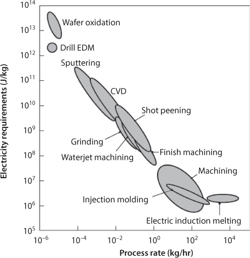
Figure 7.2 Specific energy requirements for various manufacturing processes including ancillary equipment. Source: After Gutowski et al., [2011], with additional processes included.
It should also be noted that this chapter provides only a broad overview of the different surface treating processes, with a special emphasis on energy requirements. More detailed publications, and in most cases, handbooks, have been written on each of these approaches, to which the interested reader can refer for more detailed information. Further, this chapter does not describe methods used to evaluate coatings, such as wear or corrosion resistance, hardness, etc.
7.2 Surface Treatment Techniques
The surface properties of products are often modified in order to improve performance. Reasons for modifying surfaces include:
- Wear resistance
- Improved fatigue performance
- Corrosion prevention
- Reduction of friction
Surfaces have been considered differently with time. Figure 7.3 shows how emphasis has changed Jiang et al., [4]. In early days (1920s) surface texture was regarded as incidental. The emphasis was to make the surface as smooth as possible. Over time texture also was utilized as a functional attribute with size and shape still being major requirements. Surface geometry is now regarded as fundamental both in the control of manufacture and functional performance and as such has to be taken into account by the design and production. Recently it was suggested that a modified classification system be used that it based on identifying the critical surface attributes/topographic features and relating these to their function. Figure 7.4 indicates how this would work.

Figure 7.3 Development of the role of surface geometry Jiang et al., [4].

Figure 7.4 Surface classification hierarchy proposed Jiang et al., [4].
The major surface treatment operation classes are outlined in Figure 7.5. As with coating operations, there are many specialized forms of these and related processes, and this figure only addresses the most common approaches.

Figure 7.5 Outline of major surface treatment processes.
7.2.1 Surface Geometry Modification
Traditional machining and abrasive finishing operations are discussed in this chapter, and are essential for obtaining required tolerances and surface finish for many applications. Examples are the machining, shaving, or grinding of gear teeth to obtain desired quality levels. For the most part, these processes are intended to produce smooth surfaces, and any texture that results is generally secondary to the roughness goals.
Recently, significant attention has been directed toward the use of texturing approaches to reduce friction and wear. As an example of this approach, it is known that, with very smooth surfaces in contact, adhesive forces can become very large. This can be problematic in many applications, but notably with hard drives used for information storage. To prevent hard drive heads from damaging surfaces during startup, the heads are moved to a location on the disk that is not used for storage. However, the strong adhesion can result in wear particles that could be disastrous for performance, or it can result in a head sticking to the surface. A solution is to use laser texturing to locally roughen the hard drive surface, with the intent of making the head/disk contact less intimate (Figure 7.6).

Figure 7.6 Application of laser texturing to a surface. (a) Crater with rims, as is used to reduce adhesion in computer hard drives; (b) Crater with rim removed, as is used to provide enhanced lubricant transport.
Another application of such texturing is for entrainment of lubricant. With smooth surfaces, it can be very difficult to entrain a lubricant film under normal conditions or startup. Patir and Cheng demonstrated that lubricant can be transported by even Gaussian surfaces, but orientation is important. Some processes have a pronounced orientation, such as grinding and polishing operation, but others result in isotropic surfaces, such as shot peening or anodizing.
Recently, research has been directed towards applying texturing approaches that lead to non-Gaussian distributions. Typical approaches used involve using a laser or electron beam to locally melt material and form a crater whose rim may be subsequently removed, depending on the particular requirements. A pattern of such craters without rims have been shown to help entrain lubricants in metal working and other applications.
7.2.2 Microstructural Modification
Many surface treatments involve improving the performance of a material by changing the microstructure near the surface. These can involve cold work or heat treatment.
Shot Peening and Roller Burnishing
Compressive residual stresses can be imparted through shot or laser peening and roller burnishing and may be obtained in forging, extrusion, or rolling. Shot peening (Figure 7.7) is a cold working process in which the surface of a part is impacted with small spherical media called shot. Each impact leads to plastic deformation at the workpiece surface, leading to compressive residual stress after elastic recovery. The layer under compressive residual stress is usually less than 1 mm thick, and the material bulk properties are unaffected. Crack development and propagation are severely retarded by compressive residual stresses; for this reason, shot peening is a common surface treatment for fatigue-susceptible parts such as gears, springs, shafts (especially at stress concentrations), connecting rods, etc.

Figure 7.7 Schematic illustration of shot peening. (a) Illustration of a surface subjected to multiple impacts by spherical shot, with a detailed view emphasizing the thickness affected; (b) typical beneficial effects of shot peening on fatigue properties of metals. Source: (b) courtesy of J. Champaigne, Electronics Inc.
The beneficial effect of shot peening on fatigue life can be seen in Figure 7.7b. Similar behavior can be found for other materials. This is an important tool for fatigue design because it represents one of the only strategies that increases the fatigue strength of materials, and this increase can be very large. For example, consider an aircraft landing gear, produced from steel with a 2068 MPa (300 ksi) strength. Shot peening can increase the fatigue strength by a factor of 3 over a polished surface [5], and by a factor of 10 for welds. Similar benefits are possible with other materials, but as seen in the figure, the more typical fatigue strength improvement is 15% to 30%.
If an irregularly shaped abrasive particle or cut wire is used as the media instead of the shot, abrasion can result on the surface layer of the work-piece. This can remove oxide layers or prepare a surface for further operations such as coating or painting.
A surface layer can also be cold worked by the action of a hard and highly polished roller or set of rollers, referred to as roller burnishing. The process is used on various flat, cylindrical, or conical surfaces. As opposed to shot peening, roller burnishing improves surface finish by removing scratches, tool marks, and pits, and induces beneficial compressive surface residual stresses.
Energy use in shot peening varies greatly according to the material, shot type and size, and intensity. In theory, the kinetic energy of the particles can be transferred to the workpiece and results in plastic deformation, but in practice, workpiece restitution limits the amount of energy that can be transferred, and this depends on material and part geometry.
Induction Hardening
Induction hardening is a heat-treating process that does not alter the chemistry of surface layers. This process involves the heating of an electrically conductive workpiece by inducing a current from a magnetic field generated by an external coil. The coil can be shaped to a particular workpiece to increase efficiency, as shown in Figure 7.8.

Figure 7.8 Typical induction hardening arrangements. Source: Courtesy of Kalpakjian and Schmid [2014].
Induction hardening is widely used for carbon steels, where the work-piece is raised to temperatures for which the stable phase is austenite; rapid quenching leads to martensite formation. Induction heating and flame hardening are used for gear and sprocket teeth, axles, crankshafts, piston rods, etc. These processes usually develop a maximum case depth of around 0.25 in, and result in surface hardnesses of 50–60 HRC.
The process energy required is dependent on the part geometry and the accuracy of the coil form, but the minimum energy required is that needed to raise the workpiece to the austenite range (minimum of 738 °C).
Cold Working
Cold working is a deformation process discussed in Chapter 5, but it is also useful as a surface hardening process. Recognizing that plastic deformation is usually localized at the tool interface, cold worked materials can have a higher hardness at the surface than in the substrate.
The energy required to obtain a part through cold working is determined, to a great extent, by its design attributes and manufacturing strategy. In theory, this is fairly straightforward to obtain, as the energy needs in, for example, machining can be obtained theoretically using cutting mechanics or experimentally by measuring energy consumption of a machine tool. This can be compared to predictions of other manufacturing strategies. For example, consider the simple case of a 304 stainless steel, 14 mm diameter, 150 mm long rod that is to be reduced in diameter to 12 mm by machining or by pulling it in tension.
For the case where deformation occurs through tension, Kalpakjian and Schmid [2008] suggest that this material can be modeled by a power law constitutive model given by
(7.2)
where the strain in this case is
(7.3)

Therefore, the specific energy needed is
(7.4)

so that the work needed is
(7.5)

For the machining case, Kalpakjian and Schmid [2008] give the specific energies needed to machine selected materials. From this, the average value of 4.1 W-s/mm3 is selected for 304 stainless steel. The volume removed is
(7.6)

so that the work required for machining is
(7.7)
Note that the energy required for machining is over six times the energy required for achieving the desired geometry by simple stretching. This energy estimate is actually quite low; usually such machining will be done in a number of passes, with higher specific energy associated with the finishing cut.
Of course, the rod in this example is from a standard sized specimen, and the energy costs associated with reducing its diameter could be avoided if the rod had been manufactured to the desired size in the first place. This is not always the best strategy, especially given surface finish and tolerance requirements that may require machining operations.
7.2.3 Chemical Approaches
Basically, these are operations where the component is heated in an atmosphere containing elements (such as carbon, nitrogen, or boron) that alter the composition, microstructure, and properties of surfaces. For steels with sufficiently high carbon content, surface hardening takes place without using any of these additional elements; only the heat-treatment processes described in Section 7.2.2 are needed to alter the microstructures, usually by either flame hardening or induction hardening. The chemical approaches to hardening are summarized in Table 7.1.
Table 7.1 Summary of heat treating processes involving chemical diffusion into surfaces.
| Process | Metals hardened | Element added to surface | Procedure | General characteristics | Typical applications |
| Carburizing | Low-carbon steel (0.2% C), alloy steels (0.08-0.2% C) | C | Heat steel at 870°-950°C in an atmosphere of carbonaceous gases (gas carburizing) or carbon-containing solids (pack carburizing). Then quench. | A hard, high-carbon surface is produced. Hardness 55 to 65 HRC. Case depth up to 1.5 mm. Some distortion of part during heat treatment. | Gears, cams, shafts, bearings, piston pins, sprockets, clutch plates |
| Carbonitriding | Low-carbon steel | C and N | Heat steel at 700°-800°C in an atmosphere of carbonaceous gas and ammonia. Then quench in oil. | Surface hardness 55 to 62 HRC. Case depth 0.07 to 0.5 mm. Less distortion than in carburizing. | Bolts, nuts, gears |
| Cyaniding | Low-carbon steel (0.2% C), alloy steels (0.08-0.2% C) | C and N | Heat steel at 760°-845°C in a molten bath of solutions of cyanide (e.g., 30% sodium cyanide) and other salts. | Surface hardness up to 65 HRC. Case depth 0.025 to 0.25 mm. Some distortion. | Bolts, nuts, screws, small gears |
| Nitriding | Steels (1% Al, 1.5% Cr, 0.3% Mo), alloy steels (Cr, Mo), stainless steels, high-speed tool steels | N | Heat steel at 500°-600°C in an atmosphere of ammonia gas or mixtures of molten cyanide salts. No further treatment. | Surface hardness up to 1100 HV. Case depth 0.1 to 0.6 mm and 0.02 to 0.07 mm for high speed steel. | Gears, shafts, sprockets, valves, cutters, boring bars, fuel-injection pump parts |
| Boronizing | Steels | B | Part is heated using boron-containing gas or solid in contact with part. | Extremely hard and wear resistant surface. Case depth 0.025 to 0.075 mm (0.001 to 0.003 in.). | Tool and die steels |
7.3 Coating Operations
The major types of coating operations are outlined in Figure 7.9. It should be noted that there are specialized forms of each process, and these are the major classes.

Figure 7.9 Outline of the major coating processes.
7.3.1 Hard Facing
Hard facing refers to deposition of a hard, often metallic, coating onto a workpiece.
Thermal Spray
Thermal spraying is a series of processes in which coatings of various metals, alloys, carbides, ceramics, and polymers are applied to metal surfaces by a spray gun, with a stream heated by an oxyfuel flame, an electric arc, or a plasma arc. The earliest applications of thermal spraying, in the 1910s, involved metals; hence, the term metallizing has also been used. The coating material can be in the form of wire, rod, or powder, and when the droplets or particles impact the workpiece, they solidify and bond to the surface.
Particle velocities typically range from a low of about 150 up to 1000 m/s, but can be higher for special applications. Temperatures are in the range of 3000° to 8000 °C. The sprayed coating is hard and wear-resistant, with a layered structure of deposited material. However, the coating can have a porosity as high as 20% due to entrapped air and oxide particles.
Typical applications of thermal spraying include aircraft engine components (such as those used in rebuilding worn parts), structures, storage tanks, tank cars, rocket motor nozzles, and components that require resistance to wear and corrosion. In an automobile, thermal spraying is often applied to crankshafts, valves, fuel-injection nozzles, piston rings, and engine blocks. The process is also used in the gas and petrochemical industries, for the repair of worn parts, and to restore dimensional accuracy to parts that may have not been machined or formed properly.
The energy source used in thermal-spraying processes is of two types: combustion and electrical, summarized as follows:
- Combustion Spraying
- Thermal wire spraying (Figure 7.10a): The oxyfuel flame melts the wire and deposits it on the surface. The bond is of medium strength, and the process is relatively inexpensive.
- Thermal metal-powder spraying (Figure 7.10b): This process is similar to thermal wire spraying, but uses a metal powder instead of the wire. The higher area-to-volume ratio of the powder facilitates heating.
- Detonation gun: Controlled and repeated explosions take place by means of an oxyfuel–gas mixture. The detonation gun has a performance similar to that of plasma.
- High-velocity oxyfuel-gas spraying (HVOF): This process has characteristics similar to those of the detonation gun, but is less expensive.
- Electrical Spraying
- Twin-wire arc: An arc is formed between two consumable wire electrodes. The resulting bond has good strength, and the process is relatively inexpensive.
- Plasma: Either conventional, high-energy, or vacuum (Fig. 6.10c) plasma produces temperatures on the order of 8300°C and results in good bond strength with very low oxide content.

Figure 7.10 Schematic illustrations of thermal-spray operations: (a) thermal wire spray, (b) thermal metal-powder spray, and (c) plasma spray. Source: From Kalpakjian and Schmid [2014].
7.3.2 Vapor Deposition
Chemical Vapor Deposition
Chemical vapor deposition (CVD) is a thermochemical process (Figure 7.11). CVD is a very versatile process – almost any material can be coated and any material can serve as a substrate, although bond strength will vary. Details about the CVD process, including chemistries involved in industrially significant coatings, are available in Bhushan and Gupta [6].
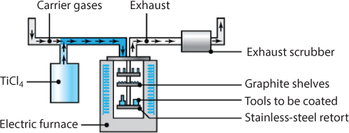
Figure 7.11 Schematic illustration of the chemical-vapor-deposition process. Note that parts and tools to be coated are placed on trays inside the chamber. Source: From Kalpakjian and Schmid [2014].
In a typical application, such as coating cutting tools with titanium nitride, the tools are placed on a graphite tray and heated to 950° to 1050°C, at atmospheric pressure and in an inert atmosphere. Titanium tetrachloride (a gas), hydrogen, and nitrogen are then introduced into the chamber. The chemical reactions form titanium nitride on the tool surfaces, with hydrogen chloride produced and exhausted from the reaction chamber. Because of its toxicity, however, this exhaust gas must be carefully cleaned using exhaust scrubbers before being vented to the atmosphere. For a coating of titanium carbide, methane is substituted for the other gases.
Deposited CVD coatings usually are thicker than those obtained with PVD. A typical cycle is long, consisting of (a) three hours of heating, (b) four hours of coating, and (c) six to eight hours of cooling to room temperature. The thickness of the coating depends on the flow rates of the gases used, time, and temperature.
Physical Vapor Deposition
The three basic types of physical vapor deposition (PVD) processes are (a) vacuum deposition or arc evaporation; (b) sputtering; and (c) ion plating. These processes are carried out in a high vacuum and at temperatures in the range from 200° to 500°C. In PVD, the particles to be deposited are carried physically to the workpiece, rather than through chemical reactions, as in chemical vapor deposition.
In vacuum deposition or evaporation, the metal is evaporated at a high temperature in a vacuum and is deposited on the substrate, which usually is near room temperature. Coatings of uniform thickness can be deposited, even on complex shapes. In arc deposition (PV/ARC), the coating material (cathode) is evaporated by several arc evaporators (Figure 7.12), using highly localized electric arcs. The arcs produce a highly reactive plasma, which consists of the ionized vapor of the coating material; the vapor condenses on the substrate (anode) and coats it. Applications of this process are both functional (oxidation-resistant coatings for high-temperature applications, electronics, and optics) and decorative (hardware, appliances, and jewelry).

Figure 7.12 Schematic illustration of the arc deposition process. Note that there are three arc evaporators and the parts to be coated are placed on a tray inside the chamber. Source: From Kalpakjian and Schmid [2014].
In sputtering, an electric field ionizes an inert gas (usually argon); the positive ions then bombard the coating material (cathode) and cause sputtering (ejection) of its atoms. The atoms condense on the workpiece, which is heated to improve bonding (Figure 7.13). In reactive sputtering, the inert gas is replaced by a reactive gas (such as oxygen), in which case the atoms are oxidized and the oxides are deposited. Carbides and nitrides also are deposited by reactive sputtering. Alternatively, very thin polymer coatings can be deposited on metal and polymeric substrates with a reactive gas, causing polymerization of the plasma.
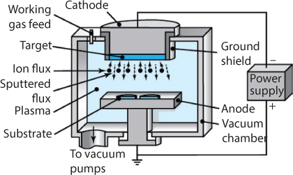
Figure 7.13 Schematic illustration of the sputtering process. Source: From Kalpakjian and Schmid [2014].
Ion plating is a generic term that describes various combined processes of sputtering and vacuum evaporation. An electric field causes a glow, generating a plasma; the vaporized atoms are ionized only partially. Ion-beam-enhanced (assisted) deposition is capable of producing thin films as coatings for semiconductor, tribological, and optical applications. Bulky parts can be coated in large chambers using high-current power supplies of 15 kW and voltages of 100,000 DC.
7.3.3 Miscellaneous Coating Operations
Hot Dipping
In hot dipping or dip coating, the workpiece (usually steel or iron) is dipped into a bath of molten metal, such as (a) zinc, for galvanized-steel sheet and plumbing supplies; (b) tin, for tinplate and tin cans for food containers; (c) aluminum (aluminizing); and (d) terne, an alloy of lead with 10% to 20% tin. Hot-dipped coatings on discrete parts provide long-term corrosion resistance to galvanized pipes, plumbing supplies, and many other products.
Automotive steel sheet metal is almost always galvanized (zinc-coated) by hot dipping. In this process, the steel sheet is annealed in a continuous furnace with controlled atmosphere and temperature, and dipped in molten zinc at about 450 °C. The thickness of the zinc coating is controlled by a wiping action from a stream of air or steam, called an air knife. Proper draining for the removal of excess coating materials is important for product quality.
Electroplating
In electroplating, the workpiece (cathode) is plated with a different metal (anode), which is transferred through a water-based electrolytic solution. Although the plating process involves a number of reactions, the process consists basically of the following sequence:
- The metal ions from the anode are discharged by means of the potential energy from the external source of electricity or are delivered in the form of metal salts.
- The metal ions are dissolved into the solution.
- The metal ions are deposited on the cathode.
The volume of the plated metal can be calculated from the equation
(7.8)
where I is the current in amperes, t is time, and c is a constant that depends on the plate metal, the electrolyte, and the efficiency of the system; typically, it is in the range of 0.03-0.1 mm3/amp-s. Note that for the same volume of material deposited, the deposited thickness is inversely proportional to the surface area. The deposition rate is typically on the order of 75 μm/h; thus, electroplating is a slow process. Thin-plated layers are typically on the order of 1 μm; for thick layers, the plating can be as much as 500 μm.
The plating solutions are either strong acids or cyanide solutions. As the metal is plated from the solution, it has to be periodically replenished. This is accomplished through two principal methods: (a) salts of metals are occasionally added to the solution or (b) a sacrificial anode of the metal to be plated is used in the electroplating tank and dissolves at the same rate that the metal is deposited.
Simple electroplating can be done in a single-process bath or tank, but more commonly, a sequence of operations is involved in a plating line. The following equipment and processes may be part of an electroplating operation:
- Chemical cleaning and degreasing tanks will be used to remove surface contaminants and enhance surface adhesion of the plated coating.
- The workpieces may be exposed to a strong acid bath (pickling solution) to eliminate or reduce the thickness of the oxide coating on the workpiece.
- A base coating may be applied. This may involve the same or a different metal than that of the ultimate surface; for example, if the desired metal coating will not adhere well to the substrate, an intermediate coating can be applied. Also, if thick films are required, a plating tank can be used to quickly develop a film; and a subsequent tank, with brightener additives in the electrolytic solution, is used to develop the final surface finish.
- A separate tank performs final electroplating.
- Rinse tanks will be used throughout the sequence.
Rinse tanks are essential for several reasons. Some plating is performed with cyanide salts delivering the required metal ions. If any residue acid (such as that from a pickling tank) is conveyed to the cyanide-solution tank, poisonous hydrogen-cyanide gas is exhausted. This is a significant safety concern; thus, environmental controls are essential in plating facilities. Also, plating solution residue will contain some metal ions, and it is often desirable to recover those ions by capturing them in a rinse tank.
Common plating metals are chromium, nickel (for corrosion protection), cadmium, copper (corrosion resistance and electrical conductivity), and tin and zinc (corrosion protection, especially for sheet steel). Chromium plating is done by first plating the metal with copper, then with nickel, and finally with chromium. Hard chromium plating is done directly on the base metal and results in a surface hardness of up to 70 HRC and a thickness of about 0.05 mm or higher. This method is used to improve the resistance to wear and corrosion of tools, valve stems, hydraulic shafts, and diesel- and aircraft engine cylinder liners.
Examples of electroplating include copper-plating aluminum wire and phenolic boards for printed circuits, chrome-plating hardware, tin-plating copper electrical terminals (for ease of soldering), galvanizing sheet metal, and plating components such as metalworking dies that require resistance to wear and galling (cold welding of small pieces from the workpiece surface). Metals such as gold, silver, and platinum are important electroplating materials in the electronics and jewelry industries for electrical contact and for decorative purposes, respectively.
Plastics, such as ABS, polypropylene, polysulfone, polycarbonate, polyester, and nylon, also can be electroplated. Because they are not electrically conductive, plastics must first be preplated by a process such as electroless nickel plating. This process is carried out by a chemical reaction and without using an external source of electricity. The most common application utilizes nickel as the plating material, although copper also is used. In electroless nickel plating, nickel chloride (a metallic salt) is reduced to nickel metal (with sodium hypophosphite as the reducing agent), which is then deposited on the workpiece. The hardness of nickel plating ranges between 425 and 575 HV; the plating can subsequently be heat treated to 1000 HV. The coating has excellent wear and corrosion resistance.
Conversion Coatings
Because of the demanding environment encountered in metal forming, conversion coatings of phosphate crystals are often used. An outstanding summary of conversion coating behavior is given by Bay [7]. Conversion coatings do not lubricate themselves, but they serve as excellent carriers of other lubricants, usually soaps or solid lubricants such as molybdenum disulphide or graphite. For light duty applications, emulsions or oils may impregnate the conversion coating. SEM images of conversion coatings are shown in Figure 7.14. A typical conversion coating consists of platelets of phosphates that grow in the same direction as surface grains. The platelets are 10 μm to 100 μm in size and produce a porous coating 1 μm to 10 μm in thickness. The pores in the phosphate can serve as liquid lubricant reservoirs, but more normally, this coating serves as a carrier for solid lubricant layers deposited over it.

Figure 7.14 SEM images of phosphate coatings, from Bay [7]. (a) Needle structure; (b) grainy structure.
Conversion coatings were first developed in metal forming for cold steel forging, although chemistry modifications allow application of phosphate coatings to aluminum, zinc, titanium, and stainless steel forging and extrusion. After phosphating, the lubricant layers are physically applied, resulting in a layered surface such as that shown in Figure 7.15. Special care must be taken in developing soap layers of proper thickness; insufficient film thickness results in rapid tool wear while excess soap can build up on tooling and compromise part tolerances.
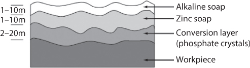
Figure 7.15 Schematic illustration of phosphate coating with soap coatings.
Metal coatings are often used in combination with a liquid lubricant. For example, tin and zinc can be applied to sheet metal to reduce die pickup and improve formability. The liquid lubricant used is then formulated for the coating, not the base material, so the coating can be considered as the lubricant carrier. Copper is sometimes used, since die pickup is minimal and copper has a low shear stress.
7.4 Tribology
Consider again the sample case of Section 6.6.2.2, wherein a 14 mm diameter 304 stainless steel rod is reduced to a 12 mm diameter rod, but in this case by drawing through a 10° die with a coefficient of friction of 0.2. This is a very high value of friction coefficient, and actually would not allow reasonable reductions in area through drawing, but can be illustrative to show the contribution of friction to the energy needed by a process. Saha [8] gives the drawing pressure as

For this case, the draw stress is then found to be 233.7 MPa, leading to a prediction of required work of 3964 J. Note that this represents an 8% increase compared to the uniaxial stretching (ideal work) case. While the results can vary somewhat depending on the particular geometry and reductions used, the example is valuable for noting that if lubricants or tooling could be found that eliminated friction, a persuasive argument for lubricant use would not come from the direct energy savings. Further, much of the ancillary equipment discussed in Section 3.2 is associated with lubricant application, filtration, refinement, recovery and disposal.
To the tribology practitioner, this is of course a misleading approach. Effective lubricants are needed not because they reduce energy or force requirements (although they accomplish this feat), but because they make operations possible. That is, without good lubrication in stretch forming, strains will localize and sheet metal will fracture prematurely. Poor lubrication in drawing or rolling leads to galling and loss of surface finish. Excessively thin lubricant films in hot forging lead to fast cooling and strengthening of the workpiece, and associated dramatic rises in forging loads, modifications to the strain distribution, and associated cracking.
From a lifecycle standpoint, the circumstance without lubrication would need to account for lost energy associated with defective or fractured parts. There is an energy cost associated with lubricant production, and lubricants contribute to the carbon footprint in a complete lifecycle analysis. For this reason, more environmentally sound lubricants have been investigated [12], but energy-related arguments are not made for their adoption, and often performance suffers when they are adopted. Thus, a green lubricant may not actually be green if the full environmental effects are considered.
Equation (7.9) is useful because it incorporates both specific process and ancillary equipment energy consumption, but it cannot be useful as a means of evaluating lubricants or even justifying any efforts in tribology at all. This is not a surprise; even the Jost Report’s [9] famous prediction that 10% of gross domestic product could be saved through application of tribology principles included the cost of premature failure of products, it was not based solely on energy savings. Applied to manufacturing, Eq. (7.9) would need to be modified, such as by
(7.10)
where γ is the rate at which scrap is produced in manufacturing operations. This can be significant; one of the drawbacks to operations such as manually controlled spinning and explosive forming is the very high scrap rates, which can approach 50% in some cases. Referring to Fig. 3, the processes that produce the highest quality surfaces and have the largest associated costs also have fairly large defect rates, mainly because of the demanding design specifications in the microelectronics and relevant MEMS applications.
Not all defects are associated with tribological principles, so the factor γ could be aggregated into a number of subfactors. For example, integrated circuits admittedly have many defects associated with die-to-pad bonding (although this may be associated with solid mechanics or poor control of ultrasonic welding). However, it should be recognized that modern industrial practice in a competitive marketplace is incompatible with the energy consumption and associated costs associated with a large vale of γ.
7.5 Evolving Technologies
7.5.1 Biomimetics – Biologically Inspired Design
Engineers are now looking at biology for ideas for new designs; hence, we will briefly consider biologically inspired design. The design and manufacture of new surfaces are affected by this.
In their evolution, animals and plants (the biological world) have evolved many elegant solutions to engineering problems; hence, biologists, designers, and engineers are working together using solutions from the natural world to solve present-day product surface engineering problems [17].
As an aside, looking at the biological world for inspiration is not a new idea. Linnæus [10] set up a categorization method for plants. According to Du Rietz [11], recorded instances of looking at nature can be traced back to Theophrastos in 300 BC.
Definitions for Biomimetics
In studying the intersection of the biological and engineering world it useful to define commonly related terms as did Shu [12]. These include: bioengineering, biological engineering, biotechnical engineering, biomechanics, biomedical engineering, biophysics, bionics, and biomimetics. According to Shu, biomimesis, biomimicry, biognosis, bioinspiration, biomimetic design, bioanalogous design, and biologically inspired design are synonymous with biomimetics and mean emulating natural models, systems, and processes to solve human problems.
According to Shu [12], biomimetic manufacturing can be organized according into three groupings:
- Cutting, electrophysical and chemical processes, forming, and grinding/abrasive processes
- Machines, surfaces, and precision engineering
- Life-cycle engineering and assembly, design, production systems and organizations
The first two include surface phenomena. Three of the many examples given by Shu [12] include: 1) the self-sharpening, by wearing away a tungsten carbide-cobalt ‘dentine-like’ backing material, to continually sharpen the hard titanium nitride ‘enamel-like’ cutting edge of teeth in rodents; 2) porous ZnO films that have properties such as near-UV emissions, optical transparency, electrical conductivity and piezoelectricity, that make the films well suited to microelectronic devices, e.g., solar cells: 3) the replication of sharkskin to give low friction properties that facilitate swimming speeds of up to 60 km/hr.
On the same subject of biologically-inspired surface design and manufacture, Malshe [13] writes that active interfaces between surfaces and the environment are becoming more efficient by using combinations of available materials, along with unique physical and chemical strategies, which include features such as texturing and structure; and chemical strategies such as sensing and actuation. These collectively enable functional surfaces to deliver extraordinary adhesion, hydrophobicity, multispectral response, energy scavenging, thermal regulation, antibiofouling, and other advanced functions. Production industries now implement these architectures into manufactured consumer products. Other examples include: 1) the hulls of boats imitating the thick skin of dolphins [14]; and nanostructures and physical mechanisms that produce the shining color of butterfly wings [15].
Leaf surface has an effect upon the efficiency of plant photosynthesis Nobel et al., [16]. Illumination level has been shown to have a large influence during leaf development. Cell surface area per unit leaf area and the photosynthetic rate are directly related. The relative importance of accounting for changes in photosynthesis was quantitatively evaluated using equations based on analogies to electrical circuits.
In this process, the surface of the plant leaves and some bacteria use solar energy along with carbon dioxide (CO2) and water from the atmosphere to generate oxygen and carbohydrates.
(7.11)
This reaction provides a inspiration for solar cells, which convert solar energy directly into electricity.
7.6 Micro Manufacturing
The motivation for increasingly smaller components is due to the demand for reduced weight, reduced dimensions, higher surface quality, and part accuracy Dornfeld et al., [17]. Examples of products are components of devices ranging from electro-mechanical instruments to medical devices. With the ability now to do microforming and micromachining (micromanufacturing), associated surface technologies are an area of interest worldwide. Examples of what has been found are Dornfeld et al., [17]:
- Cutting forces at the ultra precision scale are expected to be low (~0.1 N and lower) with low power requirements. With depths of cut at 5 nm to 57 nm, surface roughness will be in the same range.
- Crystallographic orientation affects surface roughness and cutting force for single crystal copper and aluminum in ultra-precision diamond cutting.
- A microsurface effect is that cutting force varies as the tool passes grain boundaries.
- At the micro level, material properties become non-homogeneous and thus, variation in material hardness causes cutting tool vibration. This effect is significant at low feed and cutting speed and leads to irregular surface roughness.
- Micro-pattern generation can be done on either flat or curved surfaces that are used as reflectors, abrasives, and other functions. Traffic signs, Fresnel lenses, and possible CMP (chemical mechanical planarization) pad surfaces are typical examples.
- Surface Effects on grinding of ultra-fine, cylindrically shaped microtools having a tip diameter of less than 1 µm have been produced successfully.
- It was found that differences in surface characteristics exert an extremely strong influence on mechanical strength of the tool. In addition, the results suggest that the surface of processed microtools might be strengthened by allowing the penetration and diffusion of oxygen atoms into the material, and allowing oxidation giving a protective surface.
De Chiffre et al., [18] showed surface applications that include, computer chips, data storage, MEMS, biomedical systems, micro-optical systems, X-ray optics, fuel cells, and implants, where functions can be optical, fluid dynamic, tribological, biomedical, mechanical, chemical, or aesthetic.
- The magnetic properties of a computer hard disk are influenced by a surface region several nanometers thick. In order to minimize head stiction to the disk surface, surface polishing is followed by a texturing process producing circumferential grooves or laser texturing, the overall roughness of the structured surface being Rq = 3-5 nm De Chiffre et al., [18].
Surface mechanisms are of tremendous importance in determining the reliability MEMS.
7.7 Conclusions
A wide variety of surface treatment and coating operations exist, with the main goals of improving wear or fatigue performance, corrosion resistance, or aesthetics. Some treatments are used to assist in reducing friction or improving lubrication. All of the processes described have a large specific energy content, so that they are in general a large contributor to the energy content in products. However, the surface treatments and coatings are often necessary to achieve required performance, or else they greatly extend a product’s life. Hence, even though a product may have a larger energy content as a result of a surface treatment or coating, the complete lifecycle of a product is favorably affected.
References
1. Alting, L., Kimura, F., Hansen, H.N., Bissacco, G., Micro Engineering, CIRP Annals, v. 52/2, pp. 635–657, 2003.
2. Hermann, C., Thiede, S., Kara, S., and Hesselbach, J., “Energy oriented simulation of manufacturing systems – concept and application”, CIRP Annals – Manufacturing Technology, v. 60, pp. 45–48, 2011.
3. Gutowski, T., Dahmus, J., and Thiriez, A., “Electrical Energy Requirements for a Manufacturing Process,” Proceedings of the 13th CIRP International Conference on Life Cycle Engineering, Leuven, May, 2006.
4. Jiang, XJ, Whitehouse, DJ, “Technological shifts in surface metrology”, CIRP Annals - Manufacturing Technology, v. 61, pp. 815–836, 2012.
5. Schmid, S.R., Hamrock, B.J., and Jacobson, B.O., Fundamentals of Machine Elements, 3rd ed., CRC Press, 2014.
6. Bhushan, B., and Gupta, B.K., Handbook of Tribology. McGraw-Hill, 1991.
7. Bay, N., “Cold Forging Lubricants,” Proc. 1st Int. Conf. On Tribology in Manufacturing Processes, Gifu, Japan, pp. 9–21, 1997.
8. Saha, P., Aluminum Extrusion Technology, ASM International, 2000.
9. Lubrication (Tribology) Education and Research (the Jost Report), Department of Education and Science, HMSO, London, 1966.
10. Linnæus, C., Systema naturæ, sive regna tria naturæ systematice proposita per classes, ordines, genera, & species. pp. 1–12, Johann Wilhelm de Groot for Theodor Haak, 1735.
11. Du Rietz, E G. 1931. “Life Forms of Terrestrial Flowering Plants”, ACTA Phytogeographica, Uppsala 1931.
12. Shu, L., Ueda K., Chiu I., Cheong H. “Biologically inspired design”. CIRP Annals - Manufacturing Technology (2011).
13. Malshe, A, et al., “Bio-inspired functional surfaces for advanced applications”. CIRP Annals - Manufacturing Technology, 2013.
14. Vincent, J. 2009 http://www.bath.ac.uk/news/2009/04/28/is-technology-darwinian/; accessed June 2012.
15. Parker, G. http://www.nano.ecs.soton.ac.uk/news; accessed June 2012.
16. Nobel P.S., Zaragoza L.J., Smith W.K. “Relation between Mesophyll Surface Area, Photosynthetic Rate, and Illumination Level during Development for Leaves of Plectranthus parviflorus Henckel”. Plant Physiology, June 1975, vol. 55, no. 6, pp. 1067–1070.
17. Dornfeld, D., Min, S., and Takeuchi, Y., “Recent Advances in Mechanical
Micro Machining”. Annals of the CIRP, vol. 55/2, 2006.
18. De Chiffre L, Kunzmann H, G. Peggs GN, Lucca DA. “Surfaces in Precision Engineering, Microengineering and Nanotechnology”. Annals of the CIRP, vol. 52/1, 2003.