
Chapter 6
Nontraditional Removal Processes
Murali Sundaram1* and K.P. Rajurkar2
1Micro and Nano Manufacturing Laboratory, Mechanical and Materials Engineering, University of Cincinnati, Ohio, USA
2Center for Nontraditional Manufacturing Research (CNMR), Mechanical and Materials Engineering, University of Nebraska-Lincoln, USA
*Corresponding author: [email protected]
Abstract
Electrical discharge and electrochemical processes belong to a group of nontraditional manufacturing processes that primarily use electricity or the effect of electricity to produce desired features by material removal. The electrical energy requirements for these processes are of significant importance as electrical energy is controlling the material removal in these processes. The processes included in this chapter are electrical discharge machining (EDM), electrochemical machining (ECM), and electrochemical hybrid techniques, namely, electrochemical discharge machining (ECDM), and electrochemical grinding (ECG). This chapter discusses these processes with the perspective of their energy efficiency.
Keywords: Electro-discharge machining (EDM), electrochemical machining (ECM), electrochemical discharge machining (ECDM), electrochemical grinding (ECG)
6.1 Introduction
Electrical discharge and electrochemical processes belong to a group of nontraditional manufacturing processes that primarily use electricity or the effect of electricity to produce desired features by material removal [1]. The electrical energy requirements for these processes are of significant importance as electrical energy is controlling the material removal in these processes. The processes included in this chapter are electrical discharge machining (EDM), electrochemical machining (ECM), and electrochemical hybrid techniques, namely, electrochemical discharge machining (ECDM), and electrochemical grinding (ECG). This chapter discusses these processes with the perspective of their energy efficiency.
6.1.2 Working Principle
6.1.2.1 Electrical Discharge Machining
Electrical Discharge Machining (EDM) is a non-contact, unconventional, thermal machining process capable of machining conductive and semi-conductive materials regardless of their hardness. Conversion of electrical energy to thermal energy through repeated occurrence of sparks between the tool and the workpiece immersed in a dielectric medium, as shown in Figure 6.1 and separated by a small distance (spark gap), results in the material removal from both workpiece as well as tool by melting, evaporation, and by spalling in some special cases.

Figure 6.1 Schematic of Electro-Discharge Machining Process (right picture: Kunieda, M., Kruth, J. P., Rajurkar, K. P., Schumacher, M., Advancing EDM through Fundamental Insight into the Process. CIRP Annals - Manufacturing Technology, 2005. 54(2): p. 64–87).
Though the EDM process is highly complex and stochastic in nature, there exists a common understanding of the sequence of events in EDM and corresponding material removal mechanism as shown in Figures 6.2 and 6.3 respectively.
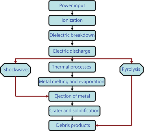
Figure 6.2 Sequence of events in EDM process.
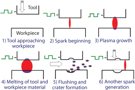
Figure 6.3 Illustration of the EDM process mechanism.
The material removed is the major source of debris particles produced, which are removed by the recirculation of dielectric. The common dielectric fluids used are kerosene, paraffin, and light hydrocarbon oils. A necessary condition for producing a discharge is the ionization of the dielectric medium and splitting up its molecules into ions and electrons (i.e., formation of plasma). Die-sinking EDM and Wire EDM (WEDM) are the two dominant EDM process variants.
6.1.2.2 Electrochemical Machining
Electrochemical machining (ECM) is a non-contact process by which material is removed by the mechanism of targeted anodic dissolution during an electrolysis process. The anodic dissolution rate, which is governed by Faraday’s laws of electrolysis, depends on the electrochemical properties of the metal, electrolyte properties, and the type of electric current/voltage supplied. The cathode or the tool remains unaffected during the ECM process. This gives ECM an advantage over many other processes, as there is no tool wear or other issues such as distortion due to residual stress that may warrant tool change. The schematic for ECM is given in Figure 6.4 with an illustration of the electrolysis of iron in a sodium chloride solution. The prominent chemical reactions that take place in the electrolytic cell are described below [2].

Figure 6.4 Schematic of electrochemical machining process.
The anodic reactions are mainly the dissolution of iron into the metal ion. The breakdown of water results in oxygen being liberated [2].

The cathodic reactions are primarily the generation of hydrogen gas and hydroxyl ions [2].

The overall reaction products are the formation of ferrous hydroxide due to the reaction of the metal ions with hydroxyl ions. Further reaction with water produces ferric hydroxide [2].
Thus, this overall electrolysis process shows the dissolution of iron from the anode and the generation of hydrogen at the cathode with some reactant products, such as ferrous hydroxide, precipitated out.
Pulse electrochemical machining (PECM) is a variation where a pulsed power is used instead of DC current. PECM improves ECM performance especially in the microscale fabrication, and leads to higher machining accuracy, better process stability and suitability for control. These advantages are due to the improved electrolyte flow condition in the interelectrode gap, enhanced localization of anodic dissolution, and small and stable gaps found in PECM. The PECM process has been used in the fabrication of microholes, microslots, and high aspect ratio tools. Pulsed current has also found applications in the electrochemical co-deposition (plating) of microtools.
6.1.2.3 Electrochemical Discharge Machining
Electrochemical discharge machining (ECDM) is a hybrid machining process that is a combination of electro-discharge machining (EDM) and electrochemical machining (ECM). The schematic for ECDM is given in Figure 6.5. The primary advantage of this machining technique is its ability to machine nonconductors. An example of chemical reactions that may occur during the ECDM machining of glass is described below [3].
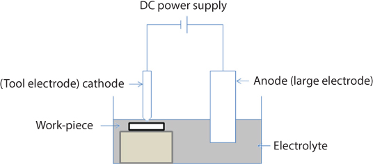
Figure 6.5 Schematic of electrochemical discharge machining process.
1. Ion Exchange:
The release of alkali metals from network terminal sites, which is modeled to occur through ion exchange with protons from water producing silanol groups and free alkali.
≡ Si –O –Na + H2O → ≡ Si –OH(Silanol) + M+ – OH−
2. Network Hydrolysis:
Hydrolysis reactions are thought to be responsible for the degradation and dissolution of the silicate network.
≡ Si –O –Si ≡ + OH– → ≡ Si –O– + HO – Si ≡
3. Network Dissolution:
Hydrolysis of terminal - Si groups leads to dissolution of glass, forming aq. silicic acid as follows:
≡ Si –O –Si(OH)3 + H2O → ≡ Si –OH + H4 SiO4 (aq)
Due to the combined action of EDM and ECM, high material removal rates are achieved in this process. High aspect ratio structures with minimum surface cracks and good surface finish can be achieved with ECDM. Industrial application of ECDM is somewhat limited due to the lack of reproducible machining in the order of few microns.
The power supply used for ECDM can be either a constant DC voltage or a pulsed power supply. To avoid anodic polarization of the tool, it is used as a negative electrode. The positive electrode has a large surface area (100 times that of the tool electrode) as compared to the negative electrode, and is kept at a large distance from the cathode. The positive electrode should have good corrosion resistance from the electrolyte being used. The depth of the tool electrode in the electrolyte is kept to a few millimeters. Electrochemical discharges happen when the applied voltage exceeds the critical voltage, which in turn depends on the geometry of the tool and the concentration of the electrolyte.
The material removal rate increases with the concentration of the electrolyte to a certain extent and then decreases. It also increases with the electrolyte temperature and the applied DC voltage. Tool wear rate also increases with the machining rate. Rotation of the tool electrode improves the surface quality. The feed mechanisms used for the tool electrode are gravity feed, constant feed, and stick-slip actuators. In deep-hole drilling, the electrolyte movement to the machining site can be improved by moving the tool up and down during machining. The transition from traditional electrolysis to electrochemical discharges is explained using many theories like change in the wettability of the electrode, hydrodynamic instabilities, local joule heating, a combination of wettability and hydrodynamic effects, and bubble coalescence as a percolation problem.
6.1.2.4 Electrochemical Grinding
Electrochemical grinding (ECG) removes material from workpiece (anode) by combination of abrasive action and electrochemical dissolution. An electrically conductive abrasive wheel serves as a cathode, which connects with the workpiece and a low-voltage DC power supply in an electric circuit. About 10% material removal is attributed to abrasive action, while the remainder occurs by anodic dissolution. The electrolyte is flushed over the abrasive wheel during this process. The debris generated by electrochemical dissolution is removed by the abrasive grit, thereby exposing a fresh surface for further electrochemical attack. The difference between ECG and ECM processes lies in the form of the tool used. The ECM tool is a mirrored replica of the feature desired to be machined on the workpiece, while the ECG tool is an abrasive tool, usually in the form of a grinding wheel.

Figure 6.6 Schematic of electrochemical grinding process.
Electrochemical grinding neither causes thermal damage nor induces residual stresses in the machined work surface. ECG produces surface finishes ranging from 0.1 to 0.9 μm.
6.2 Energy Efficiency
The lifecycle energy efficiency for a manufacturing process can be calculated over multiple levels, starting from a unit process to that of the entire enterprise needed for manufacturing a part from supply chain to facility energy consumption [4]. In this section we limit our discussion to the energy required for a unit level device. Energy efficiency was quantified based on the total energy consumed for the process to machine a unit volume of material. The instantaneous electrical power consumed is the product of the instantaneous values of current and voltage values during both ECM and EDM.
(6.1)
In the case of hybrid processes like thermally assisted end-milling, two factors contributed to the energy requirement: the energy supplied to the tool for cutting and the energy consumed in heating the workpiece [5]. A similar approach can be used to measure the energy efficiency associated with any machining system. After calculating the power consumption, the energy required for machining a unit work material can be calculated as the total power consumed divided by the material removal rate. This is the energy consumed for machining a unit volume of material also known as specific energy.
(6.2)
where u is the specific energy (J/mm3), Ptot is the total power consumed (W) and MRR is the material removal rate mm3/s.
Specific energy is also an indicator of machinability of a particular material using a given machining process. For conventional machining processes and grinding it is known as Specific Cutting Energy and Specific Grinding Energy, respectively. Specific energy consumption is affected by several parameters such as machining process and process conditions used therein, and the material machined.
In general, the specific energy for grinding is higher than conventional machining processes like turning or milling due to the presence of a wear flat and chips produced with a high negative rake angle in grinding. For example the specific energy requirements for surface grinding of titanium alloy is 16–55 J/mm3, whereas it’s only 3-4 J/mm3 for cutting operations. The specific energy requirements also depend on the type of material under machining. In general, the specific energy for composites is considerably higher than regular materials due to the additional energy required for the debonding of the particle from the matrix in particle reinforced composites. An increase in specific energy requirements as the volume fraction of particulate reinforcements increase has been reported [6, 7]. The variation of specific energy with voltage, pulse shape, and interelectrode gap for pulse ECM process is reported in [8]. Higher voltages resulted in higher specific energies due to the increased power consumption. Other parameters that affect the specific energy requirements during ECM are the material type (valency at dissolution), electrolyte concentration, scale of machining, and the current density. Specific energy requirements for EDM are also material-dependent along with significant influences from voltage, the dielectric concentration, and the type of power supply. A comparison of the specific energy requirements for various nontraditional processes is given in Table 6.1. The parameters in the table are calculated based on the definition of specific energy given in equations 1 and 2.
Table 6.1 Specific energy comparison.
| Process | Energy required (J/mm3) |
References |
| EDM | 1.54E07 |
[9] |
| Electrochemical grinding | 1000 |
[10] |
| Laser assisted ECM | 1000–2500 |
[11] |
| ECM | 675 |
[2, 12] |
| Wire EDM | 6390 |
[13] |
| Micro EDM | 3.12E06 |
[14] |
| Pulsed ECM | 450 |
[8] |
| Abrasive Flow Machining | 10–110 |
[15] |
| Grinding | 10–30 |
[16] |
| Micro drilling | 5.1E06 |
[14] |
Acknowledgments
The financial support from the NSF under grant numbers CMMI-1454181 and CMMI-1562448 is acknowledged.
References
1. Sundaram, M. and K. Rajurkar, Electrical and Electrochemical Processes, in Intelligent Energy Field Manufacturing. CRC Press. p. 173–212, 2010.
2. McGeough, J.A., Principles of electrochemical machining. Chapman and Hall, 1974.
3. Kolhekar, K.R. and M. Sundaram, A Study on the Effect of Electrolyte Concentration on Surface Integrity in Micro Electrochemical Discharge Machining. Procedia CIRP, 45, p. 355–358, 2016.
4. Duflou, J.R., et al., Towards energy and resource efficient manufacturing: A processes and systems approach. CIRP Annals - Manufacturing Technology, 61(2), p. 587–609, 2012.
5. Pfefferkorn, F.E., et al., A metric for defining the energy efficiency of thermally assisted machining. International Journal of Machine Tools and Manufacture, 49(5), p. 357–365, 2009.
6. Kishawy, H.A., S. Kannan, and M. Balazinski, An Energy Based Analytical Force Model for Orthogonal Cutting of Metal Matrix Composites. CIRP Annals - Manufacturing Technology, 53(1), p. 91–94, 2004.
7. Karthikeyan, R., R. Adalarasan, and B. Pai, Optimization of machining characteristics for Al/SiCp composites using ANN/GA. J. Materials Science Technolgy-Shenyang, 18(1), p. 47–50, 2002.
8. Kozak, J., Thermal models of pulse electrochemical machining. Technical Sciences, 52(4), 2004.
9. Gutowski, T., J. Dahmus, and A. Thiriez. Electrical energy requirements for manufacturing processes. in 13th CIRP International Conference on Life Cycle Engineering. Leuven, 2006.
10. Łupak, M. and S. Zaborski, Simulation of energy consumption in electrochemical grinding of hard-to-machine materials. Journal of Applied Electrochemistry, 39(1), p. 101–106, 2009.
11. Pajak, P.T., et al., Process Energy Analysis for Aluminium Alloy and Stainless Steel in Laser-Assisted Jet Electrochemical Machining. Proceedings of the Institution of Mechanical Engineers, Part B: Journal of Engineering Manufacture, 2006. 220(3), p. 405–412, 2009.
12. Weller, E.J. and S.o.M. Engineers, Nontraditional machining processes. 1984: Society of Manufacturing Engineers, Publications/Marketing Division, 2009.
13. Kalpakjian, S., Manufacturing Engineering and Technology. Pearson Education, 2001.
14. Vanderauwera, W. and B. Lauwers. Comparison of micro-milling and micro-EDM operations. in 8th international conference on Multi-Material Micro Manufacture. Stuttgart, 2011.
15. Jain, R.K. and V.K. Jain, Specific energy and temperature determination in abrasive flow machining process. International Journal of Machine Tools and Manufacture, 2001. 41(12), p. 1689–1704, 2009.
16. Kopac, J. and P. Krajnik, High-performance grinding—A review. Journal of Materials Processing Technology, 175(1–3), p. 278–284, 2006.