
Chapter 2
Operation Planning & Monitoring
Y.B. Guo
Dept. of Mechanical Engineering, The University of Alabama, Tuscaloosa, USA
Corresponding author: [email protected]
Abstract
Manufacturing industry is energy intensive. Due to the increasing energy cost and upcoming energy and environmental regulations, manufacturing faces the challenge of improving energy efficiency. This chapter gives an overall review of energy consumption in various manufacturing processes. The basic concepts of power, energy, and work are introduced. The scope and boundary of energy accounting are also discussed. The energy for a unit manufacturing process is classified into four parts: processing energy, machine tool energy, process periphery energy, and background energy. Case studies on processing energy modeling in forging, orthogonal cutting, grinding has been provided. The relationship between specific energy and material removal rate has been investigated. In addition, the measurement of power and energy consumption in manufacturing is discussed. Furthermore, possible energy reduction strategies are discussed.
Keywords: Manufacturing, energy consumption, energy efficiency, sustainability
2.1 Unit Manufacturing Processes
Manufacturing involves the controlled application of energy to convert raw materials into finished products with defined shape, structure, and properties that satisfy given functions. The energy applied during processing may be mechanical, thermal, electrical, or chemical in nature. Usually manufacturing entails a process chain through the sequencing of different processes. The terminology “process” is equivalent to “operation.” They are the individual steps required to produce finished goods by transforming raw material and adding value to the workpiece as it becomes a finished product. Each individual process is known as a “unit operation/process.” These unit processes can be considered as the fundamental building blocks of a nation’s manufacturing capability. For example, a modern process chain to manufacture bearings is shown in Figure 2.1. The individual process such as forming, hardening, hard turning, and polishing is referred as unit process [1].
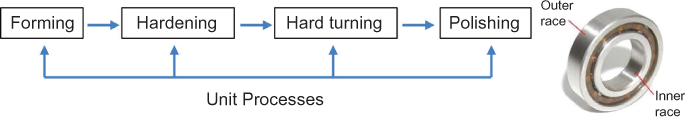
Figure 2.1 Process chain of unit processes to manufacture bearing race.
From the viewpoint of input and output, a unit process may be defined as an area of the process or a piece of equipment where materials are input, a function occurs and materials are output, possibly in a different form, state or composition [2–4]. All manufacturing processes take material inputs, including working materials and auxiliary materials, and transform them into products and wastes. Similarly, the energy inputs into these processes (primarily from electricity) are transformed into useful work, some of which is embodied into the form and composition of the products and wastes, and waste heat. In addition, the energy inputs usually require fuels and produce emissions. For electrical energy inputs, this occurs at the power station. A manufacturing process, along with material and energy flows to and from the process, is diagrammed in Figure 2.2.

Figure 2.2 Energy and material inputs and outputs for unit manufacturing process.
An extensive and continuously expanding variety of manufacturing processes are used to produce parts and there is usually more than one method of manufacturing a part from a given material. The taxonomy of manufacturing processes is illustrated by several versions [2, 5–7], Figure 2.3. These taxonomies have a first level classification of 5 to 6 groups and then these groups are populated by the actual different 120 unit processes.

Figure 2.3 Taxonomy of manufacturing processes.
Even though these unit manufacturing processes are very diverse, they all possess four key operation elements: the work material, the applied energy (mechanical, thermal, or chemical), a localized interaction zone between applied energy/work material, and the process equipment that provides the controlled application of energy. Advances in unit processes can be targeted at any one, or all, of these elements, although usually all four are affected to some extent by a change in any one of the elements. Furthermore, the emerging hybrid manufacturing processes may combine different unit processes working simultaneously on the same work zone within the material to improve manufacturing flexibility and efficiency. Thus, a systems approach is required for improving existing unit processes for developing new ones.
2.2 Life Cycle Inventory (LCI) of Unit Manufacturing Process
Based on a systematic taxonomy of manufacturing unit processes, a worldwide data collection effort is proposed within the CO2PE! UPLCI-initiative. The CO2PE!-Initiative [8] has as an objective to coordinate international efforts aiming to document and analyze the environmental impacts of a wide range of current and emerging manufacturing processes, and to provide guidelines to reduce these impacts. Figure 2.4 gives an overview of the CO2PE UPLCI—framework to collect, document and provide LCI data for a wide range of discrete manufacturing unit processes as well as to identify the potential for environmental improvements of the involved machine tools.
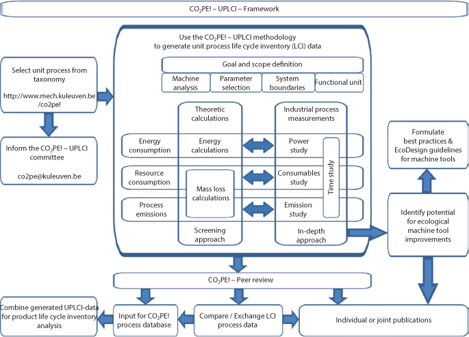
Figure 2.4 Overview of the CO2PE! UPLCI—framework [9].
As shown in Figure 2.4, this data collection can be performed in two different ways and includes an energy, resource and process emission study. The screening approach relies on representative, publicly available data and engineering calculations for energy use, material loss, and identification of variables for improvement, while the in-depth approach is subdivided into four modules, including a time study, a power consumption study, a consumables study and an emissions study, in which all relevant process inputs and outputs are measured and analyzed in detail. The screening approach provides the first insight in the unit process and results in a set of approximate LCI data, which also serve to guide the more detailed and complete in-depth approach leading to more accurate LCI data as well as the identification of potential for energy and resource efficiency improvements of the manufacturing unit process.
In the screening approach (UPLCI, www.wichita.edu/sustainability), data are gathered following the generic methodology for each manufacturing unit process that has been developed by Overcash et al. [10] utilizing the earlier work of Murphy et al. [11], Gutowski et al. [12], EBM [13], and Overcash [13]. The inventory phase is mainly divided in two parts, namely the energy and mass loss calculations [15]. The total energy is determined based on a functional unit output and typically consists of two parts, the direct, incremental energy to accomplish the unit process task (e.g., metal removal in machining) and the fixed energy from auxiliary systems active during idling (partial full mode and standby). Mass losses can be basic materials (such as metal loss from the drilled hole); auxiliary chemicals (such as cutting fluid); off-specification product rejection, etc.
The in-depth approach (http://www.mech.kuleuven.be/co2pe!/taxonomy), whether or not based on the screening approach, may identify focus points for machine tool improvement based on the results that it generates. It includes a time, power, consumables and emission study and leads to more accurate and complete LCI data, and supports the identification of potentials for environmental and economic improvements of the studied manufacturing equipment. Figure 2.5 shows an overview of the process inventory phase for the in-depth approach.

Figure 2.5 Overview of the process inventory phase for the in-depth approach [9].
The Cooperative Effort on Process Emissions in Manufacturing (CO2PE!) has been developed to achieve greater efficiency and quality in producing the fundamental data needed for the UPLCI database. The CO2PE!—template is available to accurately define the goal and scope definition of the intended study, as well as for the dissemination of the unit process inventory results. The collected data for a broad range of manufacturing unit processes will lead to an extensive unit manufacturing process database that can be used by life cycle assessment (LCA) experts, eco designers and product developers for analyzing the environmental impact of individual manufacturing unit processes as well as complete production chains.
2.3 Energy Consumption in Unit Manufacturing Process
2.3.1 Basic Concepts of Energy, Power, and Work
Manufacturing, as a wealth producer, job generator, and human and physical resources user, is the backbone of a country’s growth and development. The manufacturing industry is a key energy consumer, requiring 20% of primary energy (Figure 2.6). The creation of manufactured products that use unit processes must minimize negative environmental impacts, conserve energy and natural resources; be safe for employees, communities, and consumers, and be economically sound.

Figure 2.6 Energy supplies to manufacturing [16].
Before introducing energy consumption in unit processes, it is necessary to clarify several key concepts closely related to energy consumption.
Energy (E): The potential to do work, for example, a force acting through a distance. Energy is a scalar physical quantity and follows the law of conservation of energy.
SI unit: joule (J) = N*m
Other units: kilowatt hour (kWh) = 3.6 million joules, British thermal unit (Btu) = ~1055 joules
Power (P): The rate at which energy is converted. For example, mechanical power is a scalar product of force and velocity.
SI unit: watt (W)
Other unit: Horsepower (HP) = lift 550 pounds by one foot in one second
Work (W): Work is energy expended during a period of time. Work can be done by different energy. For example, work is scalar product of a force times the distance. Since the expended energy = work + wasted energy, work is not equal to energy in many cases.
SI unit: joule (J) = N*m
2.3.2 Framework of Energy Consumption
Energy consumption in unit manufacturing processes can be calculated based on different criteria [17, 18]. Considering the diversity of unit manufacturing processes, a uniform framework of energy consumption would not be feasible. In general, a machining process may have four inventory sectors (Figure 2.7): the processing zone (physical contact) in a unit process, the machine tool (including integral parts of machine tool) to carry out the process, the process periphery (tool changer, coolant system, etc.) to assist performing the process, and the background (heating, ventilation, and air conditioning [HVAC], lighting). The LCI data generated in the zone of physical contact can be measured or calculated theoretically. The calculation of LCI-data generated by machine tool, process peripherals, and background is also required to evaluate the total energy consumption.

Figure 2.7 LCI system boundary of a machining process.
Based on the LCI system boundary, the total energy consumption E in unit manufacturing processes can be determined as follows
where Ep: processing energy, i.e., the energy consumed by the actual material removal which can be given by Ep = ∫ PpdTp, where Pp is processing power and Tp is processing time.
Em: energy consumed by machine tool consists of a number of subsystems which can be turned on individually, which can be given by Em = ∫ PmdT, where Pm is machine power and Tm is machine time.
Epp: process peripheral energy
Ee: background energy, the energy consumed by supporting environment of machine tools, e.g., HVAC, lighting.
The energy in each boundary can be calculated using theoretical models or by integrating the power measured by a power meter. In addition to machining processes, Eq. (2.1) may be modified to fit other unit processes for the evaluation of total energy consumption. Case studies on energy consumption for different unit processes are presented in Section 5, “Energy Accounting in Unit Manufacturing Processes.”
Since the concept of specific energy u is often used in the analysis of unit manufacturing processes, it is necessary to align specific energy with the energy framework of Eq. (2.1). Specific energy is defined as the consumed energy to remove unit volume of material; it is independent of machine tools. It can be calculated as

where Ep is processing energy in Eq. (2.1) and Vm is the total volume of removed material.
Eq. (2.2) can be used to determine specific energy for unit material removal processes such as cutting and grinding for defined material volume. However, specific energy of other unit abrasive processes including honing, lapping, and polishing may not be calculated by Eq. (2.2) because of the non-measurable material volume. Eq. (2.2) may not be used in other unit manufacturing processes like laser forming and welding. For these cases, the absolute value of energy consumption and processing time may be used to evaluate these unit processes.
2.4 Operation Plan Relevance to Energy Consumption
The energy framework was introduced by Gutowski to generally describe unit process energy for all manufacturing processes [12]. Based on thermal equilibrium, the process rate has been identified as the main factor for unit process energy. In addition, machine energy (e.g., control system, lubricants, etc.) and peripheral energy (coolant, etc.) are the other main factors for unit process energy. Due to the different mechanisms of unit processes, it is impossible to enumerate the comprehensive operation conditions relevant to energy consumption for various unit processes. However, it is possible to list the key operation conditions for the representative unit processes to affect energy consumption, as shown in Table 2.1.
Table 2.1a Operation conditions of machining relevant to energy consumption.
| Turning | Milling | Drilling | Grinding | Honing |
| Feed | Feed | Feed | Infeed | Infeed |
| Depth-of-cut | Depth-of-cut | Cutting speed | Wheel speed | Wheel speed |
| Cutting speed | Cutting speed | Drilling length | Work speed | Work speed |
| Cutting length | Cutting length | Drill geometry | Grit geometry | Abrasive grit geometry |
| Tool geometry | Cutter geometry | Coolant | Wheel width | Coolant |
| Coolant | # of cutter tooth | Lubrication | Coolant | Lubrication |
| Lubrication | Coolant | Lubrication | ||
| Lubrication |
Table 2.1b Operation conditions of energy-beam based processes relevant to energy consumption.
| Laser cutting | Laser sintering | Electrical discharge machining (EDM) |
| Laser power | Laser power | Wire feed and speed |
| Laser spot diameter | Laser spot diameter | Voltage |
| Cutting speed | Scan speed | Current |
| Cutting length | Scan length | Dielectric |
| Machining length |
Table 2.1c Operation conditions of forming processes relevant to energy consumption.
| Rolling | Extrusion | Drawing |
| Rolling speed | Ram pressure | Draft |
| Roller diameter | Ram geometry | Drawing speed |
| Work speed | Billet length | Contact length |
| Draft | Die angle | Die angle |
| Rolling length | Part cross-section | Lubrication |
| Lubrication | Lubrication |
2.5 Energy Accounting in Unit Manufacturing Processes
Manufacturing processes are usually driven by electricity energy from fossil fuels, a major CO2 contributor. LCA is an important approach that affects the economics of a product and when combined with existing manufacturing economic models, produces a more complete model. Energy accounting in unit processes improves the energy and environmental burden accounting in the manufacturing of a product. The increasing commodity prices and consumer pressure are driving environmentally conscious business strategy to gain economic advantage through effective energy and cradle-to-grave (i.e., LCA) product management.
A recent survey by Branker et al., [19] on microeconomic cost models reveals that cost components or models can be divided into traditional and nontraditional. Traditional cost models comprise those direct costs associated with manufacturing, often not including energy and environmental considerations explicitly. Reduction of energy and CO2 is an effective way to achieve sustainable manufacturing, and develop more terms and better quantification, thereby approaching a full cost accounting. However, a complete accounting for environmental costs is still lacking in economic models.
Since microeconomic models are concerned at the operation or process level, full cost accounting needs to incorporate costs of theoretical energy (TE) and ancillary energy (AE). Thus, direct and ancillary energy are associated with unit process, while indirect energy is associated with maintaining the operation (plant) environment. In the context of energy classification, Branker et al. [19] developed an economic model of process cost Cp to account for the energy cost and costs of traditional items.
The first four terms Cm, Cs, Cl, and Ct in Eq. (2.3) are traditional costs of machining labor, setup, loading/unloading, and tooling. The direct material cost, CMD, is simply the cost of the material used for the workpiece less the savings of leftover material. Indirect material cost, CMID, is for materials not included in the final product, such as coolant.
CTE is the TE cost related to the minimum energy required to carry out a unit process and the cost of electricity. The energy consumed can be determined in several ways. The energy consumed can be measured, and the electrical cost is known whether it is fixed or varies at the time of use.
CAE is the AE cost related to the ancillary power that is ongoing during the entire operation. It can consist of ancillary or peripheral equipment such as running computers, fans, unloaded motors, and servos.
Cenv is the environmental cost including costs of CO2 emissions, waste (disposal/recycling), and water use.
2.6 Processing Energy in Unit Manufacturing Process
2.6.1 Cases of Processing Energy Modeling
2.6.1.1 Forging
Forging denotes a family of unit manufacturing processes by which plastic deformation of the workpiece is carried out by compressive force. In its simplest form, open-die forging generally involves placing a solid cylindrical workpiece between two flat dies and reducing its height by compressing it, as shown in Figure 2.8.

Figure 2.8 Processing energy model in forging of solid cylindrical workpiece.
Under the conditions without friction between the die/workpiece, the ideal processing energy ![]() to compress a cylindrical workpiece from height h0 to h1 can be calculated as
to compress a cylindrical workpiece from height h0 to h1 can be calculated as
(2.4)
where workpiece volume  specific energy (energy consumed per unit volume compressed)
  and strain
  . The material constants K and n can be found in the literature.
If friction energy Ef between the die/workpiece interfaces and redundant energy Er of material deformation are counted, then actual processing energy Ep will be
(2.5)
2.6.1.2 Orthogonal Cutting
Sources of energy consumption in unit processes vary depending on process mechanisms. The sources in cutting include plastic deformation, friction, surface energy, and momentum transfer. Only the first two of these are significant [20]. Most of the energy dissipated in cutting ends up as heat. The basic chip formation model for cutting is shown in Figure 2.9. Specific energy (energy consumed per unit volume removed) is a very useful concept in cutting. The specific energy u and processing energy Ep in orthogonal cutting can be expressed as

Figure 2.9 Processing energy model for orthogonal cutting.

(2.7)

where Fc, Vc, MRR, b, h, and l are cutting force, cutting speed, material removal rate, width of cut, depth-of-cut, and cutting length, respectively.
Machine energy Em can be determined using power characteristics, i.e., basic power Pbasic and idle or “air-cut” power Pidle. As shown in Figure 2.10, machine energy can be calculated by multiplying the basic or machine utilization time tb and tu with the idle power Pidle and basic power Pbasic, respectively.

Figure 2.10 Power characteristics of machine tools [17].
(2.8)
Basic power Pbasic: It is the power demand under running conditions in “stand-by mode” without relative movement between the tool and the workpiece, but all components that accomplish the readiness for operation (e.g., control, oil pumps) are still running. The basic power is usually a constant for modern CNC machine tools.
Idle/air-cut power Pidle: It is the power for the load case with the relative movement of the tool and the workpiece without machining action.
The process peripherals (such as tool changer, coolant system, etc.) power characteristics specific to the machine location can be determined using a table-lookup method. The peripheral energy Epp can be determined by multiplying with machine utilization time and the amount of power Ppp required by the machine’s periphery.
(2.9)
The background (HVAC and lighting) energy Ee can be determined by multiplying with machine utilization time tu and the amount of background power Pe required by the unit process.
With the determined processing energy Ep, machine energy Em, peripheral energy Epp, and background energy Ee, the total energy consumption of the cutting process E can be calculated according to Eq. (2.1).
2.6.1.3 Grinding
Grinding (Figure 2.11) is a cutting process in microscale. Essentially all of the energy dissipated in grinding ends up as heat. The specific energy u and processing energy Ep in grinding can be expressed as

Figure 2.11 Processing energy model for grinding.

(2.11)

where Fc, Vs, Vw, bw, ae, and l are grinding force, wheel speed, work speed, wheel width, undeformed chip thickness, and grinding distance respectively.
Similar to the case of orthogonal cutting, the total energy consumption of the grinding process E can be calculated.
2.6.1.4 Specific Energy vs. MRR
Shaw [20] found experimentally that cutting speed (Vc) or grinding/wheel speed (Vs) has a relatively small influence on specific energy while the undeformed chip thickness (h) is a dominant parameter when h becomes smaller. In general, specific energy is found to vary exponentially with undeformed chip thickness as follows:
(2.12)

The increase of specific energy (u) with decrease in h in the cutting regime is primarily due to a size effect involving a lower probability of encountering defects on the shear plane as undeformed chip thickness (h) decreases [21].
As shown in Eqs. (2.6) and (2.10), specific energy (u) has an inverse relationship with the MRR. An empirical model of the influence of MRR on specific energy (u) in milling was proposed as follows [22]:
(2.13)

where the constant k essentially has unit of power and constant b represents the steady-state specific energy. Similar empirical models were also reported for turning and milling [23] and grinding [24]. The general relationship between specific energy (u) and MRR for machining at different scales is shown in Figure 2.12.

Figure 2.12 Specific energy as a function of MRR [22].
Although specific energy (u) has an inverse relationship with the material removal rate (MRR), the energy consumed in ultra-precision machining is not necessarily higher than in traditional machining since it is the product of specific energy and removed volume of materials. For precision machining, the removed material volume is much less than traditional machining; the energy consumed in unit precision operation needs to be calculated or measured for case by case.
2.6.2 Energy Measurement
Power consumption in unit processes can also be measured directly. A power meter is usually attached to the main supply of the machine tool to measure the power consumption and calculate the energy consumption of the machine. In a cutting operation, the forces in the process can also be determined via a torque and force dynamometer, as shown in Figure 2.13 and the specific energy is calculated by Eq. (2.2). In an EDM operation, the power consumption is measured for die sinking using a copper tool electrode in combination with a hard metal workpiece [25]. In laser sintering operation, three single phase clamp-on amp meters are often used to measure the currents flowing across the input electrical connections to the three-phase machine. For example, a LabVIEW circuit can be designed to acquire the power data over lengths of operation time. A device is also used for the data acquisition interface to gather the data. This enables acquisition of enough data to observe the trends in power consumption during the various stages of the operation. The same method can be also be used to measure the power consumption of individual subsystems such as those used in Sreenivasan et al., [26].

Figure 2.13 Experimental setup of power measurement [27].
2.7 Energy Reduction Opportunities
The demand for sustainable manufacturing requires high efficiency in using energy and material resources. This demand enables a paradigm change from “maximum profit generated by minimum costs” to “maximum added value derived from minimum resources.” The required performance and the energy and resources efficiency can be achieved via many different routes for the diverse unit processes. In this chapter, metal cutting operations are used as case studies to show opportunities for energy reduction.
Resource efficiency in metal-cutting manufacturing means, in terms of a specific component, primarily a reduction of energy consumption along the complete process chain. In view of the fact that the overall energy consumption of the machine tool and the cooling system exceeds several times the energy used for the metal cutting process, the following opportunities are considered, investigated and implemented [28].
- Shortening process chain
- Substitutions of process steps
- Using hybrid processes
- Adaptation of cooling and flushing strategies
- Adopting remanufacturing
The developments of machine tools and adaptronic options, as well as product utilization, are beyond the scope of the chapter.
2.7.1 Shortening Process Chain by Hard Machining
Shortening the process chain is an effective way of reducing energy consumption in manufacturing (Figure 2.14). One example of shortening the traditional process chain of mold manufacturing is to substitute grinding by hard milling. In addition, the new process chain will significantly reduce energy consumption since specific energy in cutting is significantly less than grinding [29].

Figure 2.14 Process chain shortened by hard milling.
2.7.2 Substitution of Process Steps
Machining of hardened steels is often limited to long and expensive processes such as electrical discharge machining (EDM) and grinding. A typical example is the production of dies and moulds for various industries shown in Figure 2.15. Requirements set by the complex shapes, deep cavities, and larger overcuts, high accuracy and very specific surface integrity properties can be fulfilled today by machining with newly designed cutting tools, new cutting tool materials like cubic boron nitride (CBN) and poly-crystalline diamond (PCD), and state-of-the-art machining strategies, machines, and adaptronic systems.

Figure 2.15 Increase of energy efficiency by using new technologies [28].
2.7.3 Hybrid Processes
Hybrid manufacturing processes are based on the simultaneous and controlled interaction of process mechanisms and/or energy sources/tools having significant performance. Example are cutting or grinding with additional simultaneous ultrasonic vibration or, by turning and grooving of high temperature alloys to use high pressure flushing, which is acting as a “chip breaker” or “chip former” in addition to its effects of cooling and reduction of friction for improved cost, resources and energy efficiency. Investigations are also carried out combining, for example, laser assisted turning (Figure 2.16) [30], thus eliminating more expensive processes like very fine finishing or grinding.

Figure 2.16 Hybrid milling-laser process.
2.7.4 Adaptation of Cooling and Flushing Strategies
Machining with high pressure flushing is only energy efficient for certain applications and materials. The appropriate use of cooling systems cannot only significantly increase productivity but also help to decrease energy consumption during cutting operations. This includes dry cutting and cutting with minimum quantity lubrication (MQL), where certain work-piece material compositions are concerned. Cryogenic cooling with liquid nitrogen or dry ice is also practical for machining superalloys. Special requirements in regard to the thermal load capability and stability of tools, workpieces, and machine tools, as well as chip evacuation, will in turn need to be met so as to guarantee a reliable process [28].
2.7.5 Remanufacturing
According to a recent survey by Gutowski [31], remanufacturing is recognized as the preferred option (in many references) for end-of-life product. The obvious benefits are that remanufacturing can generally save some (usually large) portion of the invested energy used in both the materials production as well as the manufacturing (the assumption is usually made that the remanufactured product is a substitute for a new product). However, energy saving may not always be in favor of remanufacturing. The result depends heavily on whether the product has an energy-intensive use phase.
References
1. Guo Y.B. and D.W. Yen, Hard Turning Versus Grinding – The Effect of Process-Induced Residual Stress on Rolling Contact, Wear, 256(3–4), pp. 393–399, 2004.
2. Todd R.H., D.K. Allen and L. Alting, Fundamental Principles of Manufacturing Processes, Industrial Press Inc., New York, 1994.
3. Choi A.C.K., H. Kaebernick and W.H. Lai, Manufacturing Processes Modelling for Environmental Impact Assessment, Journal of Materials Processing Technology, 70(1–3), p. 231–238, 1997.
4. Bandivadekar A.P., V. Kumar, K.L. Gunter and J.W. Sutherland, A Model for Material Flows and Economic Exchanges Within the U.S. Automotive Life Cycle Chain, Journal of Manufacturing Systems.
5. Kalpakjian S., and S. Schmid, Manufacturing Processes for Engineering Materials, 3rd edition, Addison-Wesley, 1997.
6. Gay J. (ed.), Introduction and Applications of DIN 8580 (English) di Girona Publications, Girona, Spain, 2007.
7. National Research Council (NRC), Unit Manufacturing Processes: Issues and Opportunities in Research, National Academy Press, Washington D.C., 1995.
8. CO2PE!, 2011, Cooperative Effort on Process Emissions in Manufacturing Website. http://www.mech.kuleuven.be/co2pe. Accessed, July 2011.
9. Kellens K., W. Dewulf, M. Overcash, M.Z. Hauschild and J.R. Duflou, Methodology for Systematic Analysis and Improvement of Manufacturing Unit Process Life-Cycle Inventory (UPLCI) —CO2PE! Initiative (Cooperative Effort on Process Emissions in Manufacturing). Part 1: Methodology Description, The International Journal of Life Cycle Assessment, 17(1), pp. 69–78, 2012.
10. Overcash M., J. Twomey and D. Kalla, Unit Process Life Cycle Inventory for Product Manufacturing Operations. In: ASME International Manufacturing Science and Engineering Conference, West Lafayette, IN, USA., 2009.
11. Murphy C., G. Denig, D. Allen, J. Laurent and D. Dyer, Development of Parametric Material, Energy, and Emission Inventories for Wafer Fabrication in the Semiconductor Industry. Environmental Science & Technology, 37(23), p. 5373–5382, 2003.
12. Gutowski T., J. Dahmus, and A. Thiriez, Electrical Energy Requirements for Manufacturing Processes. In: Proceedings 13th CIRP international conference on life cycle engineering, Leuven, 623–628, 2006.
13. EBM, 2010, Environmentally Benign Manufacturing: online Publication List. Massachusetts Inst of Technology (MIT). 2010.
14. Overcash M., Evolving Concepts in Life Cycle Analyses. In: Cleaner technologies and cleaner products for sustainable development. NATO ASI Series. Springer, New York, p. 455–470, 1995.
15. UPLCI, Online Database and Taxonomy (Screening Approach). Available from www.wichita,edu/sustainability. Accessed 9 July 2011, 2011.
16. Jeswiet J. and S. Kara, Carbon Emissions and CES™ In Manufacturing, CIRP Annals - Manufacturing Technology, 57(1), p. 17–20 2008.
17. Abele E., Anderl R. and H. Birkhofer, Environmentally-Friendly Product Development Methods and Tools, Springer London, 2004.
18. Rahimifard S., Y. Seow and T. Childs, Minimising Embodied Product Energy to Support Energy Efficient Manufacturing, CIRP Annals - Manufacturing Technology, 59(1), p. 25–28, 2010.
19. Branker K., J. Jeswiet and I.M. Kim, Greenhouse Gases Emitted in Manufacturing a Product - A New Economic Model, CIRP Annals - Manufacturing Technology, 60(1), 53–56, 2011.
20. Shaw M.C., Energy Conversion in Cutting and Grinding, CIRP Annals - Manufacturing Technology, 45(1), 101–104, 1996.
21. Shaw M.C., A Quantized Theory of Strain Hardening as Applied to The Cutting of Metals, Journal of Applied Physics, 21(6), p. 599–606, 1950.
22. Diaz A., E. Redelsheimer and A. Dornfeld, Energy Conversion Characterization and Reduction Strategies for Milling Machine Tool Use, In: Proc. of 18th CIRP International Conference on LCE, Brauschweig, 2011.
23. Kara A. and W. Li, Unit Process Energy Consumption Models for Material Removal Processes, CIRP Annals - Manufacturing Technology, 60(1), p. 37–40, 2011.
24. Li W., M. Winter, S. Kara and C. Herrmann, Eco-Efficiency of Manufacturing Processes: A Grinding Case. CIRP Annals - Manufacturing Technology, 61(1), 59–62, 2012.
25. Kellens K., Renaldi, W. Dewulf and J.R. Duflou, Preliminary Environmental Assessment of Electrical Discharge Machining, In: Proc. of 18th CIRP International Conference on LCE, Brauschweig, 2011.
26. Sreenivasan R., A. Goel and D.L. Bourell, Sustainability Issues in Laser-Based Additive Manufacturing, Physics Procedia, 5(A), p. 81–90, 2010.
27. Neugebauer R., A. Schubert, B. Reichmann and M. Dix, Influence Exerted by Tool Properties on The Energy Efficiency During Drilling and Turning Operations, CIRP Journal of Manufacturing Science and Technology, 4(2), p. 161–169. 2011.
28. Neugebauer R., R. Wertheim and C. Harzbecker, Energy and Resources Efficiency, Springer-Verlag Berlin, Heidelberg, 2011.
29. Zhang S. and Y.B. Guo, Taguchi Method Based Process Space for Optimal Surface Topography by Finish Hard Milling, Journal of Manufacturing Science and Engineering, 131(05), p. 051003, 2009.
30. Nau B., A. Roderburg and F. Klocke, Ramp-up of Hybrid Manufacturing Technologies, CIRP Journal of Manufacturing Science and Technology, 4(3), p. 313–316, 2011.
31. Gutowski T., Manufacturing and the Science of Sustainability, In: Proc. of 18th CIRP International Conference on LCE, Brauschweig, 2011.