Application of a New Vacuum Preloading Method for Tideland Reclamation in Wenzhou, China
Yuang-qiang Cai; Jun Wang; Jian-jun Ma College of Architecture and Civil Engineering, Wenzhou University, Wenzhou, China
Abstract
A new vacuum preloading method was used for one phase of a large tideland reclamation program, the Oufei project, in Wenzhou, China. This new vacuum preloading approach, the multiple-vacuum preloading method, combines a vacuum preloading system and a pressurization system. The former is equipped with anticlogging prefabricated vertical drains (PVDs), which prevents clogging around PVDs and facilitates vacuum pressure to be transferred to deep soil layers. The latter is applied to enhance the permeability of subsoils and to allow more effective drainage of water out of subsoils. A comprehensive instrumentation program was adopted to monitor the performance of the ground improvement. The improvement achieved in this project was evaluated with further discussion on the mechanisms of the vacuum preloading method and estimation of degree of consolidation.
14.1 Introduction
As a result of rapid economy development in Wenzhou, China and its booming population, more land is required to implement a variety of infrastructures, including residential and commercial buildings, pavements, railways, and an airport. The Oufei project in Wenzhou is the biggest tideland reclamation program in China. It was approved in 2004 by the state government to reclaim a total area of 448 km2 along the eastern seaboard, as shown in Fig. 14.1.

In the Oufei project, many phases have been scheduled according to their seabed levels and the required depths of fill materials. The fill materials used for this project are mainly clay slurry dredged from the nearby seabed. After several years of deposition and sedimentation, the soil particles of the dredged marine slurry have settled in the reclaimed area with a depth of more than 10 m. The dredged slurry is typically characterized by high water content, high compressibility, low undrained shear strength, low coefficient of consolidation, low penetrability, and so on (Chu et al., 2000; Yan et al., 2010). Thus, the main challenge encountered in these engineering activities is how to save the consolidation time and how to improve the consolidation effectiveness with a reasonable cost.
Due to the extremely low strength of dredged fill, pretreatment is needed before applying heavy machines to carry out improvement work with high preload. Thus, lower preload is applied to achieve the pretreatment. In most tideland reclamation projects, the most common and effective approach to increase consolidation rate is to use the vacuum preloading method (Kjellman, 1952). Generally, a vacuum pressure of up to 90 kPa (normally above 80 kPa) can be applied and maintained as long as it is required. According to Chu et al. (2000), for an equivalent loading, the vacuum preloading method is cheaper and faster when comparing with fill surcharge. It has been used in numerous soil improvement projects around the world (Holtan, 1965; Chu et al., 2000; Bergado et al., 2002; Chu et al., 2004; Chu and Yan, 2005a,b; Seah, 2006).
The mechanism of vacuum preloading has been discussed extensively by many investigators; for example, see Kjellman (1952), Holtz and Wager (1975), Qian et al. (1992), and Chu and Yan (2005a,b). For the vacuum preloading method, the increase in effective stress is directly due to the suction (negative) pressure, while maintaining the same total stress (Chu and Yan, 2005a,b). The general characteristics of vacuum preloading in comparison with conventional fill surcharge preloading are also discussed in the literature (Qian et al., 1992; Chu et al., 2000; Chai et al., 2005; Chu and Yan, 2005a,b). Note that the two methods lead to the same goal: dissipation of pore water pressure and increase in effective stress. Generally, the adoption of the preloading method would also be based on the budget, required preloading, construction period limit, manpower, soil properties, and environmental issues. However, for extra soft soil, such as dredged fill in the Oufei project, vacuum preloading method is the best option due to the inability to apply a large amount of fill surcharge on soft ground.
This chapter presents a case study of the application of a new vacuum preloading method, the multiple-vacuum preloading method, in one phase of the Oufei project in Wenzhou, China. The multiple-vacuum preloading method is a combination of a vacuum preloading system and a pressurization system. The improvement of this vacuum preloading system is the anticlogging prefabricated vertical drains (PVDs), which can effectively prevent clogging around the PVDs and transfer vacuum pressure to deep soil layers. The pressurization system is designed to enhance the permeability of the submarine clay and to increase the pore pressure around the PVDs, thus draining water out of subsoils more effectively. The new vacuum preloading approach and the soil improvement procedure are described. Based on the monitoring data, the effective depth of vacuum preloading is discussed and the degree of consolidation is estimated.
14.2 Subsoil conditions
Phase X is situated on the Quaternary deposit with a depth of 100 m; the thickness of the soft soil layer is more than 50 m. Comprehensive soil investigations were carried out onsite, and these showed that the subsoil consists of dredged fill with a thickness of around 27 m, extending to a silty clay at depths of 27–42 m, followed by medium stiff clay (up to 50 m deep). The top marine clay consolidated from dredged fill is further divided into five subsoil layers according to Chinese design code: a very soft, low plasticity and flowing muddy layer of 0.3–0.5 m thick; a low plasticity clay layer of 0.5–1.8 m thick; a low plasticity silty clay with a total thickness of around 4.7 m; a low-to-medium plasticity silty clay within the depth of 7–22.8 m; and a layer of medium plasticity clay of 4.8 m thick, which also contains some silt.
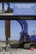
The main components of the top dredger fill are muddy clay and silty clay. Typical soil properties including liquid limit (wL), plastic limit (wP), water content (w), degree of saturation (Sr), unit weight (γ), void ratio (e), and undrained shear strength (cu) profiles are plotted in Fig. 14.2. As the water content throughout soil depth was much higher than the liquid limit, the vane shear strengths of soils were extremely low and the coefficients of consolidation from oedometer tests are in the range of 0.80–1.25 cm2/s.

Note that the soil beneath this improvement zone was very soft with high water content (most dredged fill clay exceeds the liquid limit) and its undrained shear strength was generally low. Thus, manmade gravel sand mixture (around 0.5 m thick) was placed on the surface to accommodate the improvement work.
14.3 Soil improvement procedure
14.3.1 Multiple-vacuum preloading method
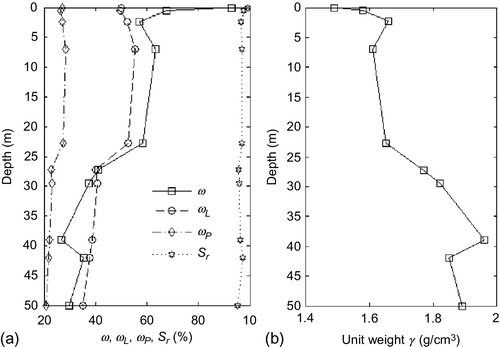
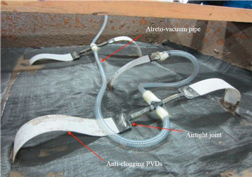
After a comprehensive survey in Wenzhou, it was found that the conventional vacuum preloading method encountered many problems in engineering application, including clogging in PVDs, vacuum loss along the length of drains, insufficient consolidation in deep soil layer, and excessive settlement after construction (Cai et al., 2014). These problems can lead to accidents such as severe ground settlement, pile foundation tilting, pipeline cracking, and construction machine sinking. Thus, a new method, namely the multiple-vacuum preloading method (Cai et al., 2014), was applied to consolidate the dredged fill in the tideland reclamation area: Phase X. Two main systems are included in this approach: the vacuum preloading system and the pressurization system. Considering the main characteristics of dredger fill, two main innovations—anticlogging-integrated PVDs (Fig. 14.3) and a horizontal airtight connection mode (Fig. 14.4)—are integrated into the vacuum preloading system. The pressurization system is a combination of a booster pump and pressurization tubes (Fig. 14.5), which enhance permeability in the smear zone and increase pore pressures around PVDs, thereby improving consolidation degree in the deep subsoil layer.

PVDs
In the anticlogging-integrated PVD adopted in this project, the filter and board core are adhered together through heat melting, thus forming an integrated body (see Fig. 14.3). The board core is also made of polypropylene plastic, which is free of deformation. The filter is made of nonwoven filter cloth in a flat shape, thereby improving anticlogging capacity and crack resistance. In addition, hydrophilic material (i.e., bamboo fiber) is mixed with the filter to enhance the effectiveness of drainage.
The opening size (O95, the size for 95% of passing particle by weight) of PVDs is about 120 μm, which meets the common design criteria proposed by Carroll (1983). D85 (the size for 85% of passing particle by weight) is about 80 μm for the dredge fill on Wenzhou coast.
Horizontal drainage system
In the conventional vacuum preloading method, corrugated filter pipes 50 mm in diameter are normally used for horizontal drainage. This approach is simple and effective for shallow soil layers. However, the application of vacuum pressure in deeper soil layers may be weak due to the loss of vacuum (Indraratna et al., 2004). In the multiple-vacuum preloading method, atreto-vacuum pipes (see Fig. 14.4) are used to reduce the loss of vacuum and the deformation of horizontal drain channels. Also, the anticlogging-integrated PVDs are connected directly to the atreto-vacuum pipes through airtight joints. This cuts down the vacuum loss at the connection between the PVDs and horizontal pipes. Laboratory tests (Cai et al., 2014) have shown that this arrangement is more effective than the conventional method.
Pressurization system
The pressurization system combines a booster pump with pressurization tubes (see Fig. 14.5), with the main aim of enhancing the permeability in the smear zone and increase pore pressures around the PVDs.
14.3.2 Case History
The multiple-vacuum preloading method that was used for Phase X of the Oufei land reclamation project was for the foundation for a water lock. The layout of the soil improvement area is shown in Fig. 14.6. The total area was 3200 m2 and the water level was above the muddy clay slurry. A photo of the soil improvement work is shown in Fig. 14.7. The major concern of this project was how to consolidate the soft soil layer with a total depth of around 20 m. Although successful cases have been presented (Chu et al., 2000), the conventional vacuum preloading method was found to be not always effective for deep soils in Wenzhou. Thus, this project was an attempt to evaluate the effectiveness of the new multiple-vacuum preloading method.


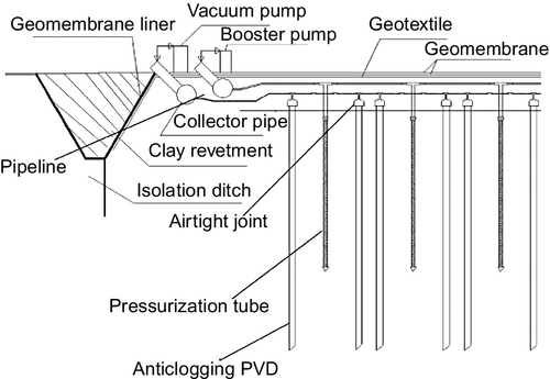
A schematic diagram of the new vacuum preloading method applied in this project is shown in Fig. 14.8. The procedure of the multiple-vacuum preloading method applied in this project is as follows.
Pretreatment
As the top soil was too soft to carry out improvement work, a sandy gravel cushion with a total thickness of 0.5 m was placed on the improvement zone first.
Installation of anticlogging-integrated PVDs and pressurization system
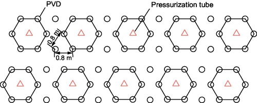
Anticlogging-integrated PVDs were then installed along triangle grids with a spacing of 0.8 m and depth of 20 m. Later, the pressurization tubes were installed in the center of a regular hexagon formed by PVDs (Fig. 14.9), and the depth of these embedded pressurization tubes was also 20 m. Thereafter, the upper ends of these anticlogging-integrated PVDs were connected to airtight vacuum pipes through airtight joints; and the pressurization tubes were linked to a booster pump by long soft hoses (Fig. 14.8).
Installation of sealing system
It was required that the site be firmly sealed, thus, two layers of sealed geomembrane were placed on the top surface, as shown in Fig. 14.8. A flexible sealed geomembrane covered the treatment area and was keyed into an anchor ditch and sealed off by clay revetment.
Instrumentations
Instruments including pore water pressure transducers, surface settlement plates, inclinometer, and multilevel settlement gauges were installed in the treatment zone to monitor consolidation performance. The layout of the installed instruments was shown earlier in Fig. 14.6.
Vacuum preloading and pressurization
A vacuum pressure of 80 kPa over an area of 3200 m2 was applied and maintained for a period of more than 90 days. When the average settlement for a consecutive period of 10 days was less than 2 mm/day, the booster pump started running, with a positive pressure of 20 kPa maintained for at least 15 days to ensure that the required degree of consolidation was achieved.
14.4 Monitored data
During vacuum preloading, surface settlement, multisoil layer settlement, and pore water pressure with time were monitored. After preloading, field shear tests were conducted at one specific region (see Fig. 14.6) with three different testing points: near the PVD, near the pressurization tube, and in the middle of PVD and pressurization tube. The results of the monitored data and testing results are analyzed in the following. Note that the settlement and pore water changes due to the placement of the sandy gravel cushion and the installation of PVDs and pressurization tubes are not included in this analysis.
14.4.1 Settlement
The recorded surface settlement versus time curves for different monitored points (S1, S2, and S3) are plotted in Fig. 14.10. This improvement work lasted 94 days; the pressurization started working after 56 days’ vacuum preloading. Note that in three monitoring sites, the majority settlements (more than 80%) were achieved within the first 56 days; with the help of pressurization, further settlement was observed for this improvement area. As shown in Fig. 14.10, the faster settlement rate achieved in the final period (the last 30 days) was contributed by the pressurization system. This can be explained by two main functions of the pressurization system: (1) in the vicinity of the pressurization tubes, many bubbles with high air pressure (up to 20 KPa) generated by the booster pump pushed the pore water toward the PVDs and eventually enhanced the discharge of pore water pressure; (2) these bubbles compressed and rearranged the surrounding soil particles, as well as piercing into some soil layers with high density and extremely low permeability, thereby enhancing the permeability of smear zones. Thus, the pressurization technology served as an effective method for soil improvement in the last period.

In addition, the divergence of settlement occurred after five days of preloading. The surface settlement at S2, however, is smaller than that of the other two sites (S1 and S3, in the middle of the square). This may be due to the divergence of the soil properties in this treatment area, as understood by most geotechnical engineers.
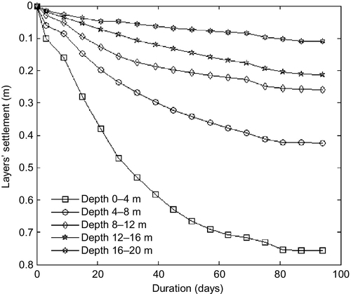
Five soil layers’ settlements, 0–4 m, 4–8 m, 8–12 m, 12–16 m, and 16–20 m depth are plotted in Fig. 14.11. Obviously, the top soil was found to have more settlement compared to deep soil layers. Similar to the surface soil layer, the major settlements were accomplished in the first 56 days. This indicates that the vacuum preloading method works effectively and treats soil quickly in the first two months. The further settlement was achieved with the help of pressurization and vacuum pressure, accounting for around 20% of the total settlement.
14.4.2 Pore water pressure drop
With the help of multiple-vacuum preloading, the pore water in the improvement zone section (with four different depths: 5 m, 10 m, 15 m, and 20 m) reduced significantly, as shown in Fig. 14.12. In shallow soil layer (5 m deep), the pore water pressure changed from 53 kPa to − 25 kPa; note that after 50 days, the water pressure state remained negative until the end of the improvement work. In deep soil layers (20 m), pore water pressure dropped from 200 kPa (before preloading) to 140 kPa (after preloading), with a total reduction of 60 kPa.

The variation in pore water pressure against time for different depths of the monitored point demonstrates that the vacuum pressure can work effectively at depths greater than 10 m, indicating the effectiveness of vacuum preloading throughout the entire depth. The deep transmission of vacuum pressure is due to the anticlogging-integrated PVDs and the airtight joints that connect the horizontal pipes and PVDs. It also proves that the multiple-vacuum preloading method can minimize the vacuum loss along horizontal pipes, and therefore transfer vacuum pressure to deep soil layers (up to 20 m).
Note that the reduction in pore water pressure along the depth dropped gradually, from 78 kPa in 5 m deep to around 60 kPa at a depth of 20 m. This observation further indicates the effectiveness of vacuum pressure transmission in deep soil layers.
14.4.3 Field vane shear tests
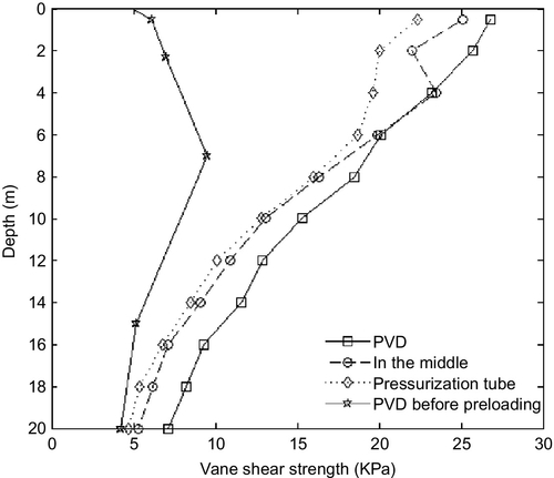
After vacuum preloading, field vane shear tests were conducted at one specific area (shown in Fig. 14.6) with three testing points: near the PVD, in the middle of the PVD and pressurization tube, and near the pressurization tube. Due to some unexpected reasons, field vane shear tests were only conduced at the site of PVD before preloading. Thus, undrained shear strength obtained before and after preloading can only be compared for the site with the PVD. As can be seen in Fig. 14.13, the undrained shear strength of the improvement zone increased 2–3 times in relatively shallow layers (~ 12 m deep) and 1–1.5 times in deep soils (below 12 m). Meanwhile, the vane shear strength of consolidated dredger fill around the PVD was higher (more than 2 kPa) than that of the two sites. This may be due to the higher density of the treated dredged fill, as the smear zone has been found around PVDs.
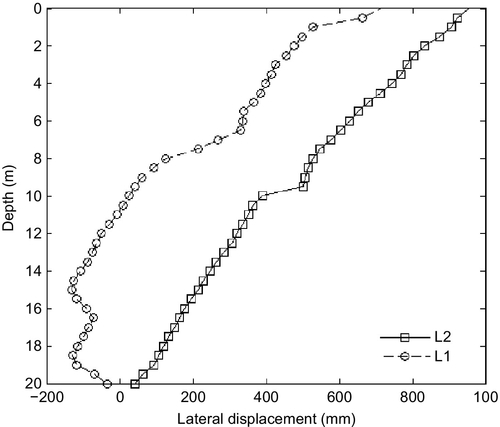
14.4.4 Lateral displacement
After the vacuum preloading, the final lateral displacements (west border L1 and north border L2) with depth were recorded and plotted, as shown in Fig. 14.14. For both sites, the lateral displacement achieved the largest value at the surface level (0.6 m for the west border and 0.95 m for the north border), however, the lateral displacement reduced dramatically from ground surface to deep soil layers. Generally, the lateral displacement tends inward (left side of the displacement axis, or positive side), however, due to some uncertain soil properties and geological features beneath the improvement zone, the lateral displacement that occurred at the west border tended outward within the depth of 8 m. This uncertainty drew our attentions for further site investigation.
14.5 Evaluation of degree of consolidation
In soil improvement work, engineers and investigators are generally concerned with the effective depth of the multiple-vacuum preloading method. In this project, as shown earlier in Fig. 14.12, the vacuum pressure is effective at depths greater than 10 m, and the pore water pressure is reduced in much deeper soil layers (up to 20 m); the pore water pressure dropped to around 60 kPa at a depth of 20 m. This is due to the contribution of two innovations of the vacuum preloading system: the anticlogging PVDs and the airtight joints connecting the PVDs and horizontal drainage pipes.
The mechanism of the pore water pressure drop and consolidation of dredged fill is explained in Chu et al. (2000). Two main processes are involved in consolidation of soft soil by using the vacuum preloading method: (1) the water is pumped out from soil through PVDs (this only works at depths of less than 10 m), and (2) pore water pressure is reduced to increase the effective stress. Note that with the help of a pressurization system, the permeability of subsoils is enhanced and the improvement on water pumping has been achieved. Thus, this new approach accommodates the soil improvement work effectively and the mechanism of this approach is line with the Terzaghi’s consolidation theory.
Another common concern in soil improvement work is the degree of consolidation (DOC), which is defined as the ratio of current settlement over the ultimate settlement. Normally, the value of ultimate final settlement is unknown as the secondary consolidation will take longer than the primary one, therefore this value needs to be predicted. In this project, the ultimate settlement is estimated using the method of Zeng et al. (1981):
where, ![]() is the ultimate settlement, with three time intervals, t1, t2, and t3 being chosen from the settlement-time curve (
is the ultimate settlement, with three time intervals, t1, t2, and t3 being chosen from the settlement-time curve (![]() ); the corresponding settlements are S1,S2, and S3, respectively. Applying Eq. (14.1), the estimated DOCs for different measured points are shown in Fig. 14.15.
); the corresponding settlements are S1,S2, and S3, respectively. Applying Eq. (14.1), the estimated DOCs for different measured points are shown in Fig. 14.15.

Note that the DOCs estimated for the improvement zone meet the designed requirement: more than 90% of the settlement was achieved within three months. For the concern of safety and feasibility, measurements and monitoring still need to be continued for a further three months. Comparing the pore water variation curve in Fig. 14.12 and the DOCs curve in Fig. 14.15, it is worth noting that with a drop in water pressure, the effective stress increased accordingly, thus, the soils were consolidated. The variation of pore water pressure drops and their corresponding subsoil layers’ settlements were in good agreement. This demonstrates that the effective stress theory can be applied to explain the basic mechanism of the vacuum preloading method.
It is also worth noting that the consolidation contributed by the pressurization system (shown in Figs. 14.10 and 14.11) is valuable. After 56 days, 80% of the total settlement was achieved and the settlement rate was less than 2 mm/day. With the help of the pressurization system, this rate was enhanced and around 20% settlement was obtained in the last 30 days. This enhancement is directly due to the increment in the permeability of dredged fill around PVDs (Cai et al., 2014), also partially owing to the rise in pore water pressure around PVDs (Fig. 14.12).
Field vane shear strength tests further demonstrated the improvement effect achieved in this project with the application of the multiple-vacuum preloading method. After treatment, the undrained shear strength increased more than 3-fold and 1.5-fold in shallow (10 m) and deep soil layers (10–20 m), respectively.
14.6 Conclusion
The application of the multiple-vacuum preloading method in soil improvement for Phase X in the Oufei project, Wenzhou was studied. It was found that the vacuum pressure as effective for up to 20 m. The degree of consolidation achieved at the improvement zone met the requirement of more than 90% in three months. This case study demonstrated that the multiple-vacuum preloading method was effective for consolidating the dredged clay slurry fill used for land reclamation in Wenzhou, China.