Pullout Resistance of Grouted Soil Nails
Wan-Huan Zhou Department of Civil and Environmental Engineering, Faculty of Science and Technology, University of Macau, Macau, China
Abstract
Soil nailing is a technique accomplished by installing closely spaced, passive, structural inclusions, known as nails, into the soil to increase its overall shear strength. Soil nails have been widely used for stabilization of slopes and earth-retaining structures in many countries and regions. In Hong Kong, grouted soil nails have been used in most slope stabilization works since the late 1980s. Although the design guidelines are available in many countries, some design issues remain ambiguous among some engineers and researchers. The soil nail ultimate pullout resistance is a key parameter for the design of soil nails. Many of the issues under debate are related to the determination of this key parameter. Some influencing factors are not well qualified in the current design methods. For example, the effective stress method, adopted in Hong Kong, does not account for factors including soil arching, soil dilatancy, soil saturation condition, roughness of drill-hole surface, and grouting pressure. Better design can be achieved if the pullout resistance of grouted soil nails is more accurately predicted. In this chapter, the behavior and design methods of the soil-nailing system are first reviewed. Different methods for determination of soil nail pullout resistance are discussed. Then, the technique and test procedures for laboratory pullout testing of grouted soil nails under controlled overburden pressure, degrees of saturation, and grouting pressure are recounted. Next, based on the series of laboratory pullout tests, the effects of some key factors on the pullout resistance of grouted soil nails are systematically discussed. These factors include overburden pressure, degree of saturation, and grouting pressure in both unsaturated and saturated conditions. Finally, a probabilistic estimation of the pullout resistance of grouted soil nail is reviewed. By using the Bayesian model class selection approach and all the pullout resistance data from laboratory tests, an optimal formula is proposed and it possesses rational balance between the data-fitting capability and robustness to measurement noise and modeling error. It is found that the most important factors in the estimation of soil nail pullout resistance are the degree of saturation and the product of grouting pressure and overburden pressure.
Acknowledgments
The author would like to express deepest gratitude to Prof. Jian-Hua Yin (The Hong Kong Polytechnic University) for his support and guidance on the laboratory soil nail pullout tests. Gratitude is extended to Professor Ka-Veng Yuen (University of Macau) and Miss Tan Fang (University of Macau) for their contributions on the Bayesian analysis in this chapter. The author would also like to acknowledge the financial support from the Macau Science and Technology Development Fund (FDCT/011/2013/A1 and FDCT/125/2014/A3) and the University of Macau Research Funds (MYRG2014-00175-FST, MYRG2015-00112-FST, MYRG067(Y2-L2)FST12-ZWH).
20.1 Introduction
Soil nailing is a technique used to reinforce and strengthen existing ground conditions. This is accomplished by installing closely spaced, passive, structural inclusions, known as nails, into the soils to increase their overall shear strength. During the 1970s, the soil-nailing technique was developed in France, Germany, and the United States. Thereafter, the technique has been increasingly used in soil reinforcement projects all over the world.
The first recorded application of soil nailing appeared in France in 1972 when a soil-nailed wall was built at Versailles in France for the widening of a railway cutting (Schlosser et al., 1992). In 1986, a major French national research project Clouterre (Clouterre, 1991) was initiated. The Clouterre program involved three large-scale experimental walls in prepared fill and the monitoring of six full-scale in-service structures. The results of the projects led to the development of the French method for the design of soil nails. Known as the multifailure criteria, it provides an option to consider the bending resistance of the soil nail in design.
Though the first “modern” soil-nailing structures were constructed in France, it was in Germany that the first comprehensive research project into soil nailing was undertaken (Gässler, 1987,1988). The Bodenvernagelung (the German term of “soil nailing”) project was carried out by the University of Karlsruhe and the contractor Bauer from 1975–1981. This four-year program included seven full-scale instrumented field tests accompanied by model laboratory tests and theoretical research. The observations and results from Bodenvernagelung project led to a limit equilibrium method for the design of soil-nailed walls using a bilinear failure surface. This is known as the “German method.” It considers only the contribution of axial resistance of the nails to the stability of the structure.
Research in the United States initially developed independent of that in Europe, under a technique described as the lateral earth support system. This research was conducted primarily at the University of Davis by Bang et al. (1980). The project incorporated centrifuge model studies, a full-scale instrumented construction, and field measurements. In addition, finite element studies were conducted to simulate the centrifuge models. The Davis method of design was formulated from this research (Bang et al., 1980), using a limit equilibrium method, whereby the failure plane is described by a parabola. The method of analysis considered only the axial contribution of the nails to maintain the stability of the structure.
Following this research at the University of Davis, a number of projects included instrumentation of the soil nails and monitoring of movements. Juran et al. (1990) proposed a limit equilibrium method using the kinematically admissible log spiral, incorporating an option to include nail-bending resistance in the design similar to that used in the French method. In 1996, the U.S. Federal Highway Administration (FHWA) published the Manual for Design and Construction Monitoring of Soil Nail Walls. It gives guidance for a design method considering only the contribution of tensile resistance of the nail to the stability of the structure, but leaves selection of failure planes up to the experience of the engineer. Soil nailing has been found to be the most cost-effective method for larger projects that require considerable excavation using conventional methods (FHWA, 1996).
Much research on soil nailing has taken place at universities in the United Kingdom. The research topics include: the importance of bending and shear relative to tensile resistance in soil nails (Jewell and Pedley, 1990, 1992); the influencing factors on pullout resistance of soil nails in sand and clay (Milligan et al., 1997; Milligan and Tei, 1998); centrifuge modeling of slopes stabilized using soil nailing (Gammage, 1997; Aminfar, 1998); ground/soil nail interaction from large shear box tests (Barr et al., 1991; Davies and Le Masurier, 1997); and finite element modeling of soil-nailing construction (Ho and Smith, 1993; Smith and Su, 1997). In 2002, more than 60,000 m2 face area of soil nailing were installed in the United Kingdom. The use of soil nails has become widespread, from stabilization of existing retaining walls and slopes to construction of new steep slopes and retaining walls.
Soil nailing was extensively used in Japan in the late 1990s. Sano et al. (1988) proposed design methods for reinforced cut slopes. Chai and Hayashi (2005) introduced a combined technology of chemical grouting and soil nailing called the earth sewing technique. The contribution of constrained dilatancy to the nail pullout resistance in an unsaturated sandy clay was studied.
In Australia, the first application of soil nailing was reported in 1992 where the procedure was used to stabilize a road embankment, constructed of silty sands, north of Sydney (Seto et al., 1992). A limit equilibrium design method using a circular slip analysis was used and verified by pullout tests. Three nails were strain gauged and monitored for 1.7 years to assess the performance of the nails. Results showed a small but gradual increase in force developed in the nail with no more movement of the embankment.
The soil-nailing technique was introduced to Hong Kong in the 1980s. Due to the advantages of simplicity, speed construction, and economical efficiency, soil nailing has been increasingly used and has become the most common slope stabilization method in Hong Kong. Each year more than 200 slopes and retaining walls have been upgraded using soil nails (GEO, 2008). Most soil-nailing works in Hong Kong are associated with the stabilization of existing soil-cut slopes and retaining walls. They are also used for reinforcing new soil-cut slopes, existing fill slopes, disturbed terrain, and natural hillsides. The use of soil nails in new retaining walls and new fill slopes is rare in Hong Kong. Apart from permanent works, soil nails may be used in temporary excavations.
Many research studies on soil nailing have also been carried out by Hong Kong government and universities. In 2002, the Geotechnical Engineering Office (GEO) reported nondestructive tests for determining soil nail lengths (Cheung, 2002) and long-term durability of steel soil nails (Shiu and Cheung, 2002). Shiu and Chang (2005) studied the effects of inclination, length pattern, and bending stiffness of soil nails on the behavior of nailed structures by numerical simulations. The Hong Kong Polytechnic University carried out large-scale laboratory pullout tests and interface shear tests to study the pullout resistance of soil nails in Hong Kong (Chu, 2003; Chu and Yin, 2005a,b; Su, 2006; Yin and Su et al., 2007, 2008; Yin et al., 2008; Zhou, 2008; Yin and Zhou, 2009; Zhou et al., 2011). The University of Hong Kong investigated soil nail pullout resistance in loose fills (Pradhan, 2003; Junaideen et al., 2004; Pradhan et al., 2006). Hong Kong University of Science and Technology carried out numerical and centrifugal study on Hong Kong slopes with and without soil nails (Zhang, 2005; Zhang, 2006; Zhou et al., 2006).
Although the design guidelines are available in many countries, some design issues remain ambiguous among some engineers and researchers. Many of the issues under debate are related to the determination of soil nail pullout resistance, which is a key parameter in the soil nail design. Better design can be achieved if the pullout resistance is more accurately predicted. Researchers and engineers have found this parameter is influenced by many factors. Such factors include installation method, overburden pressure, grouting pressure, roughness of nail surface, water content of the soil, soil dilation, and soil nail bending.
In this chapter, the behavior and design methods of the soil-nailing system are first reviewed. Different methods for determination of soil nail pullout resistance are discussed. Then, the technique and test procedures for laboratory pullout testing of grouted soil nails under controlled overburden pressure, degrees of saturation, and grouting pressure are introduced. Next, the effects of some key factors on the pullout resistance of grouted soil nails are discussed. The factors include overburden pressure, degree of saturation, and grouting pressure in both unsaturated and saturated conditions. Finally, a probabilistic estimation of pullout resistance of grouted soil nail using Bayesian model class selection is presented.
20.2 Behavior and design of soil-nailing system
20.2.1 Behavior of a soil-nailed system
A soil-nailed system is considered as a geotechnical structure, stabilized by soil-nailing techniques, principally through the development of tensile force in the soil nails. It can be a soil-nailed retaining wall, a soil-nailed slope, or a soil-nailed excavation. The tensile forces are mobilized in the soil nails primarily through the frictional interaction between the soil nails and the ground, and the reactions provided by soil nail heads/facing.
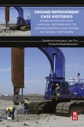
Schlosser (1982) suggested a two-zone model to access the internal stability of a soil-nailed system. This model has been widely used in limit equilibrium analysis in soil-nailing design, as shown in Fig. 20.1. The model separates the soil-nailed system into two zones by a potential failure surface, namely the active zone and the passive zone (or resistant zone). The active zone is the region in front of the potential failure surface, where it has a tendency to detach from the soil-nailed system and pull out the reinforcements. The passive zone is the region behind the potential failure surface, where the area remains more or less stable and prevents the sliding of the system. The soil nails act to tie (or fasten) the active zone to the passive zone. As shown in Fig. 20.1, when the slope slides, the soil nail is not only subject to tensile forces, but also shear forces and bending moments. All these loads originate as reactions to the slope movement before and during the slope failure. To date, the prevailing opinion is that soil nails work predominantly in tension, but stresses are also mobilized due to shear and bending at the intersection of the slip surface with the soil nails (Juran, 1985; Jewell and Pedley, 1990, 1992; Bridle and Davies, 1997). Under service load conditions, the contribution of shear/bending is considered negligible (Jewell and Pedley, 1992; FHWA, 2003).
Small displacements in a soil-nailed system will result in forces being mobilized in the soil nails. The major force is axial tension, with bending moments and shear forces being of secondary importance. The tensile forces in the soil nail vary from the passive zone to the facing (or nail head): starting as zero at the end of the nail, increasing to a maximum value in the intermediate length, and decreasing to a value at the facing (or nail head). Figure 20.1 shows a schematic distribution of tensile forces in the soil nails. The locus of maximum tensile forces of soil nails and the potential failure surface of a slope are also shown in the figure. FHWA (2003) concluded that the point of maximum tension in a soil nail is close to, but does not necessarily occur at, the point of maximum soil shear strain (i.e., the failure surface of a slope).
As previously indicated, the interaction between the soil nail and surrounding soil is complex. Thus, the axial forces are mobilized progressively along the entire soil nail with a certain distribution affected by numerous factors. Clouterre (1991) reported the effect of soil nail inclination on the tensile force distribution in a soil nail Juran (1985) analyzed the effect of the soil nail bending stiffness on the locus of maximum tensile force.
20.2.2 Grouted soil nails
Soil nails are divided into several types, based on the installation methods used. They include driven nails, grouted nails, and jet-grouted nails. Driven nails are composed of ordinary steel bars or angle bars, driven into the ground at the designed inclination by the ballistic method using a compressed air launcher, by the percussive method using hammering equipment, or by the vibratory method using a vibrator. The nail diameter is normally 15–46 mm. Grouted nails typically consist of a steel bar with a diameter 15–46 mm, with 30–80 mm thick grout cover. The steel bar is placed in a predrilled hole (100–150 mm in diameter) with a vertical and horizontal spacing that typically varies from 1 to 3 m, depending on the type of in situ soil. The nails are usually cement-grouted under gravity or low pressure. Various drilling techniques (e.g., rotary, rotary percussive, and down-the-hole hammer) are available to suit different ground conditions. The action of grouting leads to greatly enhanced pullout resistance because of the increased surface area and roughness. The presence of grout also provides the steel bar with increased corrosion protection. Jet-grouted nails are composite inclusions made of a grouted soil with a central steel rod, which can be as thick as 30–40 cm. The main difference between the grouted nails and jet-grouted nails is the grouting pressure and the installation technique. Instead of predrilling the hole and then grouting, the jet-grouting technique uses percussion driving with simultaneous high-pressure grouting (Louis, 1986). The grouting pressure can be greater than 20 MPa, which will cause hydraulic fracturing and recompaction of the surrounding soil and, thus, increase the pullout resistance of the soil nail.
This chapter focuses on grouted soil nails. According to Geoguide 7 (GEO, 2008), a soil-nailed system with grouted soil nails comprises six basic elements:
• Soil-nail reinforcement (typically a steel bar)
• Reinforcement connector (coupler)
• Cement grout sleeve (typically, cement grout made of Portland cement and water at a ratio of 0.42)
• Corrosion protection measures
• Soil nail head
• Slope facing
The advantage of grouted soil nails is that they can overcome underground obstructions (e.g., corestones and drilling spoils) and can provide information about the ground. In addition, long soil nails can be installed using the drilled and grouted method. The size and alignment of the drill holes can be checked before the insertion of reinforcement. The action of grouting leads to the advantage of greatly enhanced pullout resistance because of the increased surface area and roughness. The presence of grout may also provide increased corrosion protection. However, the construction process may also cause disturbance to the ground, and casing is required in some soil conditions to prevent hole collapse during drilling.
20.2.3 Design methods and determination of pullout resistance
There are several different methods currently used for soil nail system design. Most methods are derived from classical slope stability analysis methods with the consideration of additional resisting forces provided by soil nails. Both of the external and internal failures are checked in the design.
The most commonly used design methods include the German method (Gässler, 1987; Stocker et al., 1979), the French method (Clouterre, 1991), the modified Davis method (Bang et al., 1980), FHWA design method (FHWA, 1996, 2003), and the U.K. method (HA68/94, 1994), as well as design methods used in Hong Kong (GEO, 2006,2008). The main differences of these methods are the assumed failure surface, as shown in Table 20.1, and the determination of ultimate soil nail pullout resistance, discussed in the preceding subsection. For the internal stability checks, the French method considers the tensile resistance as well as the shear resistance of the soil nail in the analysis, while the other methods use only the tensile force in the inclusion for design.
Table 20.1
Comparison of different soil nailing design approaches
| Design method | Failure surface | Nail forces |
| German (Gässler, 1987; Stocker et al., 1991) | Bilinear | Tension |
| French (Clouterre 1991) | Circular | Tension, shearing/bending |
| Modified Davis (Bang et al., 1980) | Parabola | Tension |
| FHWA (FHWA, 1996) | Bilinear, circular | Tension |
| U.K. (HA68/94, 1994) | Bilinear | Tension |
| Hong Kong (GEO, 2006) | Any shape | Tension |
The soil nailing design method in Hong Kong is based on a limit equilibrium approach (Powell and Watkins, 1990), where only the contribution of tensile (pullout) resistance of the nail reinforcement in the passive zone is considered. The requirements for the analytical design for soil nailing are given in GEO Technical Guidance Note No. 23 (GEO, 2006). Prescriptive design (Wong and Pang, 1996) for soil nailing has also been promoted in Hong Kong. The technical guidance on the design of soil nail heads for soil cut slopes are given in GEO (2007). The Geoguide 7 (GEO, 2008) provides a recommended standard of good practice for the design, construction, monitoring, and maintenance of soil-nailed systems for Hong Kong. The guide summarizes the experience gained from the use of the soil-nailing technique and the findings of related technical development work.
Yeo and Leung (2001) compared and evaluated different design methods. They found that all the design methods yielded reasonable results, and in general, the U.S., U.K., and Hong Kong methods gave similar soil nail length per meter width slope. However, the Davis method and the German method gave a lower value of 10% and 50%, respectively.
At present, the design methods of the determination of pullout resistance include effective stress method (Hong Kong and U.K.), empirical correlation with SPT-N values (Japan), correlation with pressuremeter tests (France), and correlation with soil types (U.S.A.). Some influencing factors are not well qualified in the current design methods. For example, the effective stress method, adopted in Hong Kong, does not account for factors including soil arching, soil dilatancy, soil saturation condition, roughness of drill-hole surface, and grouting pressure. Pun and Shiu (2007) compared hundreds of pullout test results with the estimated pullout resistance. They found that the actual pullout resistance is generally several times higher than that estimated using the Hong Kong design method (i.e., effective stress method).
20.3 Laboratory pullout testing on grouted soil nails
Laboratory pullout testing is an effective way to study the soil nail pullout behavior under different controlled conditions. Tei (1993) carried out a series of soil nail pullout tests in three types of sands using a 254 mm long, 153 mm wide, and 202 mm high pullout box. Franzén (1998) studied soil nail pullout resistance using a 2 m × 4 m × 1.5 m pullout box for four types of jacked or driven nails under four different stress levels. In Hong Kong, a number of laboratory soil nail pullout tests have been performed at The University of Hong Kong and The Hong Kong Polytechnic University. Pradhan (2003) and Junaideen et al. (2004) reported pullout tests in loose completely decomposed granite (CDG) fill using a sand tank of size of 2 m in length, 1.6 m in width, and 1.4 m in height. Chu (2003) carried out a series of pullout tests using a 0.6 m × 0.6 m × 0.7 m steel box in dense CDG soil. Yin and Su (2006) designed an innovative pullout box. Based on this fully instrumented pullout box, a series of laboratory pullout tests on grouted soil nails have been carried out to investigate the soil nail pullout behavior under controlled overburden pressures, saturation conditions, and grouting pressures (Su, 2006; Zhou, 2008). In the following, first the main features of the pullout box are briefly described. Second, the material properties of the CDG soil and cement grout are presented. Third, the test procedures are described in detail. Finally, the main findings obtained from the laboratory pullout tests regarding the effects of overburden pressure, soil dilation, degree of saturation, and grouting pressure are discussed.
20.3.1 Main features of the pullout box
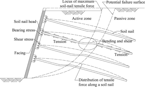
Yin and Su (2006) designed an innovative laboratory pullout box. The design concept of the soil nail pullout box is to enable the study in the laboratory of a short length of soil nail in the passive zone of a soil-nailed slope, as shown in Fig. 20.2. Different overburden pressures can be applied on the top of the pullout box to establish different earth pressure conditions for the soil nails at different depths. The pullout box is instrumented to monitor earth pressure variations and pore water pressure/suction variations in the soil, strains, pullout displacement, and force in the soil nail during the testing.

The internal dimensions of the box are 1000 mm long, 600 mm wide, and 830 mm high, as shown in Fig. 20.3. This pullout box has a few special components for special purposes, as follows:
• An overburden pressure application device is in the top cover of the box, while a rubber bag underneath the top cover is filled with deaired water. The application of water pressure to the top surface of the soil can be controlled in the box. This pressure (up to 400 kPa) is to simulate the overburden pressure in a soil slope.
• An extension chamber on the left side (Fig. 20.3(a)) of the box covers the end of the soil nail, so that no cavity is formed inside the box during the soil nail pullout and the soil stresses on the soil nail inside the box are kept uniform in the longitudinal direction.
• A special pressure chamber (e.g., a triaxial cell) covers the nail head, which works as a waterproof front cover for application of back water pressure for soil saturation.
• A pressure grouting device is used to conduct grouting under a controlled pressure when constructing a soil nail in a drill hole in the box.
• A pullout device with a special reaction frame is used to apply a pullout force at the nail head at a controlled pullout rate.
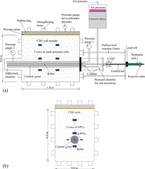
In addition, the pullout box is instrumented with six earth pressure cells, four pore water pressure transducers, one automatic volumemeter, two linear variation displacement transducers (LVDTs), one load cell, one water pressure gauge, and two grouting pressure gauges (one at the nail head and one at the nail end), as shown in Fig. 20.3. Figure 20.4 presents the transducers used in the pullout tests: earth pressure cell, pore water pressure transducer, tensiometer, automatic volumemeter, LVDTs, strain gauge, and load cell connected to a hydraulic jack. More details on the box design and setup can be found in the work of Yin and Su (2006) and Yin et al. (2008).

20.3.2 Material properties of the completely decomposed granite soil and cement grout
The soil used in the series of tests was a completely decomposed granite (CDG) soil, which is a typical in situ soil in Hong Kong. It was taken from a highway construction site at Tai Wai, Hong Kong. A series of basic property tests including particle size distribution, compaction test, specific gravity, liquid, and plastic limit tests were carried out. The procedures as described in BS 1377-2 (1990) were followed.
The particle size distribution of the soil was determined by wet sieving and hydrometer tests following the procedures in BS 1377-2 (1990) and GEO REPORT No. 36 (Chen, 1992). The results of the particle size distribution are shown in Fig. 20.5. It was noted by Su (2006) that the particle size distribution of the CDG soil changed after 24 pullout tests. Results of the original soil and after 24 pullout tests are shown together in Fig. 20.5. As can be seen, the percentage of clay, silt, and sand significantly increased, resulting from the time-to-time compaction in the pullout tests. However, according to USCS, the soil can be classified as SC, clayey sand, both before and after the pullout tests.
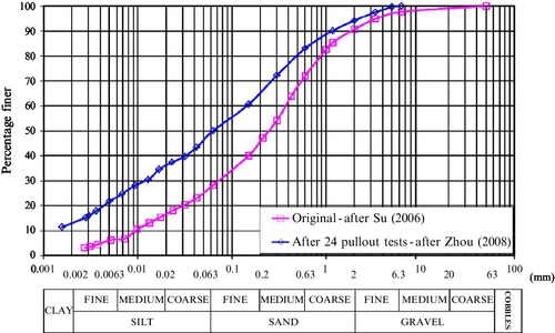
According to British Standards (BS 5930:1999, 1999), the sample soil after 24 pullout tests is composed of 5.8% gravel, 44.1% sand, 36.8% silt, and 13.3% clay. The average diameter of the soil (D50) is 0.063 mm. The coefficient of uniformity (UC) and coefficient of curvature (CC) of the soil are 112 and 0.63, respectively. The plastic limit (PL) and liquid limit (LL) of the soil are 22.7% and 32.8%, respectively. The soil plasticity index (PI) is 10.1%.
A standard compaction test using a 2.5 kg rammer and a container of 1000 cm3 was carried out. The obtained maximum dry density (ρd max) of the soil is 1.802 Mg/m3 with the optimum moisture content mopt of 15.5%. The specific gravity Gs of the soil is 2.645.
Conventional consolidated drained (CD) triaxial tests on recompacted saturated soil specimens and double cell triaxial tests on recompacted unsaturated soil specimens had been carried out. The double cell triaxial test was carried out using an inner cell and an outer cell with the soil specimen within the inner cell. This apparatus makes it possible to measure the volume change of partially saturated soil specimens by measuring the volume change of water inside the inner cell (Yin, 2003). The recompacted soil specimens were taken from the testing soil sample, which was compacted in the box to 95% of the maximum dry density. The measured shear strength parameters from both conventional and double cell triaxial tests are summarized in Table 20.2.
Table 20.2
Shear strength parameters of recompacted CDG soil from CD tests
| Soil type | Degree of saturation (%) | Shear strength | |
| (Sr) | Cohesion (c or c′) | Friction angle (φ or φ′) | |
| Unsaturated | 38 | c = 36.6 kPa | φ = 35.9° |
| 50 | c = 59.5 kPa | φ = 30.4° | |
| 75 | c = 26.8 kPa | φ = 33.8° | |
| Saturated | 98 | c′ = 0 kPa | φ′ = 35.0° |

For cement grout, uniaxial compressive strength (UCS) tests were carried out by Su (2006) on both cylindrical and cubic specimens. The average uniaxial compressive strength σc of the cement grout on the cylindrical specimens was 32.09 MPa. The average compressive strength from four cubic specimens was 32.2 MPa. The density of the cement grout was 1.886 Mg/m3.
20.3.3 Test procedures
Test procedures include test preparation, soil compaction, application of the overburden pressure, hole drilling and preparation of the steel rebar, grouting with pressure, saturation with back pressure, pullout of the soil nail, and post-test examination after the test. The procedures of saturation and application of pressure grouting are the two most difficult and important steps during the testing. Su (2006) carried out a total of 24 tests, most tests of which were on unsaturated soil and four tests were conducted with grouting pressures. In Zhou (2008), pullout tests on saturated soil under different grouting pressures were conducted smoothly with the experience gained from Su (2006), together with some improved devices and measurements. For instance, the device for pressure grouting was improved for applying larger grouting pressures. Fiber optical sensors were used together with the strain gauges to measure the strains along the soil nail. The following describes in detail the test procedures of the laboratory pullout tests on grouted soil nails. Note that for the tests on zero grouting pressure condition or unsaturated soil, the procedures of pressure grouting and saturation shall be skipped.
Test preparation
The inner surface of the box was lined with a smooth stainless steel sheet. Before the test, a flexible plastic film was used to cover the inner surfaces of the box, as shown in Fig. 20.6(a). Lubricating oil was spread between the film and the box surface. The interface direct shear tests (Su, 2006) showed that the friction between the flexible plastic film and the inside surface of the box was only 6.9°. Such small friction enabled the plastic film to move with the soil in the vertical direction during the testing. Side friction of the box was thus dramatically reduced. After placing the flexible plastic film, the drilling machine was placed and fixed on the ground (Fig. 20.6(b)). The drilling rods were then connected to the drilling machine to predefine the position and direction of the drill hole, as shown in Fig. 20.6(c,d).

Soil compaction
The CDG soil was compacted in layers (65–105 mm in thickness for each layer) to a dry density of 95% of the maximum dry density (ρd max = 1.802 Mg/m3), that is, ![]() 1.712 Mg/m3. The soil mass amount for each layer was weighed before being placed into the box, to achieve the required dry density. For the pullout tests on saturated condition, the initial moisture content of the soil was around 16%, which was close to the optimal moisture content (mopt) of the CDG soil. For the tests on unsaturated condition, the initial moisture content of the soil was prepared at the desired water content.
1.712 Mg/m3. The soil mass amount for each layer was weighed before being placed into the box, to achieve the required dry density. For the pullout tests on saturated condition, the initial moisture content of the soil was around 16%, which was close to the optimal moisture content (mopt) of the CDG soil. For the tests on unsaturated condition, the initial moisture content of the soil was prepared at the desired water content.
During compaction, a total of six earth pressure cells were imbedded in the soil in three layers. Each pressure cell was installed in four steps. First, a small pit in the compacted soil was made in which to place the pressure cell, followed by a slot in which to place the wire. Second, a layer of fine soil was put into both the pit and slot. Third, the pressure cell and its wire were placed into the pit and slot and the cell’s position was adjusted using a leveler. Finally, a second layer of fine soil was used to cover the pressure cell and the wire.
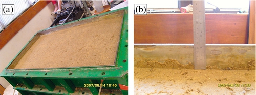
After the last layer of soil was compacted into the box, a thin wooden plate (30 mm in thickness) was placed on the top surface of the soil. This plate was semiflexible and helped to make the applied overburden pressure on the soil surface more uniform. It is noted that if this plate was not used, after applying the overburden pressure on the soil surface, the rubber bag underneath the top cover would be in good contact with the soil surface in the central area, but not at the internal boundaries of the box wall. That is to say, the soil settlement would be not uniform during the testing without the use of the wooden plate. Figure 20.7(a) shows the soil surface after a test. It is seen that the settlement at the soil surface is quite uniform. It is also observed from Fig. 20.7(b), that the flexible film settles together with the soil during the test.
Application of overburden pressure
After placing the wooden plate, the top cover was fixed and the rubber bag was filled with deaired water. The water pressure in the rubber bag was then increased to a certain value to simulate the overburden soil pressure in a soil slope. The overburden pressure was then adjusted and maintained to a certain value when the soil settlement became stable. After application of the overburden pressure, the volume change of the water inside the rubber bag was monitored using a volumemeter, and thus the average soil settlement at the top surface can be calculated.
Hole drilling and preparation of the steel rebar
When soil settlement stabilized, a horizontal hole of 100 mm in diameter was drilled using a lab-size drilling machine. Because the drilling position and direction were adjusted before the soil compaction, the drilled hole can be controlled around the desired position. Figure 20.8 shows the procedure of the drilling and a drilled hole. The hole was drilled through the box (1 m in length) and into the additional cylinder 20 mm.


After drilling, a high yield ribbed steel bar was placed in the middle of the drill hole. The diameter of the steel rebar was 40 mm, which is commonly used in Hong Kong soil-nailing practice. Two methods have been used to measure the strain changes along the soil nail: electrical resistance-type strain gauges (SG) and fiber Bragg grating (FBG) sensors. The FBG-based monitoring system developed by Zhu et al. (2007) was used in the present study for the soil nail strain monitoring. Before insertion of the steel bar, 4 strain gauges and a series of FBG sensors were attached on the bar surface, as shown in Fig. 20.9(a,b). The FBG sensors were installed beside the locations of strain gauges to compare and verify the results of the strain gauges during testing. The FBG sensors were temperature compensated by a reference sensor and multiplexed in serials to form a quasidistributed sensing array. The locations of the strain gauges and FBG sensors are shown in Fig. 20.10.


The front cover of the drilling hole as shown in Figs. 20.9(c,d) was specially designed for pressure grouting. There are four holes for the outlet of the steel bar, two grouting pipes (one for the ingoing cement slurry and the other for the outgoing grouting), and the wires of the strain gauges and fiber optical sensors. All the holes were sealed with O-rings, as shown in Fig. 20.9(d), to complete the pressure grouting. A sealed O-ring is also used at the front cover, as shown in Fig. 20.9(c). A view of a whole prepared the steel bar is shown in Fig. 20.9(e).
Pressure grouting
Cement slurry grouting was carried out after the hole was open for about 13 hours. For pressure grouting, it is important to make sure the drill hole is sufficiently sealed. This was completed as follows:
1. The prepared steel bar was carefully inserted bar into the hole (Fig.20.11(a)) and its position adjusted to the center of the hole.
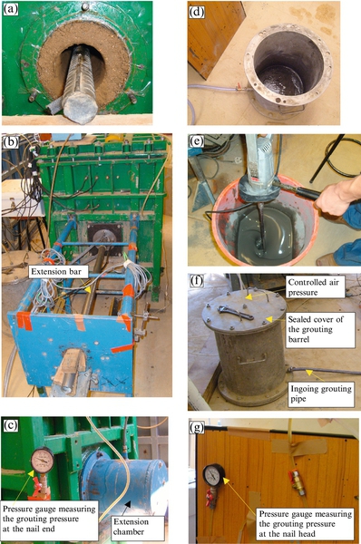
2. The front cover to the pullout box was fixed (Fig. 20.11(b)) and an extension bar to the rebar head was connected to sustain the rebar at the center of the hole.
3. The extension chamber to the back of the box was fixed (Fig. 20.11(c)) and the pressure gauge, which was used to monitor the grouting pressure during the grouting, was connected to the extension chamber.
4. The grouting barrel was connected to the ingoing grouting pipe (Fig. 20.11(d)).
5. The cement slurry was prepared with a water-cement ratio of 0.42 (Fig. 20.11(e)). The slurry was stirred for 15 mins to get a good mixture and then it was transferred into the grouting barrel.
6. The hole was filled with cement slurry in a few minutes. It was done by applying a low pressure of about 20 kPa to the sealed grouting barrel, as shown in Fig. 20.11(f). The air in the hole was exhausted from the outgoing grouting pipe while filling the hole with cement slurry from the ingoing grouting pipe.
7. The outgoing pipe was connected to another pressure gauge at the front of the box at the moment cement slurry was exhaled out (Fig. 20.11(g)). Then the grouting pressure was increased to a required value and kept for about 30 mins until the initial setting of the cement slurry had almost finished. It was observed that the grouting pressure measured by the two pressure gauges (one at the nail head and the other at the nail end) were almost the same during the grouting, and the pressure dropped quickly within about 8–15 minutes after the grouting pressure had applied. After about 2 hours, the pressure gauges were removed when the cement slurry had been hardened and lost its fluidity.
Saturation
Two days after the pressure grouting when the cement grout had gained a certain value of strength, the soil in the box was saturated by back pressure method. The procedures are described in more detail in the following.
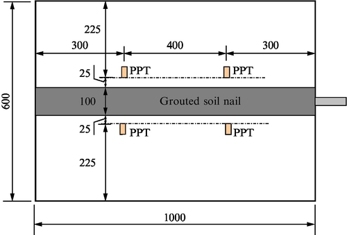
• A total of four pore water pressure transducers (PPT) were installed in the soil near to the soil nail. The locations of the PPTs are shown in Fig. 20.12. All the outlets of the wires of earth pressure cells and pore water pressure cells were sealed before the saturation.
• The soil in the extension chamber was removed and then fixed back to the box. Later on, the extension chamber would be filled with water for the soil saturation (Fig. 20.13(a)).

• The front cover, which was used to block the hole during the pressure grouting, was removed and the waterproof triaxial cell (shown in Fig. 20.13(b)) set up for the soil saturation. The waterproof triaxial cell has two functions: to apply water (back) pressure from the soil nail head for the soil saturation and to allow the steel guide bar to move smoothly along the center of the cell with the applied water (back) pressure so that the pullout can be conducted without any leakage.
• Plastic tubes were connected to the six holes in the side plates and near the bottom of the box, the extension chamber at the back, and the waterproof cell at the front, so that water could flow into the soil through these tubes.
• A vacuum air pump was used to pump out the air from the soil through the four holes in the side plates and near the top of the box. Under the suction pressure (less than 100 kPa), water filled the extension chamber and the waterproof front cell, and also flowed into the soil.
• When the extension chamber and the waterproof front cell were almost filled with water, a back water pressure of about 30 kPa was applied and maintained. The increase in the pore water pressure in the soil was monitored and recorded by the four pore water pressure cells. The overburden pressure was then increased by 30 kPa to maintain the effective overburden pressure consistent in the soil, as shown in Fig. 20.13(c).
Pullout of the soil nail
Five days after grouting when the cement grout strength was about 32 MPa, the cement grouted soil nail was pulled out from the nail head using a hydraulic jack against a steel reaction frame. The load was applied step by step and was held for 1 hour for each loading step. The increment for each loading step was about 5 kN. After reaching the peak pullout resistance, the nail was continuously pulled out to 100 mm at a rate of about 1.2 mm/min.
The total length of the soil nail was 1.2 m with 0.2 m inside the extension chamber at the back of the pullout box. As mentioned in the previous procedure, the soil in the extension chamber was removed two days after the grouting. During the pullout testing, when the nail head was pulled out for 100 mm, the additional length (200 mm) in the extension chamber moved into the box for 100 mm, so that the soil nail length inside the box was retained as 1.0 m in full contact with the soil in the box.
During the soil nail pullout, the variations of the pullout force, pullout displacement, vertical earth pressures at six locations, pore water pressures at four locations, and the strains in the soil nail were automatically monitored and recorded.
Post-test examination
After the soil nail was pulled out of 100 mm displacement, the overburden pressure and the water back pressure were released and the computer stopped monitoring and recording data from transducers. The entire soil nail was then fully extracted from the drill hole for visual inspection. The diameter of the front, middle, and end parts of the grout column and the attached soil were measured. The soil near the nail surface was collected to measure the water content immediately after the test. The soil in the box was then removed. During the removal of the soil, the water content of the soil in each layer was measured to check the soil saturation degree. The locations of the earth pressure cells in the soil were also measured after the test, as these locations may change due to the soil settlement during the test.
Test program
A series of laboratory pullout tests were carried out by Su (2006) Thirty tests were performed under different combinations of overburden pressure (OP = 40 kPa, 80 kPa, 120 kPa, 200 kPa, 240 kPa, 300 kPa, 350 kPa), grouting pressure (GP = 0, 80 kPa, 130 kPa, 250 kPa, and 300 kPa), and degree of saturation (Sr = 38%, 50%, 75%, and 98%). Some tests failed or results were very good. Table 20.3 summarizes 30 tests in the program.
Table 20.3
Test program for the laboratory soil-nail pullout tests under four OP and four GP in nearly saturated soil conditions
| No. | GP (kPa) | Sr (%) | OP (kPa) | No. | GP (kPa) | Sr (%) | OP (kPa) |
| 1 | 0 | 38 | 40 | 16 | 0 | 98 | 200 |
| 2 | 0 | 38 | 120 | 17 | 0 | 98 | 300 |
| 3 | 0 | 38 | 200 | 18 | 80 | 50 | 80 |
| 4 | 0 | 38 | 300 | 19 | 80 | 50 | 200 |
| 5 | 0 | 50 | 80 | 20 | 130 | 50 | 80 |
| 6 | 0 | 50 | 120 | 21 | 130 | 50 | 200 |
| 7 | 0 | 50 | 300 | 22 | 80 | 98 | 80 |
| 8 | 0 | 75 | 40 | 23 | 80 | 98 | 350 |
| 9 | 0 | 75 | 80 | 24 | 130 | 98 | 80 |
| 10 | 0 | 75 | 120 | 25 | 130 | 98 | 120 |
| 11 | 0 | 75 | 200 | 26 | 130 | 98 | 240 |
| 12 | 0 | 75 | 300 | 27 | 250 | 98 | 120 |
| 13 | 0 | 98 | 40 | 28 | 250 | 98 | 240 |
| 14 | 0 | 98 | 80 | 29 | 250 | 98 | 350 |
| 15 | 0 | 98 | 120 | 30 | 300 | 98 | 350 |

In the following sections, the effects of different influencing factors on the soil nail pullout resistance are discussed using an average peak pullout shear stress (![]() ), which is calculated from the measured peak pullout force at nail head divided by the active surface area of the nail,
), which is calculated from the measured peak pullout force at nail head divided by the active surface area of the nail,
where P is the pullout force measured from the load cell, D is the average diameter of the soil nail measured after pullout of the soil nail, and L is the length of the soil nail in contact with the soil inside the box, which is retained as L = 1.0 m in full contact with the soil in the box.
20.4 Effect of overburden pressure
The stress conditions that will influence the pullout resistance of a soil nail are normally referred to as the normal stresses acting on the nail surface. Current views on how the overburden pressure influences the normal stress acting on the nail surface are diversified. Some researchers believe that the normal stress is related to the soil overburden pressure corresponding to the depth of soil, such as Jewell (1990). Some other researchers hold the view that the normal stress is independent of soil depth, such as Schlosser and Guilloux (1981) and Cartier and Gigan (1983).
Su (2006) and Su et al. (2008) presented results of the pullout tests in the soil at 38%, 50%, 75%, and 98% (submerged) degrees of saturation and under applied overburden pressures of 40 kPa, 80 kPa, 120 kPa, 200 kPa, and 300 kPa. The grouting pressure was not applied in these tests. It was found that: (1) after drilling the horizontal hole in the soil, most of the soil stresses around the hole were released and the stress recovery was minimal after grouting; (2) during pullout, the normal stress in the soil surrounding the soil nail was increased owing to the constrained dilatancy of the surrounding soil; (3) most of the pullout shear stress-displacement curves exhibit a peak and postpeak displacement softening behavior, in particular for tests in soil at higher degrees of saturation; and (4) the development of pullout shear resistance was mainly attributed to the constrained dilatancy of the surrounding soil.
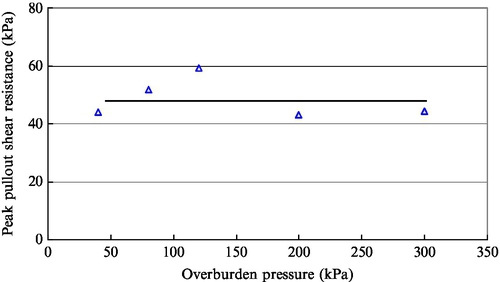
The peak shear resistances under different applied overburden pressures and different degree of saturation are analyzed for comparison. It can be seen in Fig. 20.14, for tests in soil at degree of saturation of 38%, the peak pullout shear resistances were quite constant under different overburden pressures. For tests under submerged condition as shown in Fig. 20.15, the peak pullout shear resistances were also generally constant. It is also found that for the tests under submerged conditions, the submerge procedure reduced the influence of drilling disturbance so that the results were generally constant. The test results suggest that there was no apparent relationship between the pullout shear resistance and the applied overburden pressure, which was consistent with the observations from Cartier and Gigan (1983) and Clouterre (1991) by field pullout tests.
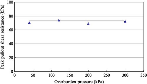
The pullout resistances under lower overburden pressure could be larger than those under higher overburden pressure. The variation of the peak pullout shear resistance under different overburden pressures might have been caused by some disturbance factors, such as misalignment of the pullout force, variations in stress condition of the soil and roughness of the nail surface along the nail, disturbance to the hole surface due to drilling, and so on.
20.5 Effect of degree of saturation
Among a number of factors influencing the pullout resistance of grouted soil nails, the degree of saturation of soil is an important influencing factor, especially for permanent soil-nailed structures. This is because the degree of saturation of the soil mass changes frequently due to the variation of groundwater table and weather conditions. The degree of saturation of the soil can alter the suction of the soil. The pullout resistance of a soil nail may drop to an unsafe level in intense rainfalls due to the increase of the degree of saturation. Only a few researchers have investigated the influence of degree of saturation of soil on the pullout resistance of soil nails. In the French National Research Project Clouterre (1991), the maximum pullout force was found to be reduced by more than a half when the moisture content was increased from the optimum water content to the saturation moisture content. Pradhan (2003) noted from laboratory pullout tests with cement grouted nails in loose CDG fill at both natural moisture content and nearly saturated conditions that only the nail–soil interface adhesion was reduced due to high degree of saturation but the interface friction angle remained unchanged.
The pullout box (Yin and Su, 2006) is waterproof and allows application of back pressure to speed up the saturation process of the testing soil. A series of pullout tests on grouted soil nails were carried out at degrees of saturation from 38% to nearly saturated conditions (Su, 2006; Su et al., 2007; Zhou, 2008). Soil samples taken after testing revealed that a high degree of saturation (~ 98%) was achieved. Su et al. (2007) discussed the influence of degree of saturation on the soil nail pullout behavior. It was found that (1) the migration of shearing plane from the interface between the nail surface and the surrounding soil to the interior of the soil was observed with the increase of degree of saturation of the soil; (2) the displacement at peak pullout shear resistance for saturated tests was smaller than those for partially saturated tests, and the decreasing rates of the postpeak pullout shear stress increased with the increase in degree of saturation of the soil; (3) the peak pullout shear resistance varies with different degrees of saturation of the soil, with higher resistances at the degrees of saturation of 50% and 75%; and (4) the increase in earth pressure at peak pullout resistance for submerged tests was much smaller than that in tests at other degrees of saturation. This indicates that the soil dilatancy was reduced when the soil was saturated and as a result the pullout resistance decreased.
Figure 20.16 shows the relationship between the peak pullout shear resistance and degree of saturation of soil under different overburden pressures of (a) 40 kPa, (b) 120 kPa, (c) 200 kPa, and (d) 300 kPa. From the plotted trend lines in the figures, it can be observed that the peak pullout shear strength first increased and then decreased with increase in degree of saturation of the soil. It is believed that if the soil is dry, water is more readily absorbed by the soil with higher suction. This may cause more contraction of the cement grout thus reducing the bond strength between the nail surface and the surrounding soil. In the tests with soil at 38% degree of saturation, further decrease of earth pressure was observed immediately after grouting and the earth pressure did not recover after the cement grout had hardened. This is a possible indication of the contraction of the cement grout.

The actual reason is unknown and needs to be found out by further tests and analyses. In this respect, tests conducted using the pressure grouting method to improve the contact between the nail surface and the surrounding soil may throw some light onto it. As in the submerged tests, the decrease of soil cohesion could be one of the reasons for the decrease of pullout resistance. The decrease of dilatancy of the soil could be another reason. It was observed from the earth pressure responses during pullout that the increase in earth pressure at peak pullout resistance for submerged tests was much smaller than that in tests in the soil at dryer conditions.
It can be seen from Fig. 20.16 that the peak pullout shear strength for tests at a degree of saturation of 75% was about two times that for saturated tests. Some of the tests in soil at 50% degree of saturation were even higher. This indicates that the effect of degree of saturation on soil nail pullout resistance is significant and should be carefully addressed in the design of a soil-nailing system.
20.6 Effect of pressure grouting in unsaturated condition
In Hong Kong, soil nails are generally grouted under gravity. During the injection, cement slurry (usually prepared at some distance away from the drill holes) is normally transferred through pipes into the drill holes by an applied pumping pressure. The applied pumping pressure depends on the field conditions, such as the distance and height between cement slurry and the drill holes. The grouting pressure in the drill holes is not controlled during grouting, as long as the cement slurry flows into the holes smoothly. After the hole is full, the pumping pressure is released and the hole sealed. The soil nails are normally installed with a downward inclination of 20°. Therefore, grouting pressure may exist during grouting owing to the pumping pressure, and be further maintained at certain level by gravity effect.
Studies on the significance of the pressure grouting are common for anchors, piles, and ground improvement, but limited for soil nails. Soga et al. (2005) presented results of a laboratory investigation of multiple grout injection into clay. Juran and Elias (1990) reported that for cohesionless soils, grouting pressures of 350–700 kPa were commonly used to prevent caving as the casing would be withdrawn. The degree to which the grouting pressure influences the soil nail pullout resistance is of interest to engineers and researchers. Yeung et al. (2005) carried out field pullout tests on glass fiber reinforced polymer (GFRP) pipe nails with cement pressure grouting in a CDG soil slope in Hong Kong and observed a significant increase in the pullout resistance due to the pressure grouting. Su (2006) and Yin et al. (2008) reported data from a limited number of laboratory pullout tests and discussed the influence of cement pressure grouting on the soil nail pullout resistances. From the limited number of pullout tests, the soil was unsaturated soil with a degree of saturation of 50% and the applied grouting pressures were 80 kPa and 130 kPa (Yin et al., 2008). The following was found from the test results:
• The grouting pressure inside the hole increased quickly, but then dropped rapidly due to hardening of the cement grout and shrinkage of grout volume because of water seepage from the cement grout to the surrounding soil (accompanied by dissipation of the excess water pressure inside the grout and absorbing of water in the grout by the dryer surrounding soil).
• At peak pullout resistance, the earth pressures measured by earth pressure cells close to the nail for pressure grouting tests increased to much higher values than those for gravity grouting tests. For most of the tests, the earth pressure at peak pullout resistance was even higher than the applied overburden pressure. This is probably because the contact between the soil nail surface and the surrounding soil was improved by the grouting pressure so that the effect of the constrained dilation of soil was strengthened.
• The amount of soil adhered to the nail surface after pullout increased with the increase in grouting pressure.
• The average peak pullout shear resistance of the soil nail increased almost linearly with the increase in grouting pressure.
Figure 20.17 shows peak pullout resistance versus grouting pressure under the overburden pressures OP = 80 kPa and 200 kPa. For the test nail prepared under a grouting pressure of 80 kPa, the peak pullout shear strengths for the two overburden pressures were nearly the same. However, for the one prepared under a higher grouting pressure of 130 kPa, the pullout shear strengths for OP = 200 kPa was substantially higher than that for OP = 80 kPa. This illustrates that the peak pullout shear resistance of the nail was less dependent on the overburden pressure when the grouting pressure was low, but the peak pullout resistance increased with increasing overburden pressure when the grouting pressure was high.

The probable explanation is that when the grouting pressure was low, the disturbed soil around the drill hole was still loose and the soil arching effect existed to a certain extent. When the grouting pressure was high, the loosened soil was well compacted by the grout; and as a result, the strength of the soil increased back to or even higher than that before the drilling. This leads to a change in the stress condition in the soil around the hole and the soil arching effect no longer existed. As such, most of the vertical stress above the nail was transferred to the nail surface.
20.7 Effects of overburden and grouting pressure in a saturated condition
Zhou (2008) and Yin and Zhou (2009) analyzed the laboratory pullout test results on grouted soil nails and evaluated the effects of both grouting pressure and overburden pressure on the soil nail pullout behavior in a saturated CDG soil. It has been found that:
• For the soil nail pullout behavior, the peak (or maximum) normal stress does not correspond to the peak pullout resistance, due to the progressive failure nature at the soil–nail interface.
• Smaller dilation was observed at the soil–nail interface in the present pullout tests for soil in a saturated condition, compared to the much larger dilation for a soil nail in unsaturated soil, as reported by others. This is a result of reduction of suction in the soil and the higher stress level at the soil–nail interface after saturation.
• Similar to the case in unsaturated condition, overburden pressure and grouting pressure have interactive influences on soil nail pullout resistance. The soil nail pullout resistance is hardly or slightly dependent on the overburden pressure when the grouting pressure is low, but increases with the overburden pressure when the grouting pressure is higher.
Figure 20.18 shows the effect of overburden pressure on soil nail pullout resistance at different grouting pressures. It can be seen that for GP = 0 kPa and 80 kPa, the peak pullout resistance is hardly dependent on the overburden pressure; for GP = 130 kPa, the peak resistance increases a little when overburden pressure increases from 120–240 kPa; but at GP = 250 kPa, the peak pullout resistance dramatically increases with the overburden pressure. Therefore, it can be concluded that the effect of overburden pressure on the soil nail pullout resistance is small when the grouting pressure level is low (< 80 kPa), the effect emerges when the grouting pressure increases to 130 kPa, and the effect on the increase of soil nail pullout resistance becomes significant when GP = 250 kPa.
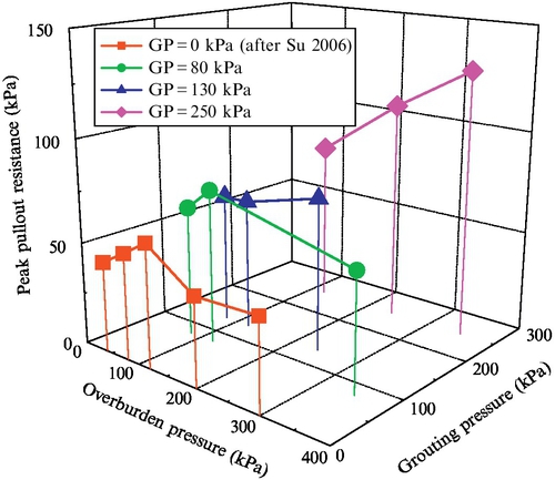
Figure 20.19 shows the effect of grouting pressure on soil nail pullout resistance at different overburden pressures. No distinct influence of the grouting pressure is found on the peak pullout resistances for OP = 80 kPa and 240 kPa. However, when the overburden pressure is higher (i.e., OP = 240 kPa and 350 kPa), a significant increase of peak resistance is observed with the grouting pressure. Therefore, it is concluded that soil nail pullout resistance significantly increases with the grouting pressure when the overburden pressure level is high, such as OP = 240 kPa and 350 kPa.

To account for the interactional effects of overburden pressure and grouting pressure, an empirical equation for pullout resistance has been proposed (Zhou, 2008, Yin and Zhou 2009). In the proposed empirical linear equation, two fitting parameters cG′ and μG′ are introduced. It is found that these two parameters are dependent on the grouting pressure (pG). The relationship between cG′ (or μG′) and pG is nonlinear. The proposed empirical equation may be used to estimate the soil nail pullout resistance (or interface shear resistance) for design purpose for the soil and conditions in this study (or similar soils and conditions).
20.8 Estimation of pullout resistance using the bayesian approach
As discussed in the previous sections, soil nail pullout resistance is influenced by a number of factors, such as the method of installation, normal stress, overburden pressure (OP), degree of saturation (Sr), grouting pressure (GP), and soil properties. Zhang et al. (2009) studied the uncertainties of soil nail pullout resistance with consideration of overburden pressure, grout length, soil suction, and soil dilation. Due to the complexity of the mechanism of soil nail pullout resistance, a general formula considering multiple influencing factors is rare in the literature.
Bayesian inference is very useful for civil engineering applications because there are many types of modeling and parametric uncertainty in civil engineering problems (Yuen, 2010a,b; Yuen and Kuok, 2011). Yan et al. (2009) successfully analyzed the correlation between the compression index and other soil properties and proposed the predictive formula for compression index. Based on the laboratory pullout test results on grouted soil nails, Zhou et al. (2013) performed systematic analysis using Bayesian inference to construct a reliable relationship for pullout resistance of grouted soil nail. To determine the suitable complexity of this formula, Bayesian model class selection in conjunction with multivariate linear regression was adopted in the analysis.
By incorporating the observations of different influencing factors discussed before, the full model class for the estimation of the maximum pullout shear stress (![]() ) is proposed as follows:
) is proposed as follows:
where ![]() is the estimation value of
is the estimation value of ![]() . The contribution from the grouting pressure GP alone is represented by a linear relationship in the first term. The fifth term also includes the effect of GP. For the degree of saturation Sr, a quadratic function is used to represent the relationship between
. The contribution from the grouting pressure GP alone is represented by a linear relationship in the first term. The fifth term also includes the effect of GP. For the degree of saturation Sr, a quadratic function is used to represent the relationship between ![]() and Sr—that is, the second and third terms in Eq. (20.2).
and Sr—that is, the second and third terms in Eq. (20.2).
The effect of OP is considered in the fourth term. Considering the multiply effect of GP and OP on the soil nail pullout resistance under both unsaturated and saturated soil condition, the product of the overburden pressure and grouting pressure: ![]() is taken as the fifth influencing factor candidate to reconfirm from a Bayesian perspective if this observation is significant. Finally, the constant term b6 is used to account for any possible offset.
is taken as the fifth influencing factor candidate to reconfirm from a Bayesian perspective if this observation is significant. Finally, the constant term b6 is used to account for any possible offset.
To propose a reliable (neither overfitted nor underfitted) predictive model class, other model class candidates were constructed based on the model in Eq. (20.2). These model class candidates were generated by including different combinations of terms on the right side of Eq. (20.2) (e.g., ![]() ). There are
). There are ![]() model class candidates to be analyzed by Bayesian method. The selected model class possesses rational balance between data-fitting capability and robustness to measurement noise and modeling error. Bayesian model class selection was performed and the most plausible model class was selected as the proposed design formula for the pullout resistance of soil nails:
model class candidates to be analyzed by Bayesian method. The selected model class possesses rational balance between data-fitting capability and robustness to measurement noise and modeling error. Bayesian model class selection was performed and the most plausible model class was selected as the proposed design formula for the pullout resistance of soil nails:
where ![]() (in kPa) represents the estimation of maximum pullout shear stress. The values of GP and OP are also in kPa. The degree of saturation Sr uses the digital format. For example, if Sr is equal to 50%, 0.5 is used in Eq. (20.3).
(in kPa) represents the estimation of maximum pullout shear stress. The values of GP and OP are also in kPa. The degree of saturation Sr uses the digital format. For example, if Sr is equal to 50%, 0.5 is used in Eq. (20.3).
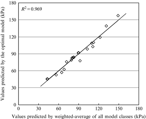
Although it is common to use the most plausible model class as the predictive formula (i.e., Eq. (20.3)), there exists a possible more robust/reliable choice to use all model classes, with the weightings being the posterior plausibility. This multimodel predictive formula uses all model classes to provide the “hyper-robust prediction” instead of using only the most plausible model class (Zhou et al., 2013). To compare the performance of this multimodel formula with the optimal model in Eq. (20.3), their predicted values are compared in Fig. 20.20. The high R2 value (0.969) indicates that the optimal model class (i.e., Eq. (20.2)) is almost as robust as the hyper-robust model for fitting the maximum pullout shear stress. Therefore, it is sufficient to use the model in Eq. (20.3) as the proposed design formula.
By using the Bayesian model class selection approach, the proposed optimal formula, Eq. (20.3) includes three terms only. It possesses rational balance between the data-fitting capability and the robustness to measurement noise and modeling error. It is found that the most important factors in the estimation of soil nail pullout resistance are the degree of saturation and the product of grouting pressure and overburden pressure.
It is found that the maximum pullout shear stress occurs when Sr is 0.57 in this case. This is consistent with the observations in the pullout tests by Su et al. (2007). Furthermore, the significance in correlating with the product of grouting pressure and overburden pressure (Yin and Zhou, 2009) was reconfirmed by the Bayesian model class selection results.
Zhou et al. (2013) also compared the predictions of pullout resistance by Eq. (20.3) and the effective stress method using the laboratory and field pullout test data. It was found that Eq. (20.3) possesses far stronger correlation with the measurements than the effective stress method.
20.9 Conclusion
Laboratory pullout testing is an effective way to study the soil nail pullout behavior under different controlled conditions. The technique and test procedures of laboratory pullout testing of grouted soil nails under controlled overburden pressure, degree of saturation, and grouting pressure are recounted. Based on the series of laboratory pullout tests, the effects of some key factors on the pullout resistance of grouted soil nails have been systematically analyzed. These factors include overburden pressure, degree of saturation, and grouting pressure in both unsaturated and saturated conditions. Finally, a probabilistic estimation of pullout resistance of grouted soil nail is reviewed. By using the Bayesian model class selection approach and all the pullout resistance data from laboratory tests, an optimal formula has been proposed and it possesses rational balance between the data-fitting capability and the robustness to measurement noise and modeling error. It is found that the most important factors in the estimation of soil nail pullout resistance are the degree of saturation and the product of grouting pressure and overburden pressure.