Characteristics of Soft Peats, Organic Soils, and Clays, Colombo–Katunayake Expressway in Sri Lanka
Jeff Hsi; Chanaka Gunasekara; Viet Nguyen SMEC Australia Pty Ltd, Sydney NSW, Australia
Abstract
Colombo–Katunayake Expressway is a major road project in Colombo, Sri Lanka. The project involves construction of a 25.8-km freeway linking the airport and Colombo. The majority of the route traverses flood plain and marshy ground consisting of very soft peats, organic soils, and clays up to 15 m thick. Construction of road embankments over these soils involves risks of embankment instability and excessive settlement. Soft ground treatments adopted to overcome the problems include methods of preloading and surcharging, prefabricated vertical drains, sand compaction piles, and stone columns. Instrumentation and monitoring of the road embankments have also been implemented during construction using settlement plates, settlement stakes, piezometers, observation wells, and inclinometers. Extensive geotechnical investigations, including boreholes, cone penetration tests, vane shear tests, and laboratory soil tests have been carried out to investigate the subsurface profile and soil properties. This information has been collated, compiled, interpreted, and summarized. The field monitoring information has been used in back-analysis to calibrate the geotechnical model that represents actual soil characteristics. This chapter focuses on the properties and characteristics of the soft peats, organic soils, and clays interpreted from the geotechnical investigations and field performance.
Acknowledgments
The authors thank the Road Development Authority of Sri Lanka for permission to publish this chapter. Our thanks also go to all others who assisted in collation of the vast amount of investigation data.
25.1 Introduction
The proposed Colombo–Katunayake Expressway (CKE) is the first major highway in Sri Lanka and connects the International Airport at Katunayake to the capital city of Colombo. The majority of the road traverses marshy and waterlogged areas. The key geotechnical issue associated with the CKE project is construction of road embankments over soft soils, which include peats, organic soils, and clays up to a depth of 15 m.
The following problems associated with the soft soils need to be addressed during design and construction of the road embankment:
• Constructability: Embankment stability during construction
• Long-term performance: Total and differential embankment settlement after construction
To address such problems it is important to understand the characteristics and behavior of the soft soils comprising peats, organic soils, and clays. This is done by utilizing a combination of methods, which include site and laboratory testing with statistical analysis, assessment of field monitoring data, and consideration of published information for similar materials. This chapter describes the work undertaken to assess the characteristics of the soft soils and presents the results of the study.
25.2 Project description
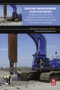
The CKE is a 25.8 km grade-separated dual two-lane expressway traversing north to south over the western coastal floodplains and lagoons of Sri Lanka. The terrain along the proposed expressway predominantly consists of marshy lands, which are mostly waterlogged. The general plan layout of the CKE is shown in Fig. 25.1.
The project area is located immediately north of Colombo on the western coastal platform of Sri Lanka. The proposed alignment starts at the Kelani River and traverses the flood plains of the Kelani River and the marshy areas of Peliyagoda and Muthurajawela before it reaches the Negombo lagoon area. At about chainage 19 + 000, the alignment passes over the lagoon deposits of the Negombo coastal belt and then traverses over high grounds formed of shallow sea deposits before the proposed CKE ends just past the railway crossing at Katunayake.
The first one-third of the road alignment is over very soft peat with a depth up to 12 m, and the combined soft soil depth is up to 15 m. Within this section, the road embankments need to be constructed to a height of up to 8 m. Road embankment construction work commenced in June 2001 but was subsequently suspended in November 2002. As such, the road embankments were constructed to various levels along the length of the alignment with different types of soft ground treatments (SGTs) implemented.
25.3 Site geology
Geomorphologically, the project area can be categorized as a coastal alluvial plain that is composed of overburden alluvial soil deposited on residual soils or highly weathered basement rock. A belt of lateritic high ground bounds the project area on the north and east and recent alluvial deposits in the south.
The geological formations of the area belong to the Wanni Complex of the Vijayan Series of Sri Lanka. The Wanni Complex is characterized by thick sequences of gneisses comprising migmatitic, garnet, and biotite gneisses (Cooray, 1984). These Proterozoic metamorphic rocks belonging to the Precambrian era are overlaid by Quaternary and recent deposits such as sands, silts, clays, organic clays, and peat.
The subsoil sequence in the marsh areas and abandoned paddy areas generally consists of partially decomposed vegetable matter at the top, followed by a layer of peat and organic clay. The peat and organic clay layers are underlain by alluvial silty sandy strata. Occasionally, the organic clay layer transforms through sandy clay and clayey sand into sand. At some locations, a lens of partially decomposed vegetable matter is observed within the alluvial silty sandy strata. The depositional soil layers overlie a comparatively thin residual soil layer that overlies highly weathered basement rock. Figure 25.2 shows the interpreted subsurface conditions encountered along the CKE alignment based on the borehole information.

Genetically, the whole subsurface overburden profile could be considered as a result of minor oscillations of the sea levels and flooding of the low-lying valleys adjacent to the coastline by brackish waters during the Quaternary eras. Peat is formed due to accumulation and decomposition of natural vegetation in these drowned valleys. The groundwater table in these marshy areas is generally very close to or above the existing ground level.
The peat in and around Colombo is classified into three main groups—namely, coarse fibrous peat, fine fibrous peat, and fine amorphous peat (Senanayake, 1986). It is usually grayish black to black and its fibrous texture is a result of partially decomposed or undecomposed organic matter. Due to this fibrous structure, combined with the very high void ratio and moisture content, the peat exhibits a sponge-like behavior and is highly compressible.
The organic clays are formed of weathering and erosion of those peaty soils and redeposition of the eroded materials under calmer depositional environments. Other than predominantly organic layers, almost all other depositional soil strata contain small amounts of organic matters varying up to 10%. While the organic clay is less compressible than peat, it is more compressible than the soft clay encountered along the proposed CKE alignment. The residual soil layer is generally comparatively thin and composed of dense to very dense sandy silt or silty sand soils. The depth to the highly weathered bedrock varies from 6–25 m in the project area.
25.4 Geotechnical investigations
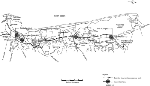
Many geotechnical investigations have been undertaken since the inception of the project, but only the investigations since 1996 are relevant for the present alignment. These investigations are summarized in Table 25.1 and consist of a fieldwork component and a laboratory testing component.
Table 25.1
Recent geotechnical investigations undertaken along the present CKE alignment
| Fieldwork period | Investigation by | Purpose of investigation | Report date |
| December 1996–March 1997 | National Building Research Organisation | Preliminary investigation to establish geological conditions and subsurface material parameters | May 1997 |
| June 1999–October 1999 | National Building Research Organisation | To evaluate subsurface conditions and material parameters at the interchanges and overpasses | November 1999 |
| December 2000–April 2001 | National Building Research Organisation and Engineering and Laboratory Services | To confirm subsoil transition zones and obtain subsurface information at bridges and box culverts for detailed design | July 2001 |
| August 2001–September 2001 | National Building Research Organisation | Additional investigation to establish subsurface conditions and material parameters for bridge foundations | September 2001 |
| August 2001–November 2001 | Additional investigation to establish subsurface conditions and material parameters for soft ground design, over bridges, and box culverts | November 2001 | |
| 2002 | Daewoo–Keangnam Joint Venture (DKJV) | To obtain additional subsurface information during construction | No report |
| September 2003–January 2004 | SMEC International Pty Ltd | Additional investigation to confirm existing information, obtain any missing information, and to evaluate the results of previous soft ground treatment (SGT) | March 2004 |
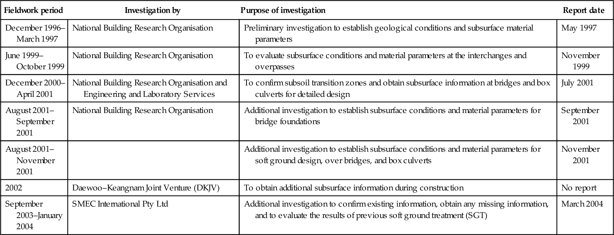
The field investigations comprised drilling, sampling, in situ testing, and groundwater monitoring. The drilling consisted of hand augering, wash boring, and rotary rock coring, and the in situ testing included standard penetration tests, vane shear tests, cone penetration tests, field permeability tests, and in situ resistivity tests. Table 25.2 shows a breakdown of the fieldwork undertaken during each investigation.
Table 25.2
Summary of field investigations undertaken along the CKE alignment
| Report Date | |||||||
| Investigation | May 1997 | November 1999 | July 2001 | September/November 2001 | During construction 2002 | March 2004 | Total |
| Hand augers | 220 | 98 | 11 | – | Records not available | – | 329 |
| Boreholes | 263 | 105 | 132 | 24 | 80 | 604 | |
| Vane shear tests | 103 | – | 68 | – | 44 | 215 | |
| Cone penetrometer tests | – | – | – | 70 | 13 | 83 | |
| Field permeability tests | – | – | 8 | – | 5 | 13 | |
| In situ resistivity test | – | – | – | – | 6 | 6 | |
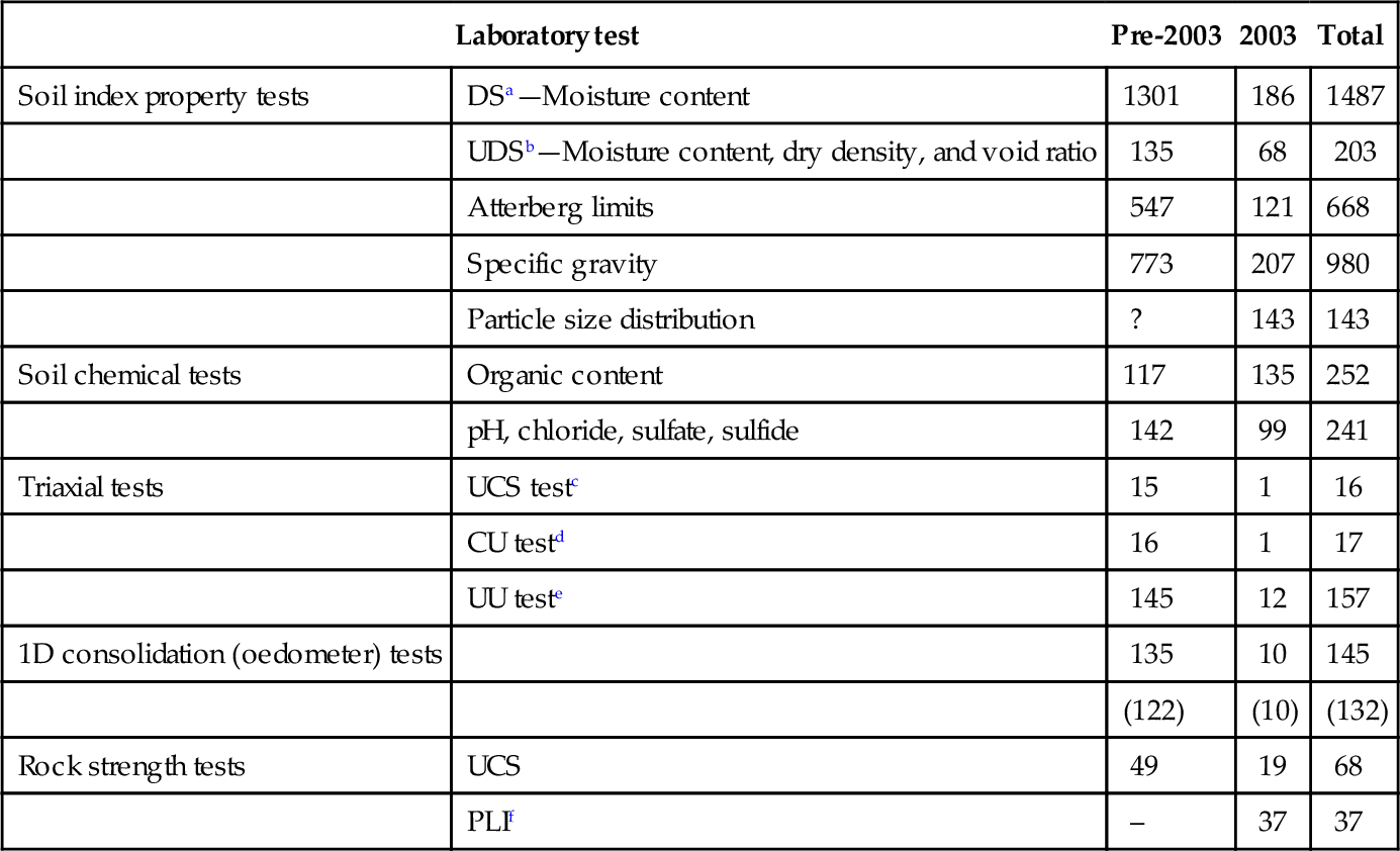
It is noted that access to the field investigation locations was very difficult in marshy areas with very soft peat. Furthermore, due to the very soft nature of the peat, difficulties were also encountered in obtaining undisturbed samples. This fact was taken into consideration when the investigation results were reviewed and interpreted. Extensive laboratory testing was carried out as part of the geotechnical investigations. Table 25.3 shows the laboratory testing that has been undertaken for the project.
Table 25.3
Summary of laboratory testing
| Laboratory test | Pre-2003 | 2003 | Total | |
| Soil index property tests | DSa—Moisture content | 1301 | 186 | 1487 |
| UDSb—Moisture content, dry density, and void ratio | 135 | 68 | 203 | |
| Atterberg limits | 547 | 121 | 668 | |
| Specific gravity | 773 | 207 | 980 | |
| Particle size distribution | ? | 143 | 143 | |
| Soil chemical tests | Organic content | 117 | 135 | 252 |
| pH, chloride, sulfate, sulfide | 142 | 99 | 241 | |
| Triaxial tests | UCS testc | 15 | 1 | 16 |
| CU testd | 16 | 1 | 17 | |
| UU teste | 145 | 12 | 157 | |
| 1D consolidation (oedometer) tests | 135 | 10 | 145 | |
| (122) | (10) | (132) | ||
| Rock strength tests | UCS | 49 | 19 | 68 |
| PLIf | – | 37 | 37 |
Notes:
? indicates tests undertaken but quantum unknown; parentheses indicate a number of tests where secondary consolidation index was calculated.
a DS indicates disturbed samples.
b UDS indicates undisturbed samples.
c UCS indicates unconfined compressive test.
d CU indicates consolidated undrained.
e UU indicates unconsolidated undrained.
f PLI indicates point load index.
25.5 Soft ground treatment and instrumentation
Some embankment sections were constructed to various heights prior to suspension of the work in late 2002. The construction of the embankment over the soft ground areas was generally undertaken in the following manner:
• Placement of a layer of polypropylene geotextile (10 t/m strength) directly over the natural ground surface
• Placement of a layer of sand mat of 1–1.5 m consisting of dredged sea sand over the geotextile
• Implementation of ground improvement measures
• Installation of geotechnical instruments to monitor behavior of the embankment.
• Continuation of placement of embankment
The filling used for embankment construction was a medium- to coarse-grained dredged sea sand stockpiled adjacent to the CKE alignment. The SGTs for the constructed embankments include:
• Preloading with surcharging
• Prefabricated vertical drains (PVD)
• Sand compaction piles (SCP)
• Stone columns (SC)
• Composite treatment consisting of PVDs under full height of embankment and SCPs under the batter sections
At some locations, a berm at the toe of the embankment was also used to assist in maintaining stability during construction. The composite treatment has been used at three locations—Peliyagoda (Ch 1 + 500–1 + 850) and Muthurajawela (Ch 11 + 250–11 + 930 and 12 + 050–12 + 450)—to provide additional stability during construction. The extent of the constructed SGTs along the main alignment is shown in Table 25.4.
Table 25.4
Status of constructed SGTs along alignment
| SGT type | SGT completed (m) |
| Preload and surcharge only | 4378 |
| Prefabricated vertical drains | 1313 |
| Sand compaction piles | 150 |
| Stone columns | 143 |
| Composite treatment | 1242 |
Geotechnical instruments used on the project include settlement plates on top of the sand mat, piezometers at various depths within soft soils, observation wells and inclinometers below the toe of the embankment, and settlement stakes on the surface of embankment. A summary of the installed instruments is shown in Table 25.5.
Table 25.5
Summary of instrumentation
| Location | Settlement plates | Piezometers locations | Piezometer tips | Observation wells | Inclinometer | Settlement stakes |
| Main alignment | 270 | 35 | 58 | 29 | 24 | 170 |
| New Kelani bridge interchange | – | – | – | – | – | – |
| Peliyagoda interchange | 16 | 7 | 11 | 8 | 8 | – |
| Ja-Ela interchange | – | – | – | – | – | – |
| Katunayake interchange | – | – | – | – | – | – |
| Overpasses | – | – | – | – | – | – |
| Total | 286 | 42 | 69 | 37 | 32 | 170 |
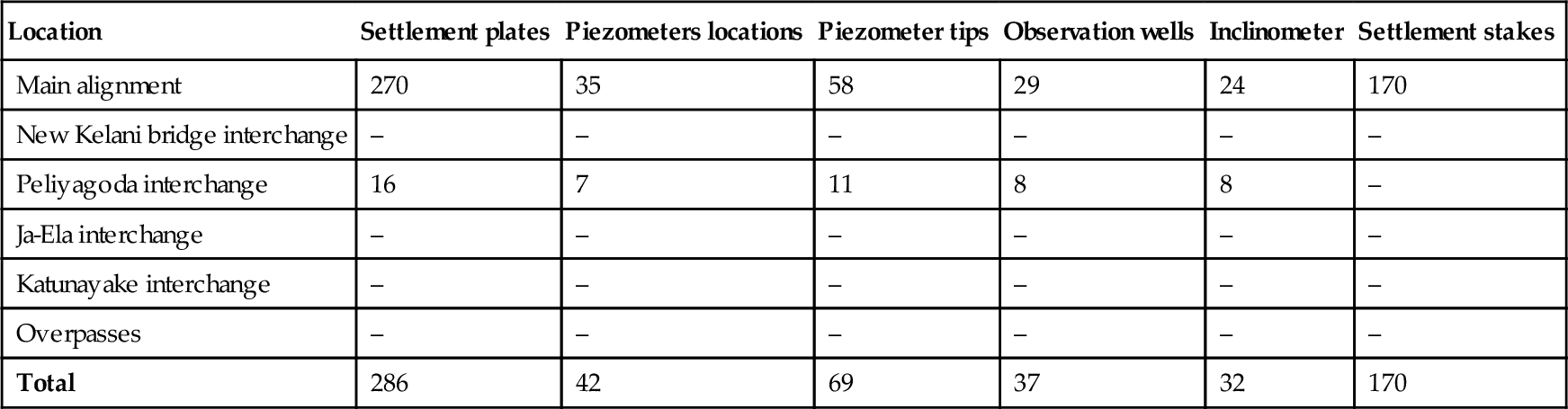
Note: No embankment construction work has been undertaken at the New Kelani bridge interchange, Ja-Ela interchange, Katunayake interchange, and the overpass areas.
Most of the settlement stakes have been damaged since installation; therefore, their monitoring data are not available. Continuous monitoring was undertaken from the inception of construction in June 2001 until August 2003. The SGTs constructed within the very soft Colombo peat along with the monitoring data provide information on the behavior and characteristics of this material.
25.6 Back-analysis
25.6.1 Background information
Extensive monitoring data have been collected since construction of the embankments and they are considered the most reliable information representing the “true” performance of the soft ground underlying the project site. With appropriate interpretation and back-analysis of the available monitoring data, the characteristics and long-term performance of the soft soils can be reliably predicted.
Information required for the back-analysis includes geotechnical models consisting of subsurface profiles and soil parameters, field monitoring data, SGT measures, and construction record of embankments. The monitoring was undertaken over a period of 1.5–2 years in general.
25.6.2 Methodology and approach
Back-analysis is an important process in obtaining realistic geotechnical parameters for the purpose of predicting soft ground performance. The key geotechnical parameters relevant to the back-analysis of the settlement plate data are:
Deformation parameters: Assessment of primary and secondary consolidation settlement. The primary consolidation settlement can be calculated from the coefficient of volume compressibility mv, which can further lead to the Young’s modulus E′ = (1 + v′)(1 − 2v′)/[mv(1 − v′)], with an assumed Poisson’s ratio v′. The secondary compression settlement (creep) can be estimated from the secondary compression index Cɛα = Cα/(1 + e0), where Cα is the coefficient of secondary compression and e0 is the initial void ratio.
Hydraulic conductivity parameters: Assessment of rate of consolidation. The rate of consolidation can be assessed based on the vertical coefficient of consolidation cv, which can be further used to calculate the vertical permeability kv = γwmvcv, where γw is the unit weight of water. As there is no evidence of stratification of the peaty and organic soils, which have large void ratios, it is assumed that kh/kv = 1, or ch/cv = 1, where the subscript h stands for the material property in the horizontal direction. The approach of the back-analysis is described next:
Establish initial geotechnical model: Subsurface profile and the first-pass soil parameters were determined based on the available geotechnical information.
Process settlement plate data: Settlement plate data in conjunction with the levels of embankment as constructed were plotted against logarithm of time. These plots show the magnitude of primary settlement, time at which the primary settlement is completed, and the rate of creep settlement as settlement per log time cycle (mm/log time). By reviewing the creep settlement per log time cycle, embankment sections that have experienced excessive creep settlements may be readily identified.
Select typical sections for back-analysis: Typical sections were selected with considerations of different subsurface conditions, different SGT measures, and being representative of the site conditions.
Determine conditions of analysis: Conditions required for the back-analysis included the as-built embankment status and the SGTs implemented.
Carry out back-analysis: Back-analysis of the primary consolidation settlement was carried out using the finite element program COFEA, which is based on a fully coupled numerical approach that analyses deformation of soil and dissipation of excess pore water pressure simultaneously during the course of consolidation (Hsi, 2000). The construction sequence of the embankment and the SGTs were incorporated in the analysis. The secondary compression settlement was analyzed using a curve-fitting procedure for the linear creep settlement on a logarithm of time scale. The back-analysis attempted to match the predicted settlements with actual site measurements by adjusting soil parameters at various construction stages.
Calibrate geotechnical model: The geotechnical model, mainly the soft soil parameters, was calibrated via the back-analysis process to represent the actual in situ behavior. When adjusting the soil parameters during the process of back-analysis, reference was made to published historical data on other similar materials encountered on projects from local areas and other parts of the world.
Predict long-term performance: The calibrated geotechnical model derived from the back-analysis was then used for the prediction of long-term performance. As the calibrated geotechnical model gives reasonable predictions of soft ground performance over the duration of field monitoring, it is expected that reasonable predictions of long-term performance can be achieved.
It is acknowledged that some settlements had occurred after placement of the sand mat and prior to installation of settlement plates. These initial settlements were not measured by the settlement plates; however, they have been incorporated in the back-analysis using assumed mv and cv values.
25.7 Characteristics of soft soils
25.7.1 General
Soft soils encountered along the CKE alignment are categorized into three material types: peat, organic soil, and clay. The characteristics of these soft soils have been assessed based on field and laboratory test results, settlement plate data, and results of the back-analysis.
25.7.2 Index and physical properties
The index and physical properties, such as natural moisture content, Atterberg limits, unit weight, and organic content are presented in the following subsections.
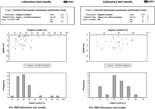
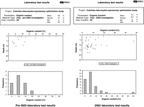
Organic content
More than 250 laboratory organic content tests were undertaken and the results for peat, organic soil, and clay are tabulated in Table 25.6. The classification of the soft soils in terms of peat, organic soil, and clay has been based on field observations and confirmed by the laboratory testing.
Table 25.6
Organic content of peat, organic soil, and clay
| Material type | Data | Pre-2003 | 2003 |
| Organic content (%) | |||
| Peat | Mean | 41 | 38 |
| Range | 10–87 | 3–69 | |
| Organic soil | Mean | 27 | 19 |
| Range | 7–87 | 5–30 | |
| Clay | Mean | 9 | 9 |
| Range | 3–20 | 3–48 | |
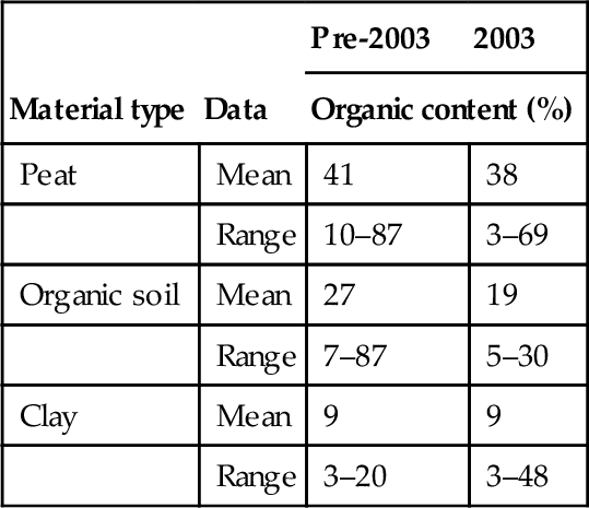
While no specific boundaries were set for each type of material, the peat generally showed an organic content of < 20% with a recorded maximum of 87%, and the organic soils generally had organic contents of between 15% and 35%. Most of the clays had organic contents of > 15%. A distinctive feature of the CKE peat was its fibrous texture.
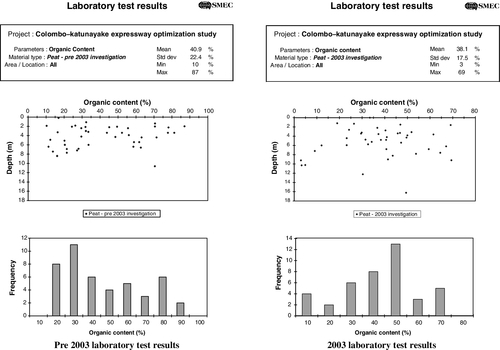
The organic contents for the peat, organic soil, and clay are presented later in Figs. 25.A.1–25.A.3 in the appendix.
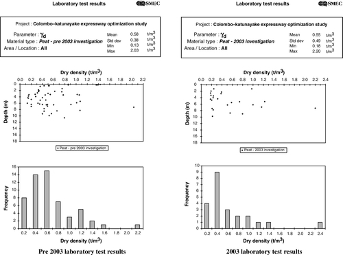
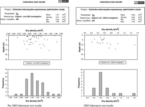
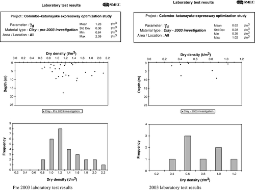
Dry unit weight
The dry unit weights of the soft soils derived from the laboratory testing are shown in Table 25.7. Out of a total of 80 peat samples tested, the dry unit weight of 80% of the samples were below 0.8 t/m3 and only 2 samples had dry unit weights of greater than 1.5 t/m3. The mean dry unit weight for 80% of the samples below 0.8 t/m3 is 0.41 t/m3.
Table 25.7
Dry unit weight of peat, organic soil, and clay
| Material type | Data | Pre-2003 | 2003 |
| Dry unit weight γd (t/m3) | |||
| Peat | Mean | 0.58 | 0.55 |
| Range | 0.13–2.03 | 0.18–2.20 | |
| Organic soil | Mean | 1.01 | 0.63 |
| Range | 0.34–1.84 | 0.23–1.52 | |
| Clay | Mean | 1.23 | 0.62 |
| Range | 0.64–2.09 | 0.30–1.02 | |
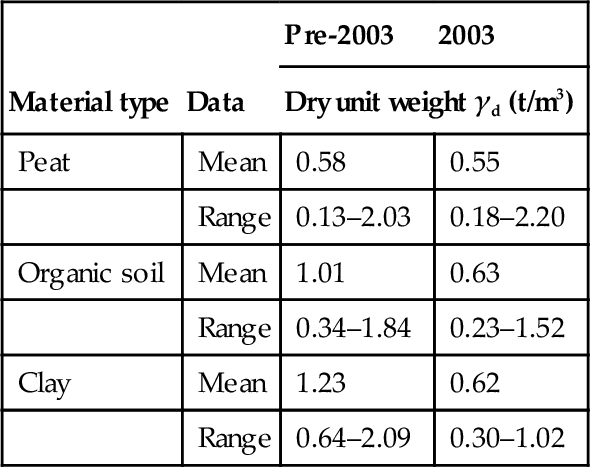
It appears that the dry unit weights obtained for the peat samples along the length of the CKE alignment are slightly higher than the values of 0.35 and 0.33 t/m3 for Peliyagoda and Muthurajawela, respectively, as reported by Ray et al. (1986). The dry unit weight distribution for peat, organic soil, and clay are presented later in Figs. 25.A.4–25.A.6 in the appendix.
Moisture content and Atterberg limits
The moisture contents (MC) for the CKE soft soils are presented in Table 25.8. MC for all undisturbed samples were extracted from samples saturated in the consolidation ring. As the groundwater level is very close to the surface and most of the soft soil samples were collected below the groundwater table, it is assumed that the MC obtained from the saturated samples would be representative of the in situ condition.
Table 25.8
Moisture content of peat, organic soil, and clay
| Material type | Data | Pre-2003 | 2003 | ||
| DS (%) | UDS (%) | DS (%) | UDS (%) | ||
| Peat | Mean | 266 | 242 | 302 | 295 |
| Range | 13–851 | 23–631 | 23–657 | 28–651 | |
| Organic soil | Mean | 100 | 76 | 106 | 145 |
| Range | 2–548 | 10–150 | 31–267 | 28–304 | |
| Clay | Mean | 39 | 52 | 38 | 148 |
| Range | 14–340 | 20–179 | 14–153 | 56–280 | |
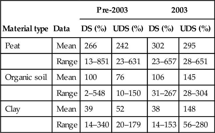
Note: DS, disturbed sample; UDS, undisturbed sample.
As significant moisture losses were observed during collection of some peat samples, it can be expected that the MC obtained from the disturbed samples would be lower than that obtained from the undisturbed samples. However, such a trend was not evident. The distribution of MC with depth obtained from testing of disturbed and undisturbed samples of peat, organic soil, and soft clay are presented later in Figs. 25.A.7–25.A.9 in the appendix. Atterberg limits for the soft soils are tabulated in Table 25.9.
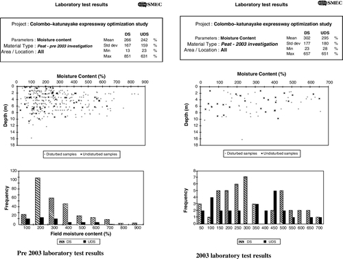


Table 25.9
Liquid and plastic limits of peat, organic soil, and clay
| Material type | Data | Pre-2003 | 2003 | ||
| LL (%) | PL (%) | LL (%) | PL (%) | ||
| Peat | Mean | 78 | 37 | 80 | 47 |
| Range | 28–110 | 13–57 | 21–225 | 18–119 | |
| Organic soil | Mean | 64 | 34 | 72 | 46 |
| Range | 28–140 | 21–56 | 25–218 | 19–121 | |
| Clay | Mean | 64 | 27 | 47 | 26 |
| Range | 22–113 | 13–46 | 20–110 | 11–70 | |

Note: LL, liquid limit; PL, plastic limit.
The liquid limit for the majority of the peat and organic soil samples were above 50%, indicating that these materials are highly plastic. Out of 241 clay samples tested for the liquid limit, less than 10% of the values were below 35%, and 88% of the values were between 35% and 100%. Two peat samples, three organic soil samples, and six clay samples had liquid limits in excess of 100%, indicating the extent of compressibility of the soft soils.
The liquid limits, plastic limits, and natural moisture contents for the soft soils along the CKE alignment are presented in Fig. 25.3. Three organic soil samples had MC greater than 400% and one clay sample had an MC in excess of 200%. These results have been excluded in the figure for clarity of the presentation. It is also noted that MC and Atterberg limits tested from samples collected away from the main CKE alignment are not included in Fig. 25.3.
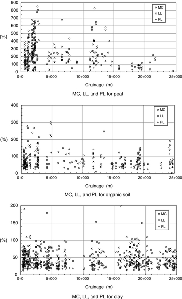
Figure 25.3 shows the variation of the natural moisture content along the proposed CKE alignment. High MC encountered in the areas of Peliyagoda (Ch 0 + 500–3 + 000), Welikadamulla (Ch 5 + 300–6 + 900), and Muthurajawela (particularly Ch 11 + 000–15 + 000) indicate the extent of CKE soft soil affinity to water. It has been reported that most of the peaty soils tested in Sri Lanka have MC between 50% and 500% (Tennekoon et al., 1993). The latest work for the CKE project includes about 300 samples tested for MC and shows that the natural moisture contents of the Colombo peats could be higher than previously encountered.
25.7.3 Strength parameters
Undrained shear strength
The undrained shear strength, Su, of the soft soils encountered along the CKE alignment was assessed by reviewing the in situ vane shear tests, pocket penetrometer tests, and the unconsolidated undrained (UU) triaxial tests. The vane shear and UU test results for peat, organic soil, and clay are tabulated in Table 25.10 and presented in a graphical form later in Figs. 25.A.10–25.A.12 in the appendix.
Table 25.10
Undrained shear strength of peat, organic soil, and clay
| Material type | Data | Pre-2003 | 2003 | ||
| UU triaxial (kPa) | Vane (kPa) | UU triaxial (kPa) | Vane (kPa) | ||
| Peat | Mean | 12 | 21 | 29 | 38 |
| Range | 12–64 | 4–103 | 26–32 | 7–83 | |
| Organic soil | Mean | 22 | 27 | 30 | 45 |
| Range | 3–45 | 3–70 | 15–37 | 6–72 | |
| Clay | Mean | 32 | 40 | 25 | 10 |
| Range | 10–172 | 14–87 | 15–33 | 10–10 | |
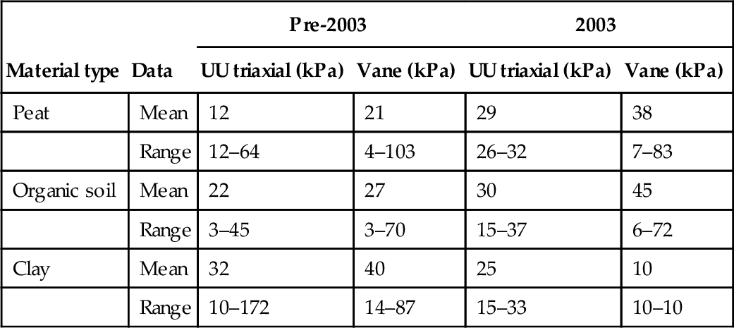


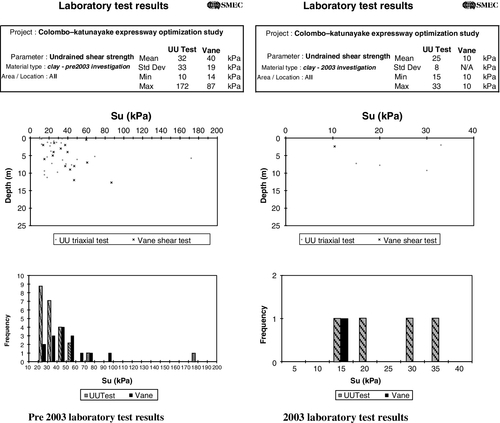
One of the objectives of the 2003 investigation was to assess the strength gain of the material below the constructed embankments. Therefore, some of the undrained shear strength testing undertaken in 2003 was on material that had been subjected to embankment loading. It is evident that the undrained strength increases for peat and organic soils, as shown in Table 25.10. Figures 25.A.10 and 25.A.11 show that when the isolated upper values for the pre-2003 results are discounted, the strength gains due to consolidation are evident.
The undrained strengths from the 2003 investigation for soft clay in Table 25.10 appear to be less than what was obtained prior to construction. However, a more detailed review of the results for 2003 indicates that only five tests were undertaken in clay and most of them were undertaken in the Peliyagoda area where the soft soil materials extend to depths of 10–12 m and are very soft. The limited undrained clay strength results available for this area indicate that they are comparable with the results obtained in 2003. This is in line with the fact that the embankments in this area are not constructed or still at ground level.
The results in Table 25.10 also indicate that the in situ vane shear strengths are generally higher than the laboratory UU triaxial test results.
Drained strength
The drained strength parameters (i.e., c′ and ϕ′) interpreted from the consolidated undrained (CU) triaxial tests are tabulated in Table 25.11. For the 2003 investigation, difficulties in sample preparation for the soft soils were encountered and as such only one CU triaxial test was undertaken. This result also appeared to be erroneous and has therefore been excluded from the analysis.
Table 25.11
Drained shear strength parameters of peat, organic soil, and clay
| Material type | Data | Pre-2003 | ||
| No. of Tests | c′ (kPa) | ϕ′(deg) | ||
| Peat | Mean | 6 | 6 | 23 |
| Range | 0–18 | 19–25 | ||
| Organic soil | Mean | 4 | 11 | 25 |
| Range | 8–12 | 21–27 | ||
| Clay | Mean | 6 | 13 | 24 |
| Range | 4–29 | 10–32 | ||

Only a few CU triaxial tests were undertaken in the investigations prior to 2003. The results indicate that the peats exhibit a small effective cohesion generally in the range of 5–8 kPa and the organic soils and clay show an effective cohesion in the range of 8–12 kPa. While the effective friction angle for four of the peat samples are between 22° and 25°, the effective friction angle for three of the organic soil samples lie between 25° and 27°. The effective friction angles for the clay samples are generally between 23° and 25°, with two values greater than or equal to 29°.
It is noted that there were difficulties in recovering undisturbed samples of very soft peat and organic soil. Therefore, the results shown in Table 25.11 may not be representative of the soft soils.
25.7.4 Deformation parameters
Void ratio
The void ratios extracted from the consolidation testing for the CKE soft soils are presented in Table 25.12. The void ratio of peat was generally between 1 and 8. This shows that for most of the peat samples the volume of voids within the soil mass was between 50% and 90%, indicating extremely high compressibility of the peats.
Table 25.12
Void ratio of peat, organic soil, and clay
| Material type | Data | Pre-2003 | 2003 |
| Void ratio e0 | |||
| Peat | Mean | 4.45 | 4.78 |
| Range | 0.66–11.61 | 0.66–9.80 | |
| Organic soil | Mean | 1.88 | 2.75 |
| Range | 0.54–3.74 | 0.78–6.76 | |
| Clay | Mean | 1.24 | 2.04 |
| Range | 0.48–2.61 | 1.57–3.38 | |

Ray et al. (1986) states void ratios of 5.08 and 4.16 for peat in Peliyagoda and Muthurajawela, respectively. The results from this study show that the average void ratios for the Peliyagoda and Muthurajawela areas are 4.80 and 4.36, respectively, and compare well with the previous findings. The results also show that the void ratio, and thus the compressibility, is less for the organic soils than for the peats, while the soft clays are the least compressible.
The testing in 2003 focused more on the areas with deep soft soils, particularly at Peliyagoda, Welikadamulla, and Muthurajawela. The pre-2003 investigations covered the entire alignment, which also includes less compressible areas. As a result, the void ratios appear to be higher from the 2003 investigation.
Compression and recompression indices
The compression and recompression indices extracted from the consolidation testing for the soft soils are presented in Table 25.13. The compression indices as shown in the table indicate that the compressibility of the soft soils decreases from peat to organic soil to soft clay. The mean recompression index is between 7% and 12% of the compression index.
Table 25.13
Compression and recompression indices of peat, organic soil, and clay
| Material type | Data | Pre-2003 | 2003 | ||
| Compression index Cc | Recompression index Cr | Compression index Cc | Recompression index Cr | ||
| Peat | Mean | 0.310 | 0.027 | 0.470 | 0.034 |
| Range | 0.044–0.633 | 0.002–0.125 | 0.328–0.623 | 0.024–0.075 | |
| Organic soil | Mean | 0.211 | 0.022 | 0.186 | 0.017 |
| Range | 0.043–0.529 | 0.005–0.080 | 0.121–0.271 | 0.006–0.027 | |
| Clay | Mean | 0.147 | 0.018 | – | – |
| Range | 0.048–0.310 | 0.003–0.046 | – | – | |
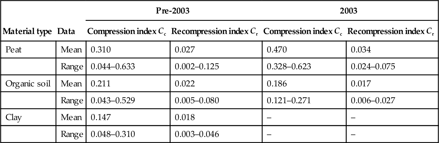
Note: No consolidation tests have been undertaken on soft clay samples for the 2003 investigation.
Overconsolidation ratio
The overconsolidation ratios (OCRs) for the soft soils as interpreted from the oedometer tests are presented in Table 25.14. The preconsolidation pressure was determined from the oedometer tests.
Table 25.14
OCR of peat, organic soil, and clay
| Material type | Data | Pre-2003 | 2003 |
| Overconsolidation ratio | |||
| Peat | Mean | 7.4 | 1.3 |
| Range | 0.3–80 | 0.7–2.5 | |
| Organic soil | Mean | 26.6 | 0.5 |
| Range | 0.3–600 | 0.3–0.6 | |
| Clay | Mean | 10.6 | – |
| Range | 0.2–120 | – | |
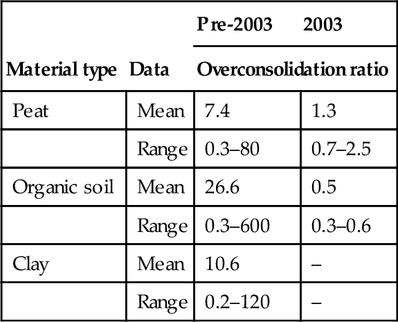
Note: Only three consolidation tests were undertaken on the organic soil samples for the 2003 investigation. No consolidation tests were undertaken on soft clay samples for the 2003 investigation.
The OCR for peat was generally between 0.4 and 7. The OCRs > 7 were from peat samples collected from less than 0.5 m depth. These high pre-2003 values are most likely due to effects of desiccation or variation of the water table. When these high OCR values are removed, the mean OCR for the peat is 1.5, indicating that the peat is generally normally consolidated or slightly overconsolidated.
The OCR for organic soil was generally between 0.5 and 7. The OCRs > 7 were from samples at shallow depths of < 0.3 m. If these values are ignored, the mean OCR for organic soil is 2.1. The OCR for clay was generally between 0.5 and 10. The OCRs > 10 were from samples at shallow depths of < 0.6 m. If these values are removed, the mean OCR for the soft clays is 3.5.
Coefficient of volume compressibility
The coefficient of volume compressibility, mv, extracted from the consolidation testing and the back-analysis findings are presented in Table 25.15. In determining which laboratory mv value to use in the statistical analysis, the proposed embankment heights were used to estimate the final loading at the test sample location and the mv value corresponding to the expected final stress was chosen for the analysis. The back-analysis of the monitoring data took into consideration the reduction of mv as the height of the embankment increased.
Table 25.15
Coefficient of volume compressibility of peat, organic soil, and clay
| Material type | Data | Pre-2003 lab tests | 2003 lab tests | Back-analysis |
| Coefficient of volume compressibility mv (m2/MN) | ||||
| Peat | Mean | 2.24 | 2.67 | N/A |
| Range | 0.10–7.49 | 1.20–4.20 | 0.5–7.6 | |
| Organic soil | Mean | 1.20 | 0.94 | N/A |
| Range | 0.20–3.70 | 0.50–1.32 | 0.6–5.0 | |
| Clay | Mean | 0.68 | – | N/A |
| Range | 0.10–1.60 | – | 0.2–2.5 | |
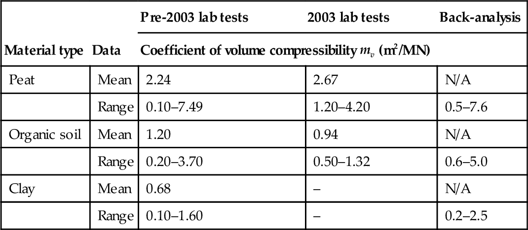
Note: No consolidation tests were undertaken on soft clay samples for the 2003 investigation.
The laboratory test results and the back-analyzed mv values were plotted against vertical stress, as shown in Fig. 25.4 for peat, organic soil, and soft clay. The back-analyzed mv values for peat were in the range of 0.5–7.6 m2/MN and were generally higher than that for organic soil (0.6–5 m2/MN) and clay (0.2–2.5 m2/MN), indicating greater compressibility for peat than for organic soil and clay.
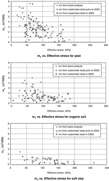
The lower and the upper bounds of the mv range assumed in the back-analyses for peat, organic soil, and clay are shown in Fig. 25.5.

Coefficient of secondary consolidation
The modified secondary compression indices, Cɛα = Cα/(1 + e0), for the soft soils have been calculated using the Cα values derived from the laboratory testing and are tabulated in Table 25.16.
Table 25.16
Modified secondary compression index of peat, organic soil, and clay from oedometer tests
| Material type | Data | 2003 lab tests | Back-analysis |
| Modified secondary compression index Cα/(1 + e0) (%) | |||
| Peat | Mean | 4.06 | – |
| Range | 1.78–9.71 | 1–10 | |
| Organic soil | Mean | 2.96 | – |
| Range | 1.96–4.06 | 1–4 | |
| Clay | Mean | – | – |
| Range | – | 0.5–2.5 | |
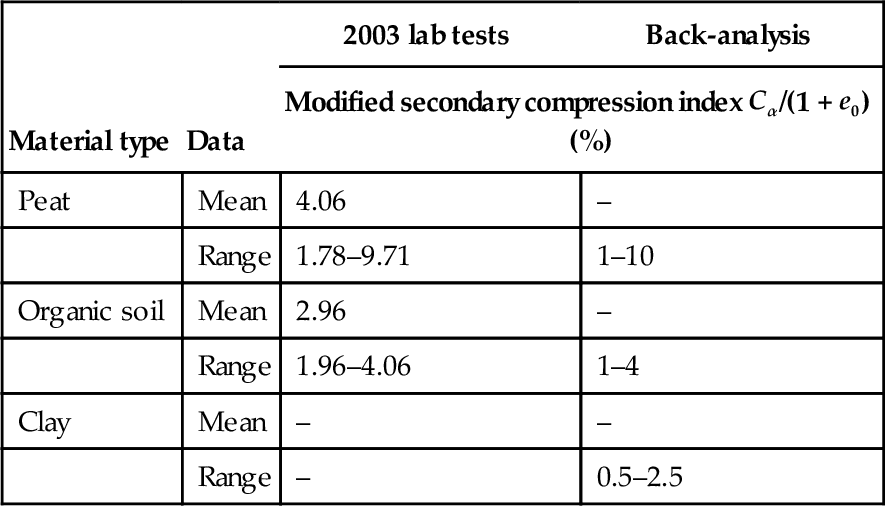
Note: No consolidation tests were undertaken on soft clay samples for the 2003 investigation.
The data from the pre-2003 investigations appear to be questionable and are excluded from the analysis. Figure 25.6 shows the distribution of the back-analyzed Cα/(1 + e0) for peat, organic soil, and clay along the alignment. The back-analyzed Cα/(1 + e0) values were generally in the range of 2–8% for peat, 1–4% for organic soil, and 1–2% for soft clay.

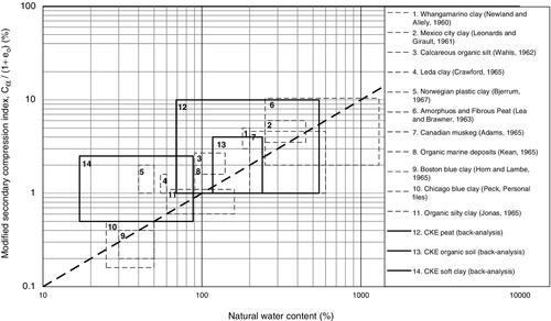
Figure 25.7 shows the relationship between the modified secondary compression index (from back-analysis) and the natural water content for the peat, organic soil, and clay of the CKE project together with other published data. When assessing the range of values for the organic soils, one MC result of 10% was excluded from the results due to its isolated extremity. The Cα/(1 + e0) for the CKE soft clays appear to be higher than that for other reported clays.
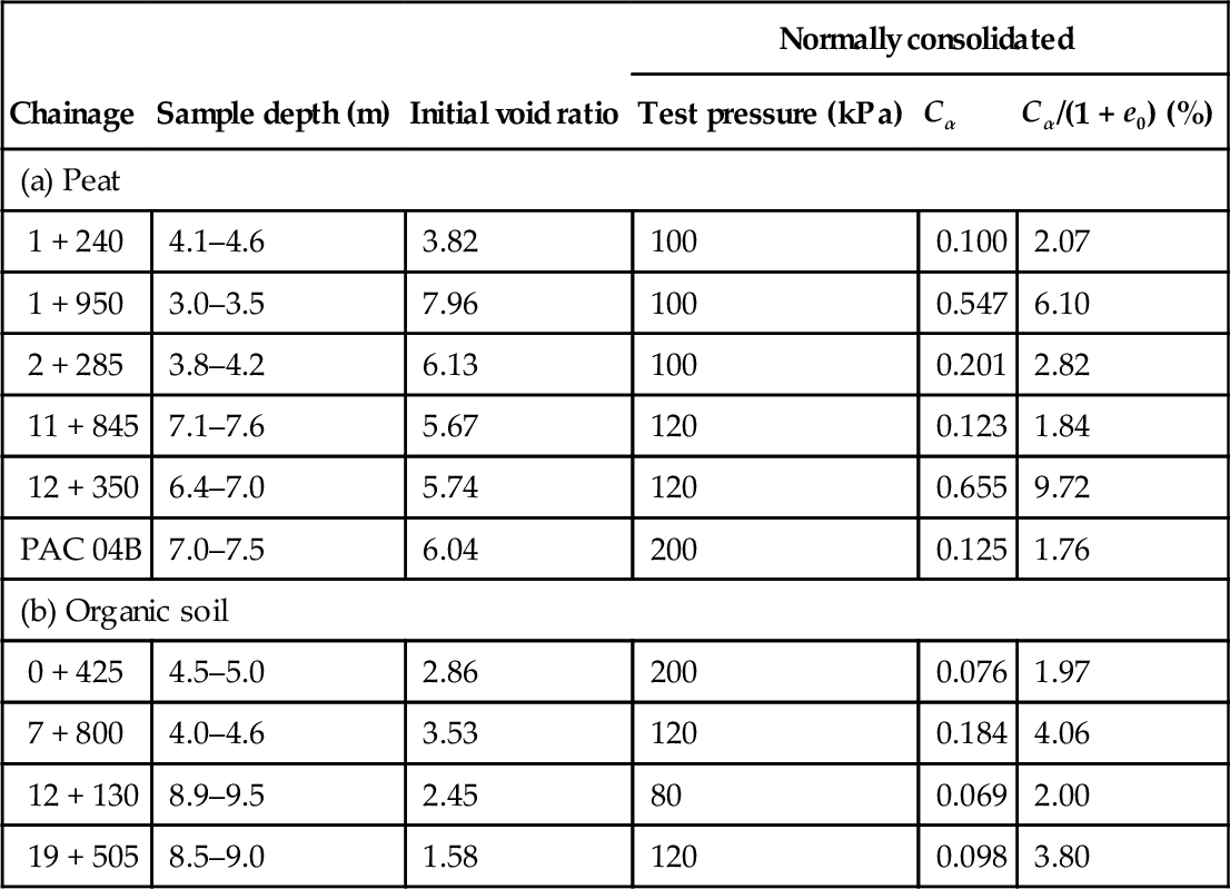
Laboratory oedometer tests with extended loading stages were undertaken in 2003 to assess creep settlements in normally and overconsolidated soft soils. The test procedure generally consisted of stepped load increments and calculation of the corresponding void ratios. At a loading stage approximately equal to the proposed embankment load, the loading was held for an extended period (generally ~ 7 days) for the sample to consolidate well beyond the completion of the primary consolidation stage, and thus well into the secondary compression stage.
Thereafter, the loading was increased again as per the normal testing procedure. During the unloading stage, the load was again held for an extended period at the approximate proposed embankment load. The creep settlement for the overconsolidated soils were found to be negligible compared with the normally consolidated soils. The summary of the test results for normally consolidated soils under equivalent embankment loads is presented in Table 25.17.
Table 25.17
Secondary compression index for normally consolidated peat and organic soil
| Chainage | Sample depth (m) | Initial void ratio | Normally consolidated | ||
| Test pressure (kPa) | Cα | Cα/(1 + e0) (%) | |||
| (a) Peat | |||||
| 1 + 240 | 4.1–4.6 | 3.82 | 100 | 0.100 | 2.07 |
| 1 + 950 | 3.0–3.5 | 7.96 | 100 | 0.547 | 6.10 |
| 2 + 285 | 3.8–4.2 | 6.13 | 100 | 0.201 | 2.82 |
| 11 + 845 | 7.1–7.6 | 5.67 | 120 | 0.123 | 1.84 |
| 12 + 350 | 6.4–7.0 | 5.74 | 120 | 0.655 | 9.72 |
| PAC 04B | 7.0–7.5 | 6.04 | 200 | 0.125 | 1.76 |
| (b) Organic soil | |||||
| 0 + 425 | 4.5–5.0 | 2.86 | 200 | 0.076 | 1.97 |
| 7 + 800 | 4.0–4.6 | 3.53 | 120 | 0.184 | 4.06 |
| 12 + 130 | 8.9–9.5 | 2.45 | 80 | 0.069 | 2.00 |
| 19 + 505 | 8.5–9.0 | 1.58 | 120 | 0.098 | 3.80 |
25.7.5 Hydraulic conductivity parameters
Coefficient of consolidation
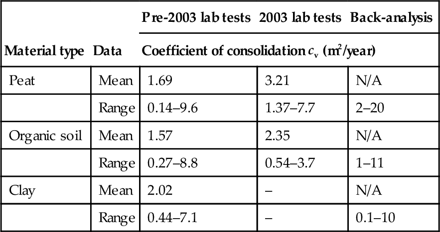
The coefficients of consolidation, cv, for the soft soils from laboratory testing and back-analysis are shown in Table 25.18. In determining which laboratory cv value to use in the statistical analysis, the proposed embankment heights were used to estimate the final loading at the test sample location and the cv value corresponding to the expected final stress was chosen for the analysis. These laboratory test results and the back-analyzed cv values were plotted against vertical stress as shown in Fig. 25.8.
Table 25.18
Coefficient of consolidation of peat, organic soil, and clay
| Material type | Data | Pre-2003 lab tests | 2003 lab tests | Back-analysis |
| Coefficient of consolidation cv (m2/year) | ||||
| Peat | Mean | 1.69 | 3.21 | N/A |
| Range | 0.14–9.6 | 1.37–7.7 | 2–20 | |
| Organic soil | Mean | 1.57 | 2.35 | N/A |
| Range | 0.27–8.8 | 0.54–3.7 | 1–11 | |
| Clay | Mean | 2.02 | – | N/A |
| Range | 0.44–7.1 | – | 0.1–10 | |
Note: Four unusually high cv values in the range of 60–125 m2/year for peat obtained from the back-analysis of settlement plate data at chainages 10 + 5 35 and 14 + 350 and four unusually high cv values in the range of 25–400 m2/year for organic soil obtained from the back-analysis of settlement plate data at chainages 9 + 550 and 10 + 535 were excluded from the statistical analysis. No consolidation tests were undertaken on soft clay samples for the 2003 investigation.

The back-analysis revealed that the cv values reduced as construction of the embankment progressed. This is considered reasonable, and is consistent with research findings (Mesri and Rokhsar, 1974). In general, the cv values for peat were found to be between 2 and 20 m2/year and 1–10 m2/year for organic soil and 0.5–5 m2/year for clay. This suggests that the peat is more permeable than the organic soil and clay.
Figure 25.8 indicates that the back-analyzed cv values for the peat, organic soil, and soft clay are notably higher than that obtained from the laboratory testing. The lower and the upper bounds of the cv range assumed in the back-analyses for peat, organic soil, and clay are shown in Fig. 25.9.

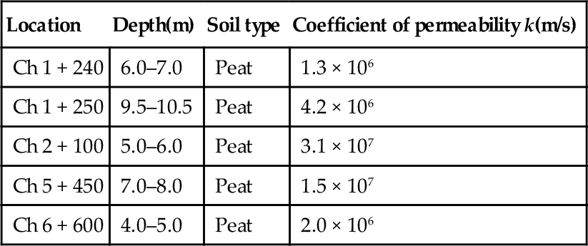
Permeability
Table 25.19 presents the results of the rising head field permeability tests undertaken in the 2003 investigation. The field permeability test results indicate that the coefficient of permeability of peat is in the order of 10− 6–10− 7 m/s. Tennekoon et al. (1993) quote coefficient of permeability values ranging from 1 × 10− 5 m/s for fibrous peats to 1 × 10− 7 m/s for amorphous peats.
25.7.6 Performance of embankments over CKE soft soils
The embankment monitoring data for the project provide an excellent source of information on the performance of embankments constructed over soft soils encountered in and around Colombo. Figure 25.10 shows the settlement along the alignment with the corresponding fill thicknesses, where the unit weight of the compacted fill is assumed to be 17.4 kN/m3 based on the test results.

Figure 25.10 shows that at approximate chainage 2 + 000, total settlements of up to 7.5 m occurred for fill thicknesses of similar magnitude. In these areas, all fills placed settled to or below the original ground level. Around chainage 12 + 000, settlements of up to 5 m were recorded under various thicknesses of fill ranging from 4–9 m. As shown in Fig. 25.2, these areas have combined soft soil thicknesses of more than 10 m.
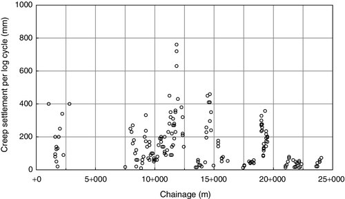
Figure 25.11 shows the measured rates of creep settlement plotted on a logarithm of time scale. Review of the results presented in the figure indicates that the measured rates of creep settlement ranged approximately between 10 and 750 mm/log time cycle with the maximum value being recorded close to chainage 12 + 000.
The measured rates of creep settlements were used to predict the long-term settlements over a 10-year period. These results are presented in Fig. 25.12. The settlements predicted for 10 years using the back-analyzed Cα/(1 + e0) values are also presented in the figure.
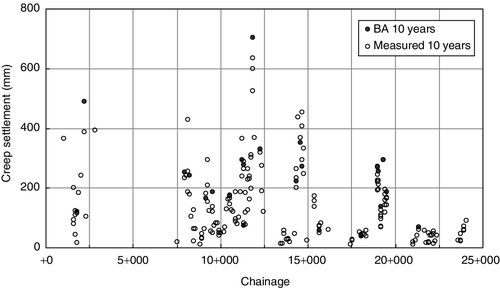
The predictions for the two sets of long-term settlements are comparable and show large variation in residual settlement along the length of the route. Maximum predicted settlement is 700 mm in 10 years.
25.8 Conclusion
The Colombo–Katunayake Expressway is a major highway project recently completed in Sri Lanka. Extensive geotechnical studies have been undertaken to assess ground conditions of the expressway embankments that are founded over the very soft Colombo peats and organic soils. The studies primarily consisted of geotechnical investigations, review of the investigation results, and back-analysis of the constructed embankment behavior using the field-monitoring data.
The investigation results provided bounded parameters that may be used to assess the behavior of very soft peats, organic soils, and clays encountered in Colombo.
The monitoring data were used to derive soil parameters for the prediction of long-term embankment performance. Back-analysis was carried out to simulate the actual conditions as built so that “realistic” soil parameters could be derived. The rate (cv) and magnitude (mv) of consolidation are dependent on fill height. However, these parameters only have a role during the construction stage and have no influence on the long-term performance.
The results of the back-analysis show that both the mv and cv values reduced as construction of the embankment progressed. This is considered reasonable, and is consistent with research findings.
The field measurements spanned over a period of 300–700 days. Full consolidation was mostly achieved followed by creep settlements. The settlement record demonstrates that the creep settlement follows a straight line on the settlement versus logarithm of time plot.