2.4. Development Frameworks
Information systems development involves at least four worlds: the subject world, the system world, the usage world, and the development world (Jarke et al. 1992). The subject world is the universe of discourse, or business domain, typically part of the real world. The system world is the information system’s model of the UoD, and hence is a formal abstraction. The usage world is the organizational world in which the system is to function and includes the community of users of the system, their user interfaces to the system, associated activities, and so on. This is sometimes called the environment of discourse. The development world covers the environment and processes used to develop the system, including the modelers and programmers, their design methods and rationale, project schedules, and so on.
The system world is sometimes called the information system in the narrow sense, while the combination of the four worlds is the information system in the broad sense, since it includes all related human factors. Specialists who focus on the system world are called “dry” (they deal with formal aspects), whereas those that focus on the other three worlds are called “wet” (they are willing to get their hands wet dealing with the informal, softer aspects). In practice, both dry and wet approaches are needed.
Determining automation boundaries (how much of the subject world will be managed by the system world) is a critical decision. We should first determine the services to be provided by the business (i.e., the essential business processes). Then for each of these services we need to decide whether it will be fully automated, semi-automated, or manual.
Developing an information system for a business domain is essentially a problem-solving process. This general process may be broken down into four main stages: (1) defining the problem, (2) devising a plan, (3) executing the plan, and (4) evaluating what happened. Two of the most generally useful problem-solving strategies are to divide the problem into a number of subproblems and deal with these individually, and to try a simpler version of the problem first.
When the problem-solving process involves development of computer software, it may be refined into the five-stage software life cycle shown in Figure 2.8: specify (say what the software is to do), design (decide how to do it), implement (code it), test (check that it works), and maintain (keep it working). In the naive “waterfall” version of this process, the path through these five stages is a simple sequence. In practice, however, the process is typically cyclic in nature, as indicated by the dotted arrows.
Figure 2.8. The software life cycle, with iterations.

If a need for change is detected at a later stage of the cycle, it is often necessary to return to one of the earlier stages. Moreover, large development projects are usually best divided into small projects, which can be further divided into components, each having its own cycle. The additional cycles at the right of Figure 2.8 depict further iterations, each of which can be refined into a multistage cycle as shown on the left. In this iterative approach to development, the more essential or critical components are often developed first, to minimize the risk of the project failing overall.
When the software is an information system, the development cycle for each component may be refined further into the following typical phases.
Requirements analysis
Conceptual design: data, processes
Logical design: data, processes
Basic physical design: data, processes
Basic external design: data; processes
Prototyping
Completion of design
Implementation of production version
Testing and validation
Release of software, documentation, and training
Maintenance
In practice, these phases often overlap, feedback cycles are common, and some phases might be omitted. Many detailed procedures exist to flesh these phases.
A feasibility study identifies the main objectives of the proposed information system and determines which components may be implemented with known resources (e.g., budget allocations and staff). It examines the cost-effectiveness of alternative proposals and assigns priorities to the various system components. The cost/benefit analysis might reveal that some objectives are unrealistic or that some of the objectives can be best achieved by improved manual procedures rather than by use of computers.
Assuming the project is approved, a detailed requirements analysis is undertaken to determine just what the system is required to do. Components of the system are delineated, and people familiar with the relevant application areas are interviewed, including domain experts, intended users, and policy makers. Interviews may be supplemented by questionnaires. Relevant documentation is examined (e.g., forms, reports, charts, policy manuals, even code from legacy systems to be reengineered). Where no such documentation is available, the domain experts are requested to invent examples of the kinds of information to be recorded. Simple diagrams are often used to clarify how the information system is to interact with the business environment. The main operations or transactions to be supported are identified and prioritized, and estimates are made of their expected data volumes, frequencies, and required response times.
The output of this requirements collection and analysis phase is a requirements specifications document detailing functional requirements, nonfunctional requirements (e.g., performance), and maintenance information (e.g., anticipated changes). This document should be unambiguous, complete, verifiable (there is a way to check whether the requirements are satisfied), consistent (requirements do not contradict one another), modifiable (changes can be made easily and safely), traceable (requirements can be tracked to their origins, and are identifiable across different versions of the document), and usable (by current and future users of the document).
Various textual and graphical notations are used for different aspects of the requirements specification. Some process-oriented notations (e.g., use case diagrams, context diagrams, data flow diagrams) are discussed in a later chapter. For large, complex projects the requirements analysis stage might take several months. As fact-oriented modeling uses verbalization of familiar examples to clarify the UoD, its conceptual design method is also useful for analysis of data requirements.
One way to measure the progress of a requirements activity employs the following three dimensions of requirements engineering: specification (opaque, fair, complete), representation (informal, semiformal, formal), and agreement (personal view, common view). The further one is along these dimensions, the better (Pohl, 1994).
With the understanding that phases may overlap, the next stage in the information systems life cycle is conceptual design. This is sometimes simply called ”analysis”, to distinguish it from the later stages of logical and physical design. With large applications, subproblems or components of a more manageable size might be selected, an architecture specified for coupling components, and a conceptual subschema designed for each. The subschemas may then be integrated within a global conceptual schema. In this text, the problems discussed are small enough for us to design the whole conceptual schema without needing to first design subschemas. However, the main design process itself is broken up into various stages. For example, fact types are identified before adding constraints.
Experienced modelers often notice similarities between new applications and previous ones they or others have designed. In this case, significant savings in the design effort may result from judicious reuse of strategies adopted in their earlier models. For example, if we have already modeled a university library system, and now have to model a video rental business, there are many features of the earlier model that may be reused. We might choose to identify an object type Loan in a similar way and either adopt or adapt several fact types from the earlier application. By abstracting similar, specific concepts (e.g., “book”, “compact disc”) to more general concepts (e.g., “rentable item”), it is easier to recognize a new application as related to earlier ones.
In recent years, a substantial and growing body of work on design patterns and best practices has been developed to facilitate reuse. Many resources are available that provide basic design patterns and templates for a variety of business domains. Large commercial packages for Enterprise Resource Planning (ERP) can be adapted to handle various functions of a business (e.g., order processing, payroll management). To widen the scope of their reuse, such packages often model practices at a very high level of abstraction, which can make them harder to apply to concrete cases. The rise of component technology, design patterns, and ERP packages has seen a move from “Build or Buy” to “Build and Buy and Reuse”.
Over the years, many dimensions or perspectives have been suggested for capturing different aspects of information systems design. One classic survey of information systems design methods identified three design perspectives: data, process, and behavior (Olle et al. 1991). The data-oriented perspective focuses on what kinds of data are stored in the database, what constraints apply to these data, and what kinds of data are derivable. The process-oriented perspective examines the processes or activities performed to help understand the way a particular business operates. Processes and their agents are described, as well as information flows between processes and other components. Often, a complex process is refined into several subprocesses. The behavior-oriented perspective looks at how events trigger actions. Often, an activity analysis may be rephrased in terms of an event analysis, or vice versa.
It is important to specify the information needed and conditions sufficient for a process to execute or “fire”. For example, the process of retrieving an account balance might be triggered by the event of a client requesting an account balance, and require input of information from the client (e.g., client number and account type) as well as from the relevant database tables. Since the dividing line between process and behavior is often blurred, we’ll follow one common practice of bundling any discussion of processes, events, operations, activities, and so on into a single perspective, which we’ll call “process”. From that viewpoint there are just two main perspectives: data and process. Various techniques such as workflow models have been developed to enable business process modeling, as discussed in Chapter 15.
Decades ago, systems were designed largely from the process perspective, but this proved to be inefficient and unreliable in many cases. The data perspective became dominant for information systems development, since it was more fundamental and much more stable. Business processes change continually, but the underlying data tends to undergo only minor changes by comparison. Recently, object-oriented modeling has provided one way to combine data and process perspectives, with objects encapsulating data and operations. Unfortunately, this combination is often specified at a subconceptual level, and hence this integration is not as rosy as it seems.
If designed correctly, the conceptual schema provides a formal model of the structure of the UoD. Once this semantic modeling is completed, we perform a mapping of the conceptual design to a logical design expressed in terms of the generic data model of the implementation target(s). For example, we might map a conceptual schema to a relational schema. CASE tools can perform this mapping automatically. Once the logical design is determined, a basic physical design can be undertaken. The logical design is adapted to the specific DBMS(s) or coding language(s) being used, and various strategies (e.g., indexes or clustering) are specified to improve the efficiency of the physical design.
The basic external design of an information system involves determining which kinds of data and operations will be accessible to which user groups, and designing appropriate human-computer interfaces for these groups. Typically, access rights tables are constructed for different user types, decisions are made about what functions to support on different screen forms, and the layout of screen forms and menus is decided. The external design can include cross references to the internal design (e.g., to show which forms access which tables or classes).
Except for trivial applications, the next stage of the life cycle usually involves prototyping. A prototype is a simplified version of the intended product that is used to gain early feedback from users on the quality of the design. It aims to cover the major functions in the requirements specification, but usually omits most of the error checking and finer details required for the final version, and uses only a small set of sample data. Because early feedback is more important than efficiency at this stage, the prototype might be coded in a higher level language than the one(s) ultimately used. For user-interface design, the initial prototypes may simply be drawn on paper: these are called “paper prototypes”. The prototypes are demonstrated to the clients, and their feedback is used to revise the requirements and designs where necessary.
Once a prototype is accepted, the (hopefully) final design of the actual product or component is undertaken. The implementation of the internal and external design is now completed by writing the actual code for the production version. The product is now subjected to extensive testing and validation (also known as quality assurance). The software is run using carefully chosen data and operations to check that it functions as expected. Selected users may then be issued with prerelease versions (e.g., alpha and one or more betas) to help find other errors. Typically, the further advanced the prerelease version, the wider the audience of test users. With some critical applications (e.g., military security systems), correctness proofs might be developed to verify that the system meets its specifications. Finally the release version of the product is made available to the public, along with extensive documentation and training.
Software maintenance involves making modifications to the software after its initial release. Maintenance may be of three main types: corrective (eliminate bugs); adaptive (alter software to cater for changes in the environment or UoD); and perfective (add improvements). Maintenance continues as long as the product is available. The overall development process is often iterative, applying the development cycle to one major component at a time rather than trying to build the whole product at once. The earlier errors are detected in the development cycle, the easier they are to fix. The cost of correcting an error at the implementation stage can be orders of magnitude greater than the cost of fixing it at the analysis stage.
Important factors in developing information systems include practicality (is automation really desirable?), correctness, clarity (designs and code should be readable and well documented), efficiency (memory requirements, speed, production costs), portability, maintainability, adaptability, user proofing, and support.
Early in the chapter we saw how information schemas can exist at four different levels (conceptual, logical, physical, and external). The inclusion of the logical level refines the original three-schema architecture developed by an international standards group. This notion of levels provides a vertical way of partitioning an information system’s architecture. It is also useful to provide a horizontal partitioning. One way of doing this is to use the “six friends” Rudyard Kipling referred to in his 1902 story “The Elephant’s Child”: “I keep six honest serving friends ... Their names are What and Why and When and How and Where and Who”. If we include a column for each of these six questions and show each of the four levels as a row, we obtain a tabular, level/perspective framework with 24 cells.
The most influential framework to incorporate both vertical and horizontal partitioning is John Zachman’s framework for information systems architecture (Zachman, 1987). It uses six focus columns for Kipling’s interrogatives, but has five perspective rows instead of four levels. Hence the Zachman framework has 30 cells, as shown in Table 2.2. Any systems engineering project needs to consider which of these cells is relevant, as well as how to map between the levels.
Table 2.2. Zachman framework for enterprise architecture.

Row 1 (the scope) provides a very high level view. Row 2 (the enterprise model) corresponds roughly to the conceptual or “owner view”. Row 3 (the system model) is basically the logical level, or “designer view”. Row 4 (the technology model) corresponds to most of the physical level, or “builder view”, with row 5 providing more detail in the “subcontractor” view. External level aspects appear in various cells.
This book focuses on column 1 (data) of rows 2 and 3, with some discussion of column 2 (function) and row 3. In practice, projects may involve other cells in this framework. For example, we may need to consider where the system will be deployed, who the stakeholders are, when system components are due, and why some business rules need to be enforced (columns 3-6).
Table 2.3 shows an extended four-schema framework based on both the four-schema approach and the Zachman framework. Here the logical and physical levels are refined into two layers. The persistent layer deals with data that persists between application sessions: it is here that we specify the structures to store data in a database (e.g., a relational schema or an XML schema). The transient layer deals with structures to temporarily store data in main memory during a session: the object model may be declared at the logic level as a class diagram and at the physical level as code structures in a programming language such as C#; or Java.
Table 2.3. Extended four-schema framework for system development.
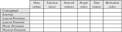
Formal connections between cells should be established. For example, we should be able to map (or forward engineer) a conceptual model to a logical model and then a physical model, or go back the other way {reverse engineering).
If the application uses separate models for the transient and persistent data, then object-relational mapping procedures are required to map between the two layers. Having a framework like this helps us to evaluate how well we are catering for different aspects of an information system.
Many other frameworks have been proposed in industry for architecting an information system. Four of these are now mentioned briefly. Further details on these approaches may be found in the references listed in the chapter notes.
The Object Management Group Model Driven Architecture (MDA) approach includes three levels: Computation Independent Model (CIM), Platform Independent Model (PIM), and Platform Specific Model (PSM). The CIM level is partly conceptual, the PIM level is logical, and the PSM level is physical.
The Open Group Architecture Framework (TOGAF) includes four levels or domains (Business, Application, Data, Technology) and provides a detailed Architecture Development Method (ADM) that may be tailored to an organization’s needs and employed to manage the execution of architecture planning activities.
The International Standards Organization (ISO) Standard Reference Model of Open Distributed Processing (RM-ODP) incorporates five viewpoints: Enterprise, Information, Computational, Engineering, and Technology (ISO 2000a,b).
The Framework of Information System Concepts (FRISCO) developed by an IFIP working group provides a taxonomy of concepts used in information systems work (Falkenberg et al. 1998). Although not widely adopted, the FRISCO report provides some useful insights into information system development.