
9.8. Mapping from ORM to UML
The UMLmap procedure in Table 9.3 provides basic guidelines for mapping ORM schemas to UML class diagrams. Selected entity types and value types map to object classes and data types, including attribute domains when associations are replaced by attributes. We now illustrate this procedure. As a preparatory move, step 1 binarizes any sets of exclusive binaries, as shown in Figure 9.55.
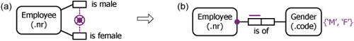
Figure 9.55. Step 1: replace any set of exclusive binaries by a binary fact type.
In step 2, we decide which object types to model as classes and which n: 1 and 1:1 ORM associations to remodel as attributes. Typically, entity types that play functional fact roles become classes. Functional binary (n:1 and 1:1) associations from an entity type A to a value type B, or to an entity type B about which you never want to record details, usually map to an attribute of A. If you have specified role names, these can usually be used as attribute names, with the object type name becoming the attribute’s domain name.
The mapping in Figure 9.56 illustrates several of these step 2 considerations, as well as step 6 (map ORM constraints to UML graphic constraints, textual constraints, or notes). The {P} and {Ul} annotations for preferred identifier and uniqueness are not standard UML. The value constraint on gender codes is captured using an enumeration type.
Figure 9.56. Step 2: map selected n:1 and 1:1 associations to attributes.

In rare cases, value types that are independent, play an explicit mandatory role, or play a functional fact role in an :n fact type map to classes. The example in Figure 9.57(a) deals with cases where we store title-gender restrictions (e.g., the title ‘Mr’ is restricted to the male gender). The example in Figure 9.57(b) uses a multivalued attribute to store all the genders applicable to a title (e.g., the title ‘Dr.’ applies to both male and female genders). The Title class gives fast access from title to applicable gender, but slow access from gender to title. As discussed earlier, multivalued attributes should be used sparingly.
Figure 9.57. Step 2: rare cases of value types mapping to classes.

In step 3 we map unaries to Boolean attributes or to subclasses. The example in Figure 9.58 assumes a closed world interpretation for the unary. With an open world approach, the isSmoker attribute is assigned a multiplicity of [0..1] and the {complete} constraint is removed from the subclassing. Open/closed world aspects are discussed in more detail in Chapter 10.
Figure 9.58. Step 3: map unaries to Boolean attributes or subclasses.

In step 4, the remaining fact types are mapped to associations. Any m:n associations should normally remain that way. In the example in Figure 9.59, the n: 1 fact type is retained as an association because it relates two entity types that become classes in the mapping. Even if the m:n association did not apply, we would normally retain Country as a class, since now or later we are likely to record details for it (e.g., country name).
Figure 9.59. Step 4: map remaining fact types to associations.

If an m:n association involves a value type (e.g., Employee has PhoneNr) instead of using a multivalued attribute, see if it is possible to transform the m:n association into multiple n:1 associations (e.g. Employee has PhoneNrl; Employee has PhoneNr2, etc.). Conceptual schema transformations like this are discussed in depth in Chapter 14.
If each object type in an n-ary fact type should map to a class (e.g., it plays other functional roles), then map the n-ary fact type to an n-ary association. Figure 9.60 provides an example.
Figure 9.60. Step 4: map some n-ary fact types to n-ary associations.

If an object type in a ternary fact type should not map to a class (typically an m:n:l uniqueness pattern with it outside the uniqueness constraint), then objectify the rest of the association as an association class and map its role as an attribute. Figure 9.61 shows an example.

Objectified associations map to association classes, as shown earlier in Figure 9.18. Some cases of coreference could be mapped into qualified associations, but mapping to separate attributes or associations supplemented by a textual composite uniqueness constraint offers a more general solution.
In step 5, the simplest constraints in ORM usually map in an obvious way to multiplicity constraints, as illustrated earlier. The more complex ORM constraints have no graphic counterpart in UML, so you need to record these separately in textual form. Table 9.4 summarizes the main correspondences. Join constraints are considered in the next chapter.
| ORM constraint | UML |
|---|---|
| Internal UC | Maximum multiplicity of 1, or (Un) |
| External UC | Qualified association or textual constraint |
| Simple mandatory | Minimum multiplicity of 1, or textual constraint |
| Inclusive-or | Textual constraint (unless within exclusive-or) |
| Frequency | Multiplicity or textual constraint |
| Value | Enumeration or textual constraint |
| Subset and Equality | Subset(s) or textual constraint |
| Exclusion | Textual constraint (unless within exclusive-or) |
| Ring constraints | Textual constraint |
| Join constraints | Textual constraint |
| Object cardinality | Class multiplicity |
In step 6, subtypes are mapped to subclasses, adding relevant subclassing constraints. Subtype definitions are handled with discriminators and/or textual constraints. For example, the ORM schema considered earlier in Figure 9.38 maps to the UML schema in Figure 9.37.
In step 7, we map derived and semi-derived fact types. The schemas in Figure 9.53 and Figure 9.54 provide simple examples.
With these hints, and the examples discussed earlier, you should now have enough background to do the mapping manually for yourself. The following short exercise will give you some practice at this. If you are keen on using UML for data modeling, you may wish to use UML to model some of the many modeling exercises in other chapters.
Exercise 9.8
Model the following application in UML. We suggest that you do an ORM model first, but that’s up to you. The universe of discourse is based on a simplified fragment of a database application used by an electrical utility to help manage the delivery of electricity to consumers in Australia. A line link is a section of an electrical feeder or mains power line that connects two adjacent nodes (e.g., power poles, pillar-boxes).
The figure shown illustrates a tiny part of the electrical power network. Here three power poles (also called telephone poles) carry power lines to supply electricity. The house is one of many receiving electricity from the power company.

The following output report provides an extract of sample data about line links. The link types listed are not exhaustive.
Line link Link type Linktype description Voltage (V) Current (A) Power (kW) Length (m) 33 OW open wire 11000 400 4400 200 40 UGC underground cable 11000 400 4400 150 55 ABC aerial bundled conductor 415 300 124.5 170 56 ABC aerial bundled conductor 240 200 48 180 The following report shows details about line links to help with fault detection and correction. Each power line link has a switch at both ends. The switches can be remotely toggled open (to break the circuit) or closed. Line status has only two values as shown.
Line link From node To node Status Start switch End switch 33 B D OK Closed Closed 40 D E OK Closed Open 55 F G Faulty Open Open 56 F G OK Closed Closed The following report extract lists details about nodes and any consumers serviced with electricity by those nodes. Only nodes with a transformer (i.e., nodes for which we record a transformer type) can service a consumer. A consumer may be serviced by many nodes and has exactly one, two, or three phases supplied (regardless of which node supplies the power). The transformer types shown here (PT = Pole Transformer, PMT = Pad-mounted transformer, GT = Ground Transformer) are not meant to be exhaustive. Codes of transformer types are stored but descriptions are not.
Note: In reality a consumer has only one node for normal service, and possibly other nodes for backup in the case of a fault—however, we ignore this refinement since its modeling requires subtypes, which we avoid in this simple exercise. Data models of electrical applications usually include many subtypes.
Node Nr fuses Transformer type Consumer serviced Nr phases supplied B 3 PT ? ? D 0 ? ? ? E 1 PMT 3001 2 3005 3 ... ... ... ... ... F 2 GT 5678 2 5700 1 ... ... ... ... ... G 2 GT 5678 2 ... ... ... ... ... The following report extract lists details about electrical faults suffered by consumers. Timestamps may be treated as a single value (including both date and time of day).
Consumer Fault type Reported Fixed Fault cause 3005 Dim lights 2006-04-29 09:30 2006-04-30 10:45 ? Dim lights 2007-07-12 17:25 ? Wires down 5678 Blackout 2006-04-30 11:20 2006-05-01 6:30 Lightning strike Cold water 2006-04-30 11:20 ? ? The following report extract indicates electrical energy consumption (in kilowatt hours) by consumers on a quarterly basis. Some consumers (e.g., recent ones) might not yet appear in the report. Although consumption can be derived from other data not shown here, assume that it is simply stored for this exercise.
Consumer Quarter Consumption (kW.h) Year QtrNr 3001 200 4 1622 6 1 1500 200 2 2001 7 ... ... 5678 200 2 2001 ... 7 ... ... ... 200 7 ... Specify a UML schema for this UoD, including constraints and derivation rules.
Suppose that in the model, Fault is an association class to objectify the association Consumer reported FaultType at Instant. Suggest a new identification scheme for Fault to improve the usability of the model.
Model the academic schema in Exercise 8.5, Question 2 in UML.