3.3. CSDP Step 1: From Examples to Elementary Facts
To specify what is required of an information system, we need to answer the question: What kinds of information do we want from the system? Clearly, any information to be output from the system must be stored in the system or be derivable by the system. Our first step is to begin with familiar examples of relevant information, and express these in terms of elementary facts. As a check on the quality of our work, we ask the following questions. Are the entities well identified? Can the facts be split into smaller ones without losing information? This constitutes step 1 of the conceptual schema design procedure.
|
CSDP step 1: Transform familiar examples into elementary facts. |
For process modeling, it helps to begin with examples of the processes to be carried out by the system. In 1987 such process examples were coined “use cases”, which nicely suggests cases of the system being used. UML recommends such use cases to drive the modeling process. Although process use cases help with designing process models, in practice the move from such use cases to data models is often somewhat arbitrary and frequently results in data models that need substantial reworking.
Business process modeling is part of the overall process of modeling a business domain. In practice, it is often helpful to begin with a high level view of the services to be provided by the system and then later refine these services into processes that describe how those services are provided. Since processes typically operate on data, however, we feel that a detailed description of those processes should wait until we have a clear understanding of the data. While the topic of business process modeling is the focus of a later chapter, our current and main concern is to ensure high fidelity data models.
If you want to get the data model right, start with examples of the data to be delivered by the system. By analogy with the UML term, we call these ”data use cases”, since they are cases of data being used. However this is just another name for the “familiar information examples” concept introduced to the ORM schema design procedure in the 1970s. If you ever do use UML’s process use cases to drive the modeling process, you should at least flesh them out with data samples before working on the class diagrams.
If we are modeling a business domain previously managed manually or by computer, information examples are readily available. If not, we work with the domain expert to provide examples. Three types of examples are output reports, input forms, and sample queries. These might appear as tables, forms, diagrams, or text. To verbalize such examples in terms of elementary facts, we need to understand what an elementary fact is.
To begin with, an elementary fact is a simple assertion, or atomic proposition, about the UoD. The word “fact” indicates that the assertion is taken to be true by users in that business domain. Here “taken to be true” has the sense of epistemic commitment—the business users are prepared to act as if they believed the assertion to be true. Whether the proposition is actually true is of no concern to the system. In everyday speech, facts are true statements about the real world. However, in computing terminology we resign ourselves to the fact(!) that it is possible to have false “facts” in the database (just as we use the word “statement” for things that aren’t really statements in languages like SQL).
We may think of the UoD as a set of objects playing roles. Elementary facts are assertions that particular objects play particular roles. The simplest kind of elementary fact asserts that a single object plays a given role. For example, consider a small domain in which people are identified by their first names. One fact about this domain might be:
Ann smokes.
Here we have one object (Ann) playing a role (being a smoker). Strictly, we should be more precise in identifying objects (e.g., expand “Ann” to “the person with firstname Ann‘”); but let’s tidy up later. With sentences like (1), the role played by the object is sometimes called a property of the object. Here an elementary fact asserts that a certain object has a certain property. This is also called a unary relationship, since only one role is involved. Usually however, a relationship involves at least two roles. For example:
Ann employs Bob.
Ann employs Ann.
In (2) Ann plays the role of employer and Bob plays the role of employee. In (3) Ann is self-employed and plays both roles. In general, an elementary fact asserts that a particular object has a property, or that one or more objects participate together in a relationship.
Here ”elementary” indicates the fact cannot be “split” into smaller units of information (with the same objects) that collectively provide the same information as the original. Elementary facts usually do not use logical connectives (e.g., not, and, or, if) or logical quantifiers (e.g., all, some). For example, sentences (4)-(9) are not elementary facts.
Ann smokes and Bob smokes.
Ann smokes or Bob smokes.
Ann does not smoke.
If Bob smokes then Bob is cancer prone.
All people who smoke are cancer prone.
If some person smokes then that person is cancer prone.
All of these sentences express information. Proposition (4) is a logical conjunction. It should be split into two elementary facts: Ann smokes; Bob smokes. Proposition (5) is a disjunction, (6) is a negation, and (7) is a conditional fact. Most database systems do not allow such information to be stored conveniently, and are incapable of making relevant inferences (e.g., deducing that Bob smokes from the combination of (5) and (6)). For most commercial applications, there is no need to store such information.
Often the absence of positive information (e.g., Ann smokes) is taken to imply the negative (Ann does not smoke): this is the usual “closed world” assumption. With an “open world” approach, negative information can be explicitly stored using negative predicates or status object types, in conjunction with suitable constraints. For example, the predicates “smokes” and “is a non-smoker” are mutually exclusive, and the fact type Person has SmokerStatus {‘S’, ‘NS’} requires the constraint that Each Person has at most one Smoker-Status. Sometimes the choice of whether to store positive or negative information depends on which occupies less space, and the borderline between positive and negative may become blurred (e.g., consider Person dislikes Food and Patient is allergic to Drug).
Universally quantified conditionals such as (8) and (9) may be catered for by subset constraints or derivation rules. Derivation rules can be specified readily in SQL (e.g., by means of a view), and are also easily coded in languages such as Prolog. For example: cancerProne(X) if person(X) and smokes(X).
Elementary facts assert that objects play roles. How are these objects and roles specified? For now, we consider only basic objects: these are either values or entities. A value is a constant that is self-identifying in the sense that when you see the constant written down in some context you always know what is being referred to. As a result, values can be referenced directly, without needing to identify them with a description.
For now, it is sufficient to recognize two kinds of value: character string and number. Character strings are shown inside quotes (e.g., ‘USA’). Numbers are denoted without quotes, typically using the usual Hindu-Arabic decimal notation (e.g., 37 or 5.2). Numbers are abstract objects denoted by character strings called numerals. For example, the number 37 is denoted by the numeral ‘37’. We assume that any information system supports strings and numbers as built-in data types. Values are displayed textually, but are internally represented by bit-strings.
Conceptually, an entity (e.g., a particular person or car) is referenced in an information system by means of a definite description. For example, kangaroos hop about on an entity identified as “the Country named ‘Australia‘”. Entities may also be called “described objects”. Unlike values, some, indeed most, entities can change with time. An entity may be a tangible object (e.g., the City named ‘Paris’) or an abstract object (e.g., the Course with code ‘CS114’). We consider both entities and values to be objects that exist in the UoD. Object-oriented approaches instead use the term “object” in a more restrictive sense that approximates our use of “entity”. Usually we want to talk about just the entities, but to reference them we make use of values. Sometimes we want to talk about the values themselves. Consider the following sentences:
Australia has six states.
”Australia” has nine letters.
This is a case of what logicians call the use/mention distinction. In (10) the word “Australia” is used to reference an entity. In (11) the word “Australia” is simply mentioned, and refers to itself. In written English language, quotes resolve this distinction. In everyday communication, entities are often referred to by a proper name (e.g., “Bill Clinton”) or by some definite description (e.g., “the previous president of the USA”, or “the president named ‘Bill Clinton‘”). Proper names work if we know what the name refers to from the context of utterance. For example, in (10) you probably took “Australia” to refer to the country named “Australia”. However, the sentence itself does not tell you this. Perhaps (10) was about a dog named “Australia” who has six moods (sleepy, playful, hungry, etc.).
Since humans may misinterpret, and information systems lack any creativity to add context, we play it safe by demanding that entities be clearly identified by definite descriptions. To begin with, the description must specify the kind of entity being referred to: the entity type. A type is the set of all possible instances. Each entity is an instance of a particular entity type (e.g., Person, Country). For a given UoD, the entity type Person is the set of all people we might want to talk about during the lifetime of the information system. Note that some authors use the word “entity” for “entity type”. We sometimes expand “entity” to “entity instance” to avoid any confusion. Consider the sentence
Lee is located in 10B.
This could be talking about a horse located in a stable, or a computer in a room, and so on. By stating the entity types involved, (13) avoids this kind of referential ambiguity. Names of object types are highlighted here by starting them with a capital letter.
The Patient ‘Lee’ is located in the Ward ‘10B’.
Recall the old joke: ”Question: Did you hear about the man with the wooden leg named ‘Smith’ ? Answer: No—What was the name of his other leg?” Here the responder mistook ‘Smith’ to refer to an entity of type WoodenLeg rather than of type Man. Sometimes, even stating the entity type fails to fully clarify things. Consider the sentence:
The Patient ‘Lee’ has a Temperature of 37.
Now imagine that the UoD contains two patients named “Lee Jones” and “Mary Lee”. There is more than one person to which the label “Lee” might apply. Worse still, there may be some confusion about the units being used to state the temperature: 37 degrees Celsius is normal bodily temperature, but 37 degrees Fahrenheit is close to freezing! We resolve this ambiguity by including the reference mode (i.e., the manner in which the value refers to the entity). Compare the following two sentences:
The Patient with surname ‘Lee’ has a Temperature of 37 Celsius.
The Patient with firstname ‘Lee’ has a Temperature of 37 Fahrenheit.
A common way to avoid potential confusion caused by overlap of first names and surnames is to demand that fuller names be used (e.g., “Lee Jones”, “Mary Lee”). In some cases, however, even these names may not be unique, and another naming convention must be employed (e.g., PatientNr). To avoid confusing “No.” with the word “No”, we’ll use “Nr” or “#” to abbreviate “Number”. Most entity designators have three components:
Entity type (e.g., Patient, Temperature)
Reference mode (e.g., surname, Celsius)
Value (e.g., ‘Lee’, 37)
This is the simplest kind of entity designation scheme. We’ll restrict our discussion of reference schemes to this simple case for quite some time. Composite identification schemes are considered later.
Now that we know how to specify objects, how do we specify the roles they play? We use logical predicates. In logic, a predicate is basically a declarative sentence with object holes in it. To complete the sentence, the object holes or placeholders are filled in by object terms. Each object term refers to a single object in the UoD. Object terms are also called singular terms, or object designators. For us, values are designated by lexical constants (sometimes preceded by the value-type name), and entities are designated by definite descriptions that relate values to entities. Consider the following sentence:
The Person with firstname ‘Ann’ smokes.
Here the object term is “The Person with firstname ‘Ann‘”. For discussion purposes, the predicate identifier is shown here in italics. The predicate may be shown by itself as “... smokes”, using an ellipsis “...” as a placeholder or “object hole” for an object instance. This is a unary predicate, or sentence with one object hole in it. It may also be called a property, or a unary relationship type.
A binary predicate is a sentence with two object holes. Most predicates in information models are binary. Consider this example:
The Person with firstname ‘Ann’ employs the Person with firstname ‘Bob’.
Here the predicate may be shown by itself as “... employs ...”, with two object holes. Notice that the order in which the objects are placed here is important. For example, even if it is true that Ann employs Bob, it may be false that Bob employs Ann.
A ternary predicate is a sentence with three object holes. For instance, the fact that Terry worked in the Computer Science Department for 10 years involves the predicate “... worked in ... for ...”.
An n-ary predicate is a sentence with n object holes (n > 0). Since the order is significant, a filled-in n-ary predicate is associated with a sequence of n object terms, not necessarily distinct. The value of n is the arity, or degree, of the predicate. Predicates of arity ≥ 2 are polyadic. An elementary fact asserts a proposition of the form:
Ro1...on
where R is a predicate of arity n, and o1...on are n object-terms, not necessarily distinct (as in predicate logic). Moreover, with respect to the UoD, the proposition must not be expressible as a conjunction of simpler propositions.
For naturalness, we write predicates in mixfix (or distfix) form, where the terms may be mixed in with the predicate. For example, the following ternary fact uses the predicate “... moved to ... during ...”.
The Scientist with surname ‘Einstein’ moved to the Country with code ‘USA’ during the Year 1933 CE.
Step 1 of the CSDP involves translating relevant information examples into sentences like this. As a simple example, consider the output report of Table 3.1. Try now to express the information in the first row in the form of elementary facts. To help with this, use the telephone heuristic. Imagine you have to convey the information over the telephone to someone. In performing this visual to auditory transformation, you should fully specify each entity in terms of its entity type, reference mode, and value, and also include the predicate reading.
| Designer | Language |
|---|---|
| Wirth | Pascal |
| Kay | Smalltalk |
| Wirth | Modula-2 |
In reports like this, the column headings and table names or captions often give a clue as to the object types and predicates. The column entries provide the values. Here is one way of translating row 1 as an elementary fact:
The Person with surname ‘Wirth’ designed the Language named ‘Pascal’.
Notice that the entity types and reference modes appear as nouns, and the predicate as a verb phrase. This is fairly typical. In translating row 1 into the elementary fact (20), we read the row from left to right. If instead we read it from right to left, we might say:
The Language named ‘Pascal’ was designed by the Person with surname ‘Wirth’.
In reversing the order of the terms, we also reversed the predicate. We speak of “was designed by” as the inverse of the predicate “designed”. Although semantically we might regard sentences (20) and (21) as expressing the same fact, syntactically they are different. Most logicians would describe this as a case of two different sentences expressing the same proposition. Linguists like to describe this situation by saying the two sentences have different surface structures but the same deep structure.
For example, one linguistic analysis might portray the deep structure sentence as comprising a verb phrase (Design) and various noun phrases (the object terms) each of which relates to the verb in a different case (e.g., agentive for Wirth and objective for Pascal), together with a modality (past tense). Different viewpoints exist as to the “correct” way to portray deep structures (e.g., what primitives to select), and the task of translation to deep structures is often complex. In practice, most information systems can be designed without delving further into such issues.
It is important not to treat sentences like (20) and (21) as different, unrelated facts. Our approach with binary fact types is to choose one primary way of stating the predicate, but optionally allow the inverse reading to be shown as well. For example:
The Person with surname ‘Wirth’ designed I was designed by the Language named ‘Pascal’.
Here the predicate on the left of the slash “/” is used for the left-to-right reading (20). The predicate on the right of the slash is used for the inverse reading (21). The slash visually suggests jumping over the other predicate when reading left-to-right, and jumping under the other predicate when reading right-to-left. Having different ways to talk about a fact type can help communication, and can improve constraint specification. For example, the constraint verbalization “Each Language was designed by some Person” is preferable to the equivalent “For each Language, some Person designed that Language”.,N-ary fact types have many possible orderings, but typically only one is displayed.
Now consider Table 3.2. This is a bit harder to verbalize since the columns don’t have separate names. Assume that Adam and Jim are males and that Eve and Mary are females. Try to verbalize the top row in terms of elementary facts before reading on.
| Married couples | |
|---|---|
| Terry | Norma |
| Tony | Gwen |
Perhaps you verbalized this as in (23). For completeness, the inverse is included.
The Person with firstname ‘Terry’ is married to I is married to the Person with firstname ‘Norma’.
Notice that the forward predicate is the same as the inverse. This is an example of a symmetric relationship. Such relationships create special problems (as discussed in a later chapter). To help avoid such problems, at the conceptual level no asserted predicate should be the same as its inverse.
You can always rephrase the fact to ensure this. For example, (24) does this by highlighting the different roles played by each partner.
The Person with firstname ‘Terry’ is husband of I is wife of the Person with firstname ‘Norma’.
Now consider Table 3.3. This is like Table 3.1 but with an extra column added. Try to express the information on the first row in terms of elementary facts before reading on.
| Designer | Language | Year |
|---|---|---|
| Wirth | Pascal | 1971 |
| Kay | Smalltalk | 1972 |
| Wirth | Modula-2 | 1979 |
We might at first consider expressing this information as sentence (25), using the ternary predicate “... designed ... in ...”. Do you see any problems with this?
The Person with surname ‘Wirth’ designed the Language named ‘Pascal’ in the Year 1971 CE.
Recall that an elementary fact must be simple or irreducible. It cannot be split into two or more simpler facts in the context of the UoD. The appearance of the word “and” in a sentence usually indicates that the sentence may be split into simpler facts. Here there is no “and”, but “common sense” tells us that the fact can be split into the following two elementary facts with no information loss:
The Person with surname ‘Wirth’ designed the Language named ‘Pascal’.
The Language named ‘Pascal’ was designed in the Year 1971 CE.
Here “no information loss” means that if we know (26) and (27) then we also know (25). The phrase “common sense” hides some formal ideas. In order to split (25) into (26) and (27) we probably relied on our implicit understanding that each language was designed in only one year. This constraint holds if we interpret “was designed in” to mean “had its design completed in”. Let us agree with this interpretation.
If instead we meant “had work done on its design in” then a language may be designed in many years. In this case, we could still justify the split if each language had only one designer, or at least the same set of designers for each year. However, this might not be true. For example, if we include UML as a language, it had different designers in different years. This illustrates the need to be clear about the meaning of our wording and to strive for sample data that illustrate just what is possible.
The ORM method encourages the use of informative terms for object types and predicates. However, sometimes it is difficult to think of a term that captures the precise meaning and is also conveniently short. In such cases, if the meaning of an object type name or predicate reading could be misinterpreted, it is important to add a descriptive comment to clarify its meaning. Although such comments are often suppressed on ORM diagrams, modern ORM tools allow them to be captured and displayed elsewhere.
Later CSDP steps add some formal checks to detect violations of elementarily, so if our “common sense” fails us in step 1, we will normally see this error at a later stage. For now though, let’s work with our intuitions. Suppose we split the ternary into the two binaries: Person designed Language; Person completed design in Year. Would this be acceptable? As an exercise, use the table’s population to show that this kind of split would actually lose information.
After plenty of practice at step 1, you may wish to write the elementary facts down in abbreviated form. To start with, you can drop words such as “the” and “with” where they introduce object types and reference modes. Reference modes are placed in parentheses after the object types. A dot before the reference mode name indicates that the object type name is prepended to it in the underlying value type name. For example, Language(.name) and Country(.name) have different underlying value types LanguageName and Country-Name. A colon after the reference mode name, e.g., Height(cm:), indicates unit-based measurement. The next section discusses the various kinds of reference mode in more detail.
You may shorten some identifiers for object types, reference modes, and predicates so long as the shorter readings are still meaningful. In English, start the name of object types with a capital letter. Start the name of reference modes with a small letter, unless capitals have significance (e.g., “CE”). For example, facts (26) and (27) may be set out more concisely as (26a) and (27a).
26a. Person (surname) ‘Wirth’ designed Language (.name) ‘Pascal’.
27a. Language (.name) ‘Pascal’ was designed in Year (CE) 1971.
If the reference schemes for entity types are declared earlier, they may be omitted in setting out the facts. For example, (26) and (27) may be specified as:
Reference schemes;Person(surname); Language(.name); Year(CE)
Facts.      Person ‘Wirth’ designed Language ‘Pascal’.
               Language ‘Pascal’ was designed in Year 1971.
Even more conveniently, a fact type may be displayed in diagram form (see next section), and fact instances may be entered into the relevant fact table simply by entering values.
The task of defining a formal grammar sufficient to capture any sentence expressed in natural language is daunting, partly because of the many ways in which objects may be referenced. For example, consider the sentence: “The next person to step on my toe will cop it”. Some artificial intelligence research is directed toward sorting out the semantics in sentences like this.
Fortunately for us, such sentences don’t appear in database tables, where simple value-based schemes are used to reference objects. ORM is capable of formally capturing the relevant semantics of any fact that can be represented in a database table. Structured object-terms and predicates provide the logical deep structure, independent of the natural language (English, Japanese, etc.) used to express the fact. By supporting ordered, mixfix predicates ORM enables this deep structure to be expressed in a surface structure in harmony with the ordered, mixfix nature of natural language. For example, consider Figure 3.1.
Figure 3.1. The same fact in English and Japanese.
| EmployeeNr | Department |
|---|---|
| 37 | Sales |
| Jugyo in | Ka |
|---|---|
| 37 | Eigyo |
Here the two tables convey the same fact in different languages. The fact may be expressed in English as (28) and in Japanese as (29). For discussion purposes, the reference modes are underlined and the predicates are italicized.
Jugyo in jugyo in bango ‘37’ wa ‘Eigyo’ to iu namae no Ka ni shozoku suru.
These may be parsed into the structures shown in 28a and 29a, with the predicates again italicized. The sentences have the same deep structure. The infix predicate “... works in ...” corresponds to the mixfix predicate “... wa ... ni shozoku sum”.
28a. Employee (.nr) ‘37’ works in Department (.name) ‘Sales’.
29a. Jugyo in (.bango) ‘37’ wa Ka (.namae) ‘Eigyo’ ni shozoku sum.
Now consider the two output reports in Figure 3.2. Try to verbalize their top row in terms of one or more elementary facts. The data in Figure 3.2(a) are real, while the data in Figure 3.2(b) are fictitious but possible. You may assume that the following reference schemes are predeclared: Politician(.name); Country(.code); and Year(CE).
Figure 3.2. Two reports about politicians.
|
Although there are in principle infinitely many possible interpretations of the data, you can probably guess the intended meaning. We may read off the information for Figure 3.2 (a) and Figure 3.2(b), respectively, as shown in the following two facts.
30. The Politician ‘George W. Bush’ was born in the Country ‘US’ in the Year 1946.
31. The Politician ‘George W Bush’ visited the Country ‘GB’ in the Year 2003.
While these facts do provide a correct interpretation of the meaning of the data on the top rows, only one of these facts is elementary. Which is it?
Fact 30 is not elementary, since it may be split into the following facts without loss of information.
32. The Politician ‘George W. Bush’ was born in the Country ‘US’.
33. The Politician ‘George W. Bush’ was born in the Year 1946.
Connecting two sentences by “and” forms a logical conjunction of the two sentences. Intuitively, fact 30 is equivalent to the conjunction of facts 32 and 33, so fact 30 is split-table (nonelementary). Formally, this is because of a uniqueness constraint on the politician column—each politician was born in only one country and in only one year. We discuss such constraints in a later chapter and provide rules and heuristics to help determine whether a given fact is elementary. For now, however, let’s just use our intuitions.
Fact 31 is elementary, because you cannot treat it as a conjunction of simpler facts without losing information. For example, if we told you that George W. Bush visited the United Kingdom (the country with country code ‘GB’) and that he travelled overseas in 2003, it does not follow that he visited the United Kingdom in that year.
In some cases, a ternary that is not splittable into two facts may be split into three facts. Here we might try to split fact 31 into the above two facts as well as the third fact that the United Kingdom was visited in 2003. However even these three facts don’t guarantee that George W. Bush visited the United Kingdom in 2003.
Formally, the structural difference between reports (a) and (b) is their uniqueness constraint pattern. In report (a) the first column values must be unique (not duplicated). In report (b) only the whole rows must be unique (entries for single columns or any column pair may be duplicated). The next chapter discusses such patterns in detail.
As another example, consider the report shown in Table 3.4. Try step 1 yourself on this table before reading on.
Table 3.4. A report storing facts about lecturers.

One tricky feature of this table is the final column. Entries in this column are sets of degrees. Phrase your sentences to include only one degree at a time. Step 1 applied to the first row results in four facts that may be set out as follows.
34. The Lecturer with name ‘Adams JB’ was born in the Year 1946 CE.
35. The Lecturer with name Adams JB’ has the Age 42 years.
36. The Lecturer with name Adams JB’ holds the Degree with code ‘BSc’.
37. The Lecturer with name Adams JB’ holds the Degree with code ‘PhD’.
Here the entity types and reference modes are Lecturer (.name), Year (CE), Age (y:), and Degree (.code). There are three fact types: Lecturer was born in Year; Lecturer has Age; and Lecturer holds Degree. The entity types Year and Age are semantically different. Year involves a starting point in time, whereas Age is merely a duration of time (in this case, measured in years).
A more difficult example is shown next in Table 3.5. This is an extract of a report on tutorial groups. Perform step 1 yourself on this before reading the following discussion.
Verbalization of an example involves interpretation, so it is important that the kind of example is familiar to us or the domain expert who is assisting us with step 1. Since domain experts often lack technical expertise in modeling, we should not expect them to do all of step 1 themselves. It is sufficient if they verbalize the information correctly in their own terms. This is step 1a: verbalize the information (perhaps informally).
As modelers, we often need to refine their verbalization by ensuring that the facts are elementary and that the objects are well identified. This is step lb: verbalize the information as elementary facts. For example, a domain expert might perform step la by verbalizing the information on the top row of this report as:
Tute group A meets at 3 p.m. Monday in Room CS-718.
Student 302156 belongs to group A and is named ‘Bloggs FB’.
We might then perform step lb by refining these informal sentences into the following four elementary sentences:
38. The TuteGroup with code ‘A’ meets at the Time with dhcode ‘Mon 3 p.m.’.
39. The TuteGroup with code ‘A’ meets in the Room with roomNr ‘CS-718’.
40. The Student with studentNr 302156 belongs to the TuteGroup with code ‘A’.
41. The Student with studentNr 302156 has the StudentName ‘Bloggs FB’.
Many features in this example rely on interpretation. For instance, we assumed that StudentNr and StudentName refer to students and that a student number and student name on the same row refer to the same student. We also filled in the associations as “meets at”, “meets in”, “belongs to”, and “has”. The report itself does not tell us this. We use our background familiarity with the situation to make such assumptions.
Decisions were also made about entity types and reference schemes. For example, we treated Time as an entity type referenced by a day-hour-code rather than introducing Day and Hour entity types. A similar comment applies to Room and StudentName.
StudentNr was chosen rather than StudentName to identify Student. The report helps here since StudentNr appears first (on the left) and ‘Bloggs FB’ appears with two different student numbers, suggesting that more than one student may have the same name. However, we are still making assumptions (e.g., that students have only one student number, or that students belong to only one group).
Another major assumption is that each tutorial group meets only once a week. We need to know this to justify using separate facts for the time and room (rather than verbalizing this as: TuteGroup meets at Time in Room). Of course the fact that group A is not repeated in the report helps us with this decision, but this still assumes the sample is representative in this regard.
Since interpretation is always involved in the initial step, if we are not familiar with the example we should resolve any doubts by asking a domain expert, using examples familiar to them. Although we as modelers might be expert in expressing ourselves at a formal, type level, not all domain experts can do this. By working with examples familiar to the subject matter experts, we can tap their implicit understanding of the UoD without forcing them to abstract and express, perhaps incorrectly, the structure we seek.
Sentence (41) expresses a relationship between an entity (a student) and a value (a name). When verbalizing facts, the value type is stated just before the value (e.g., Stu-dentName ‘Bloggs FB’). Unlike entity terms, value terms have no reference scheme.
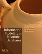
With many reports it is sometimes useful to draw a connection between the relevant fields as we verbalize the corresponding fact. For example, we might add links between the columns of Table 3.5 as in Figure 3.3. This informal summary of the fact types helps us see if some connections have been missed.
Figure 3.3. Drawing connections for the verbalized relationships.
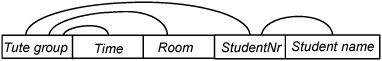
In addition to tables, forms are a common source of information examples. Consider the input form shown in Figure 3.4. Forms are used more often for input than output, but may be used for both (e.g., the personnel forms considered in the previous chapter).
Figure 3.4. An input form for collecting tutorial preferences.
Suppose students studying the subject CS114 use the form in Figure 3.4 to indicate up to three preferences regarding which tutorial time is most suitable for them. This form is used to help decide which students are assigned to which groups, and which groups are eventually used. If this information is to be taken into account in determining tutorial allocations, it must be stored.
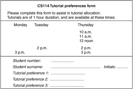
Let’s assume that the previous output report (Table 3.5) shows the tutorial allocations for CSl 14, made after all the student preferences are considered. The preference input form lacks some of the information needed for the allocation report. For example, it does not show how groups are assigned to rooms and times. This helps prevent students from entering wrong data (they enter the times they prefer directly rather than indirectly through associated group codes) and allows flexibility in offering many tutorials at the same time. To perform step 1 here, we first fill out the form with some examples, as shown in Figure 3.5.
Figure 3.5. The tutorial preference form populated with sample data.

These facts may now be verbalized as Student(.nr) 302156 has Surname ‘Jones‘; Student 302156 has Initials ‘ES‘; Student 302156 has first preference at Time(.dhCode) ‘Mon 3 p.m.‘; Student 302156 has second preference at Time ‘Thurs 11 a.m.’.
Taken individually, the output report and the input form reveal only partially the kinds of information needed for the system. In combination however, they might be enough for us to arrive at the UoD structure. If so, the pair of examples is said to be significant.
In general, a set of examples is significant or adequate with respect to a specific UoD only if it illustrates all the relevant sorts of information and constraints. With complex UoDs, significant example sets are rare. With our current example, if a student can be allocated to only one group then Table 3.5 is significant in this respect.
However, if more than one group can be held at the same time, Table 3.5 is not significant in this other respect. A further row is needed to show this possibility (e.g., a row indicating that group B2 meets at Tuesday 2 p.m.).
When extracting facts from information examples, we need to decide which aspects should be modeled. This helps determine the scope of the UoD. A useful heuristic is to ask the question: Which parts may take on different values? Look again at the input form in Figure 3.5. The header section contains information that we may or may not wish to model. The first item we see is “CS114”. Is it possible to have other values in place of it, within our overall application? If the only subject of interest is CS114, then the answer is “no”. However if we wish to cater for other subjects as well, we might require another form with a different value here (e.g., “CS 183”). In this case we need to introduce Subject (or some equivalent term) as an object type within our UoD.
Different universities may use different terms for a unit of study. Instead of our “Subject”, terms such as “Course” or “Unit” might be used. If the domain experts all prefer the same term, use that. If different people use different terms for the same concept, get them to agree upon a standard term, and also note any synonyms in use.
Returning to the header of our preferences form in Figure 3.5, we see the word “Tutorial”. Could this change (e.g., to “Lecture”)? If we wish to capture preferences for lectures as well as tutorials, the answer is “yes”, and we could model this as data. But let’s assume that this is not the case. The rest of the form header contains other information (e.g., duration of tutorials) but let’s assume this doesn’t need to be modeled.
The middle section of the form contains information about the tutorial times. If our UoD has only one subject (CS 114), we could model this information as unary facts (e.g., Time ‘Mon 3 p.m.’ is available’). If we need to cater for other subjects as well, then we need to treat the “CS 114” at the top of the form as data, and hence verbalize the schedule as binary facts (e.g., Subject ‘CS114’ has a tutorial slot at Time ‘Mon 3 p.m.’). A completed tutorial preference form for a different subject is shown in Figure 3.6.
Figure 3.6. A completed tutorial preference form for a different subject.

Here the layout of the five weekdays into columns makes it more obvious that the times are to be treated as data. The first fact from this section reads: Subject ‘CS 183’ has a tutorial slot at Time ‘Tues 2 p.m.’.
If you reformat the structure of the earlier CS114 example (Figure 3.5) to agree with this structure and place the two forms side by side, you can see what aspects are to be modeled as data by looking at what data changes between the two forms (subject code, times, student details).
In this larger UoD, assuming that students may enrol in many subjects, the facts about student preferences now need to take the subject into account. Instead of binaries, the preference facts are now verbalized as ternaries. For example: Student 302156 has first tutorial preference for Subject ‘CS114’ at Time ‘Mon 3 p.m.‘; Student 211780 has third tutorial preference for Subject ‘CS183’ at Time ‘Tues 3 p.m.’. Tutorial allocations would also need to indicate the relevant subject (e.g., Table 3.5 would need a header showing the subject). Tutorial groups would then need a composite reference scheme including both the subject code and the group code. For example, the first fact from the CS114-headed version of Table 3.5 would now read as: TuteGroup ‘A’ of Subject ‘CS114’ meets at Time ‘Mon 3 p.m.’. Composite reference schemes are discussed in detail later in the book.
It is seen later that no set of examples can be significant with respect to derivation rules or subtype definitions. In such cases the use of a domain expert is essential. With the current domain, we made no mention of the rules used to arrive at the tutorial allocations. If in addition to storing information about preferences and allocations, the information system has to compute the allocations in a nearly optimal way, respecting preferences and other practical constraints (e.g., size of groups), the design of the derivation rules becomes the challenging aspect of the schema. While this can be automated, an alternative is to divide the task between the human expert and the system. High level languages facilitate such cooperative solutions.
Often, information examples used for verbalization in step 1 apply to the way the business or application domain currently works. From these examples we can build the as-is model to reflect the current practice (as it is now). Some changes may also be needed to expand or improve the way the business operates. For example, we might start with separate applications to administer tutorials for just one subject and then realize it would be better to integrate these into a single application capable of handling all the subjects (as discussed earlier). By including examples of the new data requirements, we are then able to build the to-be model, which reflects the way we want the business to be in the future. A proper understanding of the as-is model is a great assistance in designing the to-be model. As you gain more experience as a modeler, you will be able to draw upon lessons learned from prior modeling projects to help spot ways to improve things on future projects. Modeling is not just a science. It’s an art as well, and that makes it more fun.
A comprehensive set of output reports (covering intermediate stages) may include all the information on input forms. Output reports tend to be easier to interpret, especially if the input forms have been poorly designed. Care is needed in the design of the input forms to make them clear and simple for users.
Information can appear in many ways. Apart from various tables and forms, information may be expressed graphically in various diagrams, charts, maps, and graphs. Harris (1996) discusses several hundred different ways of presenting information graphically. Regardless of how it’s presented, information can always be verbalized as facts. Because practice helps with verbalization skills, we’ve included many varied examples in the book to prepare you for performing step 1 in practical situations.
As a simple graphical example, Figure 3.7 might be used to display information about nonstop flight connections provided by a particular airline, with the arrowheads indicating the direction of the flights. As an exercise, perform step 1 for this graph before reading on.
Figure 3.7. A graph showing nonstop flight connections between cities.

Now let’s see how well you performed. There is only one entity type: City (.name). There is also only one fact type: City has a flight to City. For instance, the arrow from Chicago to Seattle may be verbalized as: City ‘Chicago’ has a flight to City ‘Seattle’. The “to” in the predicate is important, since it conveys direction and avoids the symmetry problem with the earlier marriage example.
If this was an as-is model, and we wanted also to talk about the flight connections (e.g., state their duration) or to include many airlines, we should add flight numbers to the arrows on the graph. This to-be model leads to a different verbalization, which you might like to try for yourself. A later exercise returns to this example.
In practice, it is usually possible for a city to have more than one airport, so that connections apply directly between airports rather than cities. Airports are identified by airport codes (e.g. ‘JFK’ and ‘LGA’ respectively denote John F. Kennedy and LaGuardia airports which service New York).
Airports can service a city without being located in that city. For example, Newark airport (EWR) located in New Jersey also services New York, and Sea-Tac airport (SEA) located between Seattle and Tacoma services Seattle. We need to determine which specific kinds of fact are of interest in the business domain and verbalize them precisely (e.g., Airport services City is a different fact type from Airport is located in City).
By now you may have some sense of the power of verbalizing examples in terms of elementary facts. No matter what kind of example you start with, if you or an assistant understands the example then you should be able to express the information in simple facts. This does require practice at the technique, but this is fun anyway—isn’t it?
If you can’t do step 1, there is little point in proceeding with the design—either you don’t understand the UoD or you can’t communicate it clearly.
Although it might sound hard to believe, if you have performed step 1 properly, you have completed the hardest part of the conceptual schema design procedure. The remaining steps consist of diagramming and constraining the fact types. Apart from the problem of detecting unusual constraints and derivation rules, once you learn the techniques you can often carry out those steps almost automatically. With step 1, however, you always need to draw upon your interpretation skills.