
Using AutoTrack
AutoTrack is a feature that was first introduced with AutoCAD 2000. It’s actually made up of two features. The first, Object Snap Tracking, was originally introduced with Release 14, and is enhanced in this new release. The other, Polar Tracking, was new in AutoCAD 2000. Together, these two tracking features are collectively called AutoTrack.
AutoTrack creates temporary alignment paths: dashed construction lines that appear onscreen to help you identify pick points. When your cursor properly aligns with the preset Polar or Object Snap Tracking angle, the dashed line appears, and your cursor is constrained to it. This simplifies the identification of potential pick points.
The difference between Polar Tracking and Object Snap Tracking is this: Polar Tracking creates alignment paths for points you have already set, whereas Object Snap Tracking creates alignment paths based on acquired Osnaps. In other words, Polar Tracking displays alignment paths for the last point selected, and functions independently of Osnaps. In contrast, Object Snap Tracking displays alignment paths only if you use Osnaps, and move the cursor over an Osnap marker to acquire it.
This section describes both Object Snap tracking and Polar Tracking, and provides a simple exercise that shows you how to use these two powerful features.
Object Snap Tracking
Object Snap Tracking was introduced in AutoCAD Release 14, and was originally called Tracking. As with many new AutoCAD features, this feature was first introduced in AutoCAD LT where it has been very popular. Although not an object snap in the strict sense, Object Snap Tracking is used with standard Osnaps to enhance your ability to find points relative to another object’s geometry.
You can use Object Snap Tracking whenever AutoCAD prompts for a point. If you try to use Object Snap Tracking when no command is currently running, AutoCAD displays an error message.
When you start Object Snap Tracking by acquiring an Osnap point, AutoCAD displays either orthogonal alignments, or preset polar angle alignments. You control whether Object Snap Tracking uses orthogonal or polar alignments from the Polar Tracking tab on the Drafting Settings dialog box (refer to Figure 6.25). By choosing the Track Orthogonally Only option in the Object Snap Tracking Settings area, Object Snap Tracking displays only orthogonal alignment paths. If the Track Using All Polar Angle Settings option is selected, alignment paths are displayed for all angles listed in the Polar Angle Settings area, also found on the Polar Tracking tab.
You acquire an Osnap by moving the cursor over an Osnap marker. When prompted to select a point during a command, if Object Snap Tracking is enabled and you move your cursor over an Osnap marker, a small cross appears in the marker, indicating that the point is acquired. Then, as you move the cursor away from the point, the orthogonal or polar alignment paths appear, and your cursor is constrained to them as you move along the paths. To clear an acquired point, move the cursor back over the Osnap marker.
Note
It is important to understand that you acquire an AutoTrack point by simply moving your cursor over the Osnap marker. Do not pick the point. Just move the cursor over the marker; AutoCAD will acquire the point automatically and display a small plus (+) sign in the center of the Osnap marker.
To remove the small symbol from an acquired point, move the cursor back over the small plus (+) sign. AutoCAD removes the symbol, and the point is “un-acquired.”
Tip
You can set a temporary tracking point without using Osnap markers. By typing TT at any point prompt, AutoCAD prompts for a temporary OTRACK point. After a point is selected, AutoCAD places a small + at the point, indicating that the tracking point is set. To remove the temporary tracking point, move the cursor over the small +.
Polar Tracking
Polar Tracking is the perfect complement to Object Snap Tracking. When enabled, Polar Tracking alignment paths appear on screen as you move away from the point you have already set. However, unlike Object Snap Tracking, you do not need to acquire a point to display the polar angle alignment paths. If Polar Tracking is enabled, the alignment paths automatically appear as you move away from the last point, and prepare to pick the next.
Polar Tracking is discussed in detail earlier in this chapter in the section “The Polar Tracking Feature.”
In the following exercise, you use the AutoTrack features.
Exercise 6.9 Using AutoTrack’s Object Snap Tracking and Polar Tracking Features
1. |
Open the drawing 06DWG04.dwg. The drawing appears, showing two parallel line segments, three units apart. |
2. |
From the Tools menu, select Drafting Settings. The Drafting Settings dialog box appears. |
3. |
Select the Object Snap tab. Be sure the Endpoint and Midpoint Object Snap modes are selected, and that all other options are cleared, including the Object Snap On and Object Snap Tracking On, as shown in Figure 6.35. Figure 6.35. The proper Object Snap settings for this exercise.
|
4. |
From the Drafting Settings dialog box, select the Polar Tracking tab. Be sure the Polar Tracking On option is cleared, and that the Track Using All Polar Angle Settings and Absolute options are selected. |
5. |
In the Polar Angle Settings area, from the Increment Angle drop-down list, select 30.0, as shown in Figure 6.36. Figure 6.36. The proper Polar Tracking settings for this exercise.
|
6. |
From the Drafting Settings dialog box, select the Snap and Grid tab. Be sure the Snap On and Grid On options are cleared. |
7. |
In the Snap Type & Style area, select Polar Snap. The Polar Spacing area activates, and the Snap area grays. |
8. |
In the Polar Spacing area, set the polar distance to 0.5, as shown in Figure 6.37, and click OK. Figure 6.37. The proper Snap and Grid settings for this exercise.
|
9. |
From the status bar at the bottom of the screen, click to depress, if needed, the SNAP, POLAR, and OSNAP buttons to activate the Snap grid, Polar Tracking, and Object Snap features. |
10. |
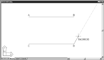
From the Draw menu, select Line, then pick the endpoint of the line at location D. |
11. |
Move your cursor away from the endpoint. Notice as you move your cursor around that dashed alignment paths appear at 30-degree increments. This occurs because you set the increment angle to 30.0, and selected the Track Using All Polar Angle Settings option (refer to Figure 6.36). |
12. |
Move your cursor up and to the right of the endpoint, until the 60-degree alignment path appears. Drag your cursor along the 60-degree alignment path. Notice that the cursor is constrained to the path, and that it snaps at 0.5 unit increments. This occurs because you set the polar distance to 0.5, and chose the Polar Snap option (refer to Figure 6.37). |
13. |
Pick the line’s endpoint when the AutoTrackToolTip reads Polar: 1.0000<60, as shown in Figure 6.38, then press Enter to end the LINE command. Figure 6.38. The Polar Tracking feature displays alignment paths in the designated angle increments.
|
14. |
From the status bar at the bottom of the screen, click the OTRACK button to activate the Object Snap Tracking feature. Then click the SNAP and POLAR buttons to turn off the Snap grid and Polar Tracking features. |
15. |
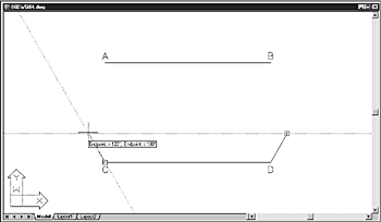
From the Draw menu, click Line, then pick the endpoint of the line at C. Move your cursor over the endpoint at C, and when the Endpoint Osnap marker appears, move cursor into the marker until a small cross (or plus sign) appears. When the small + appears, Object Snap Tracking is activated for this marker. (Do not pick the endpoint.) |
16. |
Next, move your cursor to the endpoint of the first line you created. When the Endpoint Osnap marker appears, move the cursor into the marker until a small + appears. When the small + appears, Object Snap Tracking is activated for this marker. (Do not pick the endpoint.) |
17. |
Move your cursor to the left along the Object Snap Tracking alignment path, toward the endpoint at C. As you near the endpoint at C, Object Snap Tracking alignment paths appear for its marker. |
18. |
Continue moving your cursor toward the left until the AutoTrack ToolTip reads Endpoint:<120, Endpoint:<180. Pick the point, as shown in Figure 6.39, then press Enter to end the LINE command. You will continue to use this drawing in the next exercise. Figure 6.39. The Object Snap Tracking feature displays alignment paths for acquired Osnap markers.
|


As you just experienced, AutoTrack’s Object Snap Tracking and Polar Tracking features can help you pick points by displaying temporary alignment paths. Remember that Object Snap Tracking relies on Osnaps, and sets alignment paths only when an Osnap marker is acquired. In contrast, Polar Tracking functions independently of Osnaps, and displays alignment paths during a command as you move your cursor away from the last point set.