
Working with Lineweights
AutoCAD 2000 introduced a new feature called lineweights, which allows you to affect the appearance of objects. Just as linetypes make similar objects, such as lines and polylines, stand apart from each other, so, too, lineweights can make individual objects more easily identifiable.
In previous releases of AutoCAD, you could assign widths to polylines, which perform a function similar to that of lineweights. The problem was that you could assign widths only to polylines—not lines, not circles, and certainly not text. Another problem with assigning widths to polylines was its unfriendliness. If a polyline was already created with the wrong width, you had to edit it to change the width. More importantly, unless you had access to specialized AutoLISP routines, you could edit the width of polylines only one at a time. In contrast, lineweights allow you to assign widths to a wide range of objects, including text, and assign the widths individually, globally, and even by layer using AutoCAD’s Layer Properties Manager.
In this section, you learn about assigning lineweights to objects. More importantly, you learn how the appearance of lineweights is affected under different circumstances.
Assigning Lineweights
The topic of assigning lineweights is much the same as discussed for assigning linetypes: You can do it either globally through the Layer Properties Manager, or individually through the Object Properties toolbar. And, as in the argument presented in the “Assigning Linetypes” section, it is strongly suggested that you avoid assigning lineweights individually because doing so makes editing the lineweights of many objects a daunting, unproductive task.
If you are new to AutoCAD, you will probably find yourself tempted to pick just a single object and reassign its lineweight individually. After all, it is a very easy thing to do. You just pick the object, choose the desired lineweight from the pull-down list on the Object Properties toolbar, and you’re done. But chances are, you will regret setting the lineweight individually as your drawing grows more and more complex, containing hundreds, or perhaps thousands, of objects. It is much better in the long run to consistently assign a lineweight globally using the Layer Properties Manager, even if it means creating a new layer for just that one object and assigning that layer the desired lineweight. By doing so, you create an understanding not only with yourself, but with anyone else who may work on your drawing, that lineweights are always edited using the Layer Properties Manager. This understanding provides a consistent pattern for everyone to use when editing objects.
For more information on controlling lineweights globally through the Layer Properties Manager, and individually through the Object Properties toolbar, refer to Chapter 4 in the section “The Linetype and Lineweight Properties.”
Understanding Lineweight Behavior
Lineweights display differently under different circumstances. For example, while working in model space, lineweights are displayed by a certain number of pixels. Consequently, as you zoom in closer to a line, the number of pixels displaying the lineweight does not change. If a lineweight in model space is displayed as four pixels, it’s always displayed as four pixels, no matter how far you zoom out or how close you zoom in. Therefore, the lineweight always appears as the same width. In contrast, while working in paper space (now referred to as a layout since AutoCAD 2000), lineweights are displayed at their true width. If a lineweight of 0.25 mm is assigned, then AutoCAD displays the line as 0.25 mm wide in the layout. Therefore, as you zoom in closer, the line appears wider. In other words, the lineweights of objects drawn in a layout display in real-world units. There is another feature of lineweights that you can control. When in model space, if you assign lineweights to objects, you can alter their apparent scale so they appear thinner or wider visually. This apparent scale does not affect lineweight widths when viewed in a layout or when plotted. Therefore, you can dynamically alter lineweights in model space to make viewing objects easier, without adversely affecting how they plot.
In the next exercise, you learn how lineweights act in model space and in a layout, and how to alter their apparent scale in model space.
Exercise 5.4 Understanding Lineweight Behavior
1. |
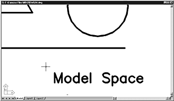
Open the drawing 05DWG04. The drawing opens a layout that displays objects drawn in both model space and paper space, as shown in Figure 5.20. The circle, triangle, line, and the text Model Space are drawn in model space. The text Paper Space is drawn in paper space in the Layout tab. The solid rectangle is the edge of the floating viewport, and the dashed rectangle represents the plotting limits. Figure 5.20. The drawing in a layout view has several objects drawn in model space, including the text Model Space. The text Paper Space is drawn in paper space.
|
2. |
From the View menu, choose Zoom, Window, then pick a zoom window that surrounds the two text objects, as shown in Figure 5.21. Notice that the lineweights of both text strings appear equal in width. More importantly, they also appear wider. This occurs because you are viewing the layout in paper space mode. Therefore, AutoCAD displays the lineweights at their real-world size. As you zoom in closer, the lines appear wider. Figure 5.21. In paper space, the lineweights of the two text objects appear wider as you zoom in closer.
|
3. | |
4. |
Choose the Model tab (located near the bottom-left of the screen). AutoCAD switches to model space, and the model space objects display, as shown in Figure 5.22. (Although the objects in the figure appear with a heavy lineweight, your drawing may look different.) Figure 5.22. The model space view of the objects.
|
5. |
From the View menu, choose Zoom, Extents. AutoCAD zooms in closer to the objects, a shown in Figure 5.23. Notice that the lineweights of the objects did not get wider as you zoomed in. This occurs because in model space, the number of pixels that are used to display a lineweight does not change as you zoom in closer. Figure 5.23. The lineweights of the model space objects do not get wider as you zoom in closer.
|
6. |
From the Format menu, choose Lineweight. The Lineweight Settings dialog box appears, as shown in Figure 5.24. Figure 5.24. The Lineweights Settings dialog box allows you to control various features of lineweights.
|
7. |
Pick and drag the Adjust Display Scale button along its slide bar all the way to the right, then click OK. The lineweights will update to appear wider onscreen, as shown in Figure 5.25. Figure 5.25. The Adjust Display Scale feature affects how wide lineweights appear onscreen in model space.
|
8. |
Choose the Layout 1 tab. AutoCAD switches to Layout 1, and displays objects in paper space, as shown in Figure 5.26. Notice that the lineweights are not as wide as they were in model space. Once again, this occurs because objects in the layout appear at their real-world scale. AutoCAD therefore ignores the Adjust Display Scale setting while in paper space and when plotting. Figure 5.26. The Adjust Display Scale feature does not affect how wide lineweights appear onscreen in paper space layouts.
|


One last feature you should be aware of is how to control whether lineweights display onscreen. You can turn off lineweight display by clicking the LWT button in the AutoCAD 2002 status bar. By clicking this button, you toggle lineweights off and on. However, this button does not affect how lineweights plot.