Setting Up Drafting Settings
AutoCAD allows you to control a number of drafting settings that help you work efficiently, and make your drawings more accurate. These settings consist of a series of system variables that you can set at the command prompt. Additionally, you can easily access them through the Drafting Settings dialog box (formerly the Drawing Aids dialog box.) The Drafting Settings dialog box is shown in Figure 6.23, and is accessed through the Tools menu by selecting Drafting Settings. This dialog box is also available from the Command: prompt by typing DDRMODES .
Figure 6.23. The Drafting Settings dialog box.
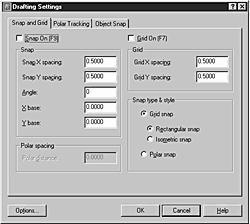
The Drafting Settings dialog box consists of three tabs. The Snap and Grid tab controls snap and grid settings, including the X and Y increment spacing, the X axis angle, and the X and Y base point. The Polar Tracking tab, introduced in AutoCAD 2000, controls polar tracking settings. It controls features that function similar to AutoCAD’s ORTHO mode, but allows you to apply the features to angles in any increment. The Object Snap tab (formerly the Osnap Settings dialog box) controls running object snaps, which are object snaps that are always turned on.
This section reviews the system variables accessed through the Drafting Settings dialog box, and their related commands.
Understanding Snap and Grid Options
The Snap and Grid tab on the Drafting Settings dialog box is made up of four major sections. These sections control how AutoCAD’s snap feature functions, and how its grid displays. By understanding how these features function, you make drawing objects with AutoCAD easier and intuitive.
Snap
Options in the Drafting Settings dialog box control the Snap grid (refer to Figure 6.22). When the Snap grid is enabled (when a check mark, or X, appears in the Snap On check box), the movement of the crosshairs cursor is restricted to incremental displacements across a grid of invisible “snap” points. This enables you to snap to and select points on this grid with a high degree of precision. You can enter both Snap X and Snap Y spacing for your snap grid by typing in the input boxes in this section. The other options—Snap Angle, X Base, and Y Base—control the angle at which the grid is oriented with respect to the current UCS and the origin’s coordinates of the snap’s grid.
The Snap grid settings can also be controlled at the command prompt with the SNAP command. You can toggle on and off the Snap feature by pressing the F9 key, by pressing Ctrl+B, or by clicking the SNAP button on the status bar.
By carefully selecting the spacing of the Snap grid, you can usually make the picking of points much easier because you bypass the need to enter points at the keyboard.
Tip
When entering values in X and Y spacing text edit boxes in both the Grid and Snap sections of the Drafting Settings dialog box, typing a value in the X Spacing box and pressing Enter will automatically transfer the value to the Y Spacing box. Because I usually want the X and Y values of both of these settings equal, this shortcut eliminates the need to type anything in the Y boxes.
Grid
In addition to a grid of invisible snap points, you can apply a grid of visible points to the drawing area. This visible drawing aid is simply called Grid. The controls found in the Grid area determine the location of the grid’s visible points.
When the Grid On option is selected, grid points are made visible with the spacing specified by the values (in drawing units) that you type into the Grid X Spacing and Grid Y Spacing edit boxes (refer to Figure 6.23).
It is common to link the spacing of the grid of visible points (the Grid) to the grid of invisible snap points. To establish this link, the X and Y spacing of the Grid points is set to 0. AutoCAD then uses the X and Y spacing of the Snap points and automatically applies these to the visible Grid. You can, of course, override this 1:1 relationship by explicitly entering values other than 0 for the Grid spacing. Keep in mind that regardless of the setting(s) of the Grid points, the origin and angle of the Grid is always kept the same as the origin and angle of the Snap points.
You can also control the visible Grid with the GRID command, and toggle on and off the Grid by pressing the F7 key, by pressing Ctrl+G, or by clicking the GRID button on the mode status bar.
Tip
The Grid control section of the Drafting Settings dialog box largely duplicates functions available through the basic GRID command. Using the GRID command at the command prompt, however, offers an option: Grid spacing (X). Specifying a value followed by an “X” sets the Grid spacing to the specified value times the Snap interval. I often like to set my Snap spacing at a fraction—perhaps 1/4—of my Grid value. By using the “X” feature of the spacing setting available with the GRID command, this relationship between Grid and Snap remains in effect no matter how often I change the Grid setting.
Snap Type & Style
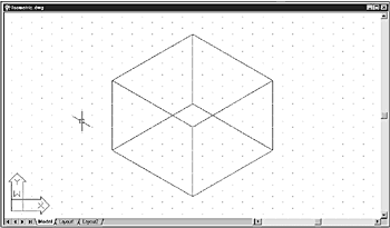
The Snap Type & Style area controls whether rectangular, isometric, or polar snaps and grids are used. By selecting the Grid Snap option button, you can choose between the Rectangular and Isometric snap and grid modes. The Rectangular mode is AutoCAD’s standard snap and grid mode. The Isometric mode allows you to easily draw isometric views of objects, such as the cube shown in Figure 6.24. Notice the alignment and skew of the cursor when Isometric mode is selected.
Figure 6.24. The Isometric snap mode is used to draw isometric views of objects.
Tip
The isometric view shown in Figure 6.24 is displayed in Isoplane Left mode. You can cycle through three modes—Isoplane Left, Isoplane Top, and Isoplane Right—by pressing F5 or Ctrl+E. As you cycle through each mode, AutoCAD realigns the cursor to match the selected mode.
The Polar Snap option causes the cursor to snap along polar alignment angles set on the Polar Tracking tab relative to the starting polar tracking point. The snap increment is determined by Polar Distance setting in the Polar Spacing area, discussed in the next section.
The Polar Tracking Feature
In AutoCAD 2000, a feature was introduced called Polar Tracking, which provides the ability to constrain cursor movement into predefined polar alignment angles. This feature functions similar to ORTHO mode, but instead of constraining cursor movement horizontally and vertically in 90-degree increments, you can set the polar alignment increments to any angle.
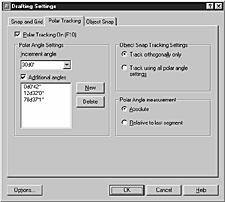
In the Polar Angle Settings area, you can select the desired polar alignment angle from a predefined list containing commonly used angles. The angles are selected from the Increment Angle drop-down list, which contains angles measured in the following degrees: 90, 45, 30, 22 1/2, 18, 15, 10, and 5. Additionally, you can set up to 10 user-defined angles. By selecting the Additional Angles option, then clicking the New button, AutoCAD allows you to add your own polar alignment angles in the Additional Angles list as shown in Figure 6.25. To remove user-defined angles, select the angle from the list, then click the Delete button.
Figure 6.25. The Polar Tracking tab allows you to define your own polar alignment angles, as displayed in the list box.
Note
When you select an angle from the Increment Angle drop-down list, AutoCAD constrains cursor movement every time the cursor crosses an angle increment (the cursor “snaps” to the angle increment). In contrast, a user-defined angle entered in the Additional Angles list only constrains cursor movement when the cursor crosses the listed angle(s). Therefore, using the Increment Angle and Additional Angles options shown in Figure 6.25, the cursor constrains its movement every 30 degrees (30, 60, 90, 120, and so on). Using these options also constrains cursor movement at 0 degrees, 00 minutes, 42 seconds; at 12 degrees, 32 minutes, 00 seconds; and at 78 degrees, 37 minutes, 01 seconds.
Tip
You can temporarily constrain cursor movement to any angle not listed in the Polar Tracking tab by using angle overrides. For example, to constrain cursor movement to 33 degrees during a command, when prompted to specify the next point, type <33 , and AutoCAD will temporarily constrain the cursor for the next point to 33 degrees.
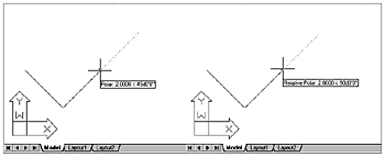
The Polar Angle measurement area determines whether polar tracking alignment angles are measured absolutely or relatively. Angles measured absolutely are determined relative to the current UCS. Angles measured relatively are determined relative to the last point selected. For example, in Figure 6.26, with the Polar Angle measurement option set to Absolute, the image on the left displays the cursor’s polar position at 45 degrees, as measured from the current UCS. In contrast, with the Polar Angle measurement option set to Relative to last segment, the image on the right displays the cursor’s relative polar position at 90 degrees, as measured from the last line segment.
Figure 6.26. You can track polar alignments absolutely, based on the current UCS, or relatively, based on the last point selected.
The Object Snap Tracking Settings area allows you to set tracking to orthogonal, or to all the polar settings displayed in the Polar Angle Settings area. The Track Orthogonally Only option is the original option first introduced with tracking in Release 14. The Track Using All Polar Angle Settings option was introduced in the AutoCAD 2000 series, and constrains cursor movement to the predefined polar alignment angles. These options are discussed in detail later in this chapter.
Object Snapping
No matter how carefully you set your Snap interval or how often you change that interval, it is highly unlikely that all the points in your drawings will conveniently fall on these predefined snap points. This becomes increasingly true as your drawing becomes populated with various objects that themselves have important geometric features, such as endpoints, centers, and tangent points, to which you will want to relate other drawing objects.
Most modern CAD applications, including AutoCAD, therefore, provide some means of identifying these geometric points. These tools simplify the construction of new geometry, and enable you to draw created objects more accurately, and to consistently maintain the results with far more precision than is possible in traditional manual drafting. In AutoCAD, this capability is called object snapping, and is also referred to as Object Snap, or Osnap. In AutoCAD, these modes consist of a set of tools that permit accurate geometric construction.
Osnaps are used to directly and easily identify key points either on or in relation to your drawing objects. Figure 6.27 shows the Object Snap toolbar and the pop-up Cursor menu.
Figure 6.27. The Object Snap toolbar and the pop-up Cursor menu.

The Osnap toolbar and the Cursor menu contain the same Osnap modes presented in essentially the same order. You can display or activate the pop-up Cursor menu by pressing Shift and right-clicking, commonly called Shift+right-click, or simply pressing Shift+Enter because the right mouse button serves as an Enter button. If you use a three-button mouse, the middle button can usually be configured to “pop up” the Cursor menu.
The Osnap modes are also represented on the Standard toolbar by a “fly-out” toolbar. Figure 6.28 displays both the Osnap toolbar and the Osnap fly-out. As shown, the Osnap toolbar can be displayed in a vertical format and placed or moved to a convenient position in your drawing area. 6.27 6.27 shows the same toolbar displayed horizontally.
Figure 6.28. The Object Snap toolbar and fly-out.

Note
To resize any toolbar, move your cursor to an edge of the toolbar. When the cursor is in the proper position to resize the toolbar, it turns into a double-headed arrow. Then just click and drag to resize the toolbar as desired.
Tip
Depending on personal preference and the type of drafting you are involved with, you can use the Osnap toolbar (in either a horizontal or vertical format, or even a more compact rectangular arrangement), the Osnap fly-out from the Standard toolbar, or the pop-up Cursor menu. The fly-out has the advantage of being present only during Osnap selections, whereas the Osnap toolbar can be moved around and resized; the Cursor pop-up menu, on the other hand, requires very little cursor movement. I almost always use the cursor menu because it is the quickest for me.
Note
The position and size of a toolbar can be saved to a Profile, which can be recalled later to restore preferred toolbar layouts. For detailed information, refer to Chapter 3, “Controlling the AutoCAD 2002 Drawing Environment,” in the section “Saving the Options to a Profile.”
Osnap Modes
AutoCAD has 16 Object Snap modes, including the two new modes introduced in AutoCAD 2000. Table 6.1 gives a description of each mode.
Running Osnap Toggle and Osnap Override
Running Osnap Toggle and Osnap Override are two useful AutoCAD features first introduced in Release 14. They are important adjuncts to the overall operation of object snaps and are therefore discussed here.
Object Snap Toggle
Running toggle is an Osnap enhancement that enables you to toggle off any running (continuing) Osnap prior to selecting a point without losing the running Osnap settings. This feature is accessed by clicking the OSNAP button on the mode status bar at the bottom of AutoCAD’s screen. If this button is selected when no running Osnaps are set, the Object Snap tab on the Drafting Settings dialog box is displayed, giving you the opportunity to set a running Osnap.
Object Snap Override
AutoCAD 2002 provides an option that enables you to explicitly enter coordinate data that has priority over any running Osnaps that may be in effect. This enhances direct coordinate entry and you can be certain that such entries have precedence over any other settings. To temporarily override a running Osnap, simply choose an Object Snap using any method described previously in the Object Snapping section. AutoCAD uses the selected Snap override for the next pick only, then reverts to running Osnaps.
AutoSnap
AutoSnap is an important feature in AutoCAD that was first introduced with Release 14. With AutoSnap, you can visually preview snap point candidates before picking a point. Depending on how you have AutoSnap features set, AutoSnap will display a Snap Tip placard similar to the toolbar’s ToolTip feature. Also, a marker distinctive to each Osnap mode can be displayed in the color of your choice, making for easy identification of the snap location and snap type. You can also enable a “magnet” feature that snaps the marker into place much like the action of AutoCAD’s Grips feature.
In the following exercise, you use some of AutoCAD’s Osnap modes and the three methods of invoking them. In addition, you will see how the AutoSnap feature makes looking for and confirming Osnap points an unambiguous, efficient means of picking Osnap points.
Exercise 6.8 Bisecting an Angle Using Object Snaps with AutoSnap
1. |
Open the drawing 06DWG03.dwg. The drawing appears, showing two line segments whose endpoints touch, creating an angle. If the Object Snap toolbar is not visible, proceed with steps 2 and 3. |
2. |
Right-click any toolbar button. The available toolbars appear on the pop-up Cursor menu, as shown in Figure 6.29. Figure 6.29. The available toolbars appear on the cursor menu.
|
3. |
Select Object Snap from the Cursor menu. Note that the Object Snap toolbar appears. |
4. |
From the Tools menu, select Options to display the Options dialog box, then select the Drafting tab. Ensure that the Marker, Magnet, and Display AutoSnap ToolTip features are all selected, and that the Display AutoSnap Aperture Box is cleared, as shown in 6.30 6.30 . Click OK to close the dialog box. Figure 6.30. The Drafting tab on the Options dialog box controls AutoSnap settings.
|
5. |
From the Draw menu, select Arc, Center, Start, End. You see the following prompt: Specify start point of arc or [CEnter]: _c Specify center point of arc: |
6. |
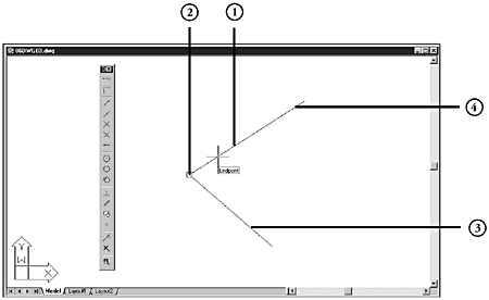
Click the Snap to Endpoint tool from the displayed Osnap toolbar. Then move and rest the screen cursor to a point near Figure 6.31. The AutoSnap feature identifies the line’s endpoint.
|
7. |
With the Endpoint Snap marker still displayed, pick a point near |
8. |
At the Specify start point of arc: prompt, click and hold the Osnap flyout on the Standard toolbar (refer to Figure 6.28), select the Snap to Nearest Tool, and release the pick button. Move the cursor near the lower line at |
9. |
Pick near |
10. |
Pick the upper line near Figure 6.32. Bisecting an angle using Osnaps.
|
11. |
Type L
and press Enter at the command prompt. At the Specify first point: prompt, type endp
and press Enter. Note the appearance of the Endpoint AutoSnap marker as you approach |
12. |
Click at |
13. |
At the next Specify next point or [Undo]: prompt, press Enter to end the LINE command. The bisector line is drawn, as shown in Figure 6.32. |
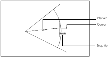
As seen in the preceding exercise, the use of Osnaps and the AutoSnap feature gives a definite, unambiguous indication of the geometry to which you are snapping. Even in crowded areas of a drawing, such as shown in Figure 6.33, positive identification of which point is the current snap target is possible.
Figure 6.33. AutoSnap provides positive identification of target geometry.
AutoSnap also supports a feature that enables stepping through the object snap points of objects lying within the target aperture when it is enabled. The Tab key is used to cycle from the closest to the furthest Osnap point from the center of the aperture box. The target geometry is highlighted to further aid in identification. This highlighting feature is shown in Figure 6.34, where the midpoints of two objects lie very close together and both fall within the Osnap aperture box. Repeated pressing of the Tab key cycles among the objects, highlighting the target geometry so that you can snap to the correct object’s midpoint.
Figure 6.34. In crowded areas, AutoSnap’s cycling feature highlights target geometry.

