From and Apparent Intersection Osnaps
Much like the Object Snap Tracking feature, the “auxiliary” Osnaps From and Apparent Intersection supply data points that stand in some relationship to points on drawing objects. The From object snap establishes a temporary reference point as a basis for specifying subsequent points. The From object snap is normally used in combination with other object snaps and relative coordinates. For example, at a prompt for the center point of an arc, you could type From Endp , select a line, and then type @4,5 to locate a point four units to the right and five units up from the endpoint of the selected line. The center of the arc would then be located at this point.
Apparent Intersection snaps to the apparent intersection of two objects that might or might not actually intersect in 3D space. In 2D drafting, Apparent Intersection is usually involved with the projected intersection of two line elements.
The following exercise demonstrates both the From and Apparent Intersection Osnaps as you center a line at a distance from the apparent intersection of two lines.
Exercise 6.10 Drawing a Line Using the From and Apparent Intersection Osnaps
1. |
Continue from the previous exercise, or open the drawing 06DWG05. |
2. |
From the status bar at the bottom of the screen, click the OTRACK and OSNAP buttons to turn off the Object Snap Tracking and Object Snap features. |
3. |
From the Draw menu, select Line. AutoCAD starts the LINE command. |
4. |
At the Specify first point: prompt, Shift+right-click to display the Cursor menu, then select From. |
5. |
At the Base point: prompt, Shift+right-click to display the Cursor menu, then select Midpoint. |
6. |
Pick the midpoint of line CD. |
7. |
At the Offset: prompt, type the relative coordinate @1.5,1
, then press Enter. This establishes the starting point of the line. |
8. |
At the Specify next point or [Undo]: prompt, Shift+right-click to display the Cursor menu, then choose Apparent Intersection. The Apparent Intersection snap requires selecting two different objects. After these objects are selected, AutoCAD determines the “apparent” intersection point of the two objects. |
9. |
At the Of: prompt, move your cursor to the line AB, near the endpoint at B. Notice the appearance of the Apparent Intersection AutoSnap marker, as shown in Figure 6.40. This line represents the first object. Figure 6.40. The Apparent Intersection Osnap marker displays.
|
10. |
Pick the line near B. AutoCAD now prompts for the other object. |
11. |
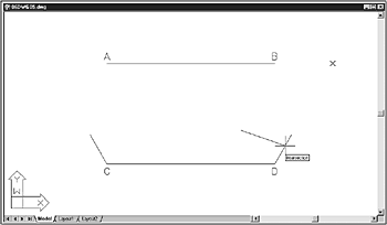
Move your cursor to the angled line extending up from point D. When you move your cursor over the line, AutoCAD displays the Intersection marker at the point the two objects “apparently” intersect, as shown in Figure 6.41. Figure 6.41. AutoCAD displays the Intersection marker at the point the two objects “apparently” intersect.
|
12. |
Pick the line. AutoCAD places the end of the line segment at the apparent intersection. |
13. |
Press Enter to end the LINE command. Leave this drawing open for the following exercise. |
The From and Apparent Intersection snap features provide tools that allow you to snap to points where no objects exist. With these tools, you set the first point of a line by offsetting it from the midpoint of an existing line, and snap the other end of the line to the apparent intersection of the two objects.


