
Assigning Linetypes
Assigning a linetype to an object is a straightforward process, and can be accomplished by one of two methods. You can assign linetypes globally, through AutoCAD’s Layer Properties Manager, or you can assign linetypes individually, from the Object Properties toolbar. Both methods are easy to use, and accomplish the same thing: assigning a new linetype to an object.
However, although both methods accomplish the same thing, one method definitely has an advantage over the other. By applying a linetype to a layer in the Layer Properties Manager dialog box, you control the appearance of all objects on that layer. This means you can instantly reapply a new linetype to hundreds of objects with a few simple clicks of your pointing device and change the linetype setting for a given layer.
In contrast, although assigning linetypes to objects individually does allow you to control their individual appearances, the process of individually changing the linetypes for dozens, or even hundreds, of objects can require tremendous amounts of editing time. Therefore, it is often best to avoid setting linetypes individually, and use the Layer Properties Manager to control a layer’s linetype assignment.
Tip
Always set the object linetype creation mode to ByLayer in the Objects Properties toolbar. This ensures all new object linetypes are controlled through the Layer Properties Manager, which provides a single point of control for modifying object linetypes.
For more information on controlling linetypes globally through the Layer Properties Manager, and individually through the Object Properties toolbar, refer to Chapter 4, “Organizing a Drawing with Layers,” in the section “The Linetype and Lineweight Properties.”
Loading Linetypes
In Chapter 4, in the section “The Linetype and Lineweight Properties,” you work through an exercise that shows how easy it is to assign linetypes to objects. In one of the exercise’s steps, you assign a linetype globally using the Layer Properties Manager. You select the desired linetype from the Select Linetype dialog box, shown in Figure 5.1.
Figure 5.1. The Select Linetype dialog box allows you to choose a layer’s linetype.

You will notice that there are not a lot of linetypes to choose from in the Select Linetype dialog box. However, AutoCAD 2002 is installed with dozens of predefined linetypes that you can use. You simply need to load them into your drawing.
In the following exercise, you learn how to load linetypes into the current drawing.
Exercise 5.1 Loading Linetypes into the Current Drawing
1. |
Open the drawing 05DWG01. The drawing displays a single dashed green line. |
2. |
From the Objects Properties toolbar, choose the Layers button (the second button from the left). The Layer Properties Manager dialog box displays. |
3. |
From the Existing Gas Line layer, under the Linetype column, choose the DASHED linetype. The Select Linetype dialog box appears, as shown in Figure 5.1. |
4. |
From the Select Linetype dialog box, click the Load button. The Load or Reload Linetypes dialog box appears. |
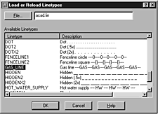
5. |
From the Load or Reload Linetypes dialog box, scroll down the list of available linetypes, and choose the GAS_LINE linetype, as shown in Figure 5.2. Figure 5.2. You can choose from a variety of predefined linetypes in the Load or Reload Linetypes dialog box.
|
6. |
Click OK. The Select Linetype dialog box appears, and the GAS_LINE linetype appears in the Loaded Linetypes list, as shown in Figure 5.3. Figure 5.3. The newly loaded GAS_LINE linetype appears in the Loaded Linetypes list and can now be assigned to a layer.
Notice in the Loaded Linetypes list that the DASHED linetype is still highlighted. When you click OK, the currently highlighted linetype is assigned to the Existing Gas Line layer. Therefore, to assign the newly loaded GAS_LINE linetype to the Existing Gas Line layer, the GAS_LINE linetype must be highlighted. |
7. |
Select the GAS_LINE linetype, then click OK. AutoCAD assigns the newly loaded GAS_LINE linetype to the Existing Gas Line layer, as shown in Figure 5.4 The. Figure 5.4 The. newly loaded GAS_LINE linetype is assigned to the Existing Gas Line layer.
|
8. |
Click OK. AutoCAD redraws the line using the GAS_LINE linetype, as shown in Figure 5.5. Figure 5.5. AutoCAD redraws the line using the GAS_LINE linetype.
|
9. |
You may close the drawing without saving the changes. |


By using the Load or Reload Linetypes dialog box, you can assign a wide range of linetypes to layers or to objects. But assigning a linetype is only half the solution to displaying objects with linetypes. The other half is to apply the proper linetype scale. In the next section you learn about the Linetype Scale Factor.
Working with the Linetype Scale Factor
The ability to assign a linetype to an object is very useful for representing different things in your drawing. By assigning a linetype, you help viewers more clearly understand the meaning of different objects. But assigning a linetype to an object, either globally or individually, is only half of the necessary solution to making your drawings easier to understand with linetypes. The other half of the solution is assigning the linetype a scale factor.
For the most part, a linetype is simply a series of repeated dashes and spaces. The lengths of the dashes and spaces are initially defined by the linetype’s description. However, the definition only specifies how many units long a dash or a space is. Depending on the scale of your drawing, the linetype may not be visible because the dashes and spaces appear too close together or too far apart. To compensate, AutoCAD allows you to assign a linetype scale factor to your drawing.
The linetype scale factor multiplies the current linetype style by the desired factor. As with linetypes, linetype scale factors can be assigned globally or individually. Unlike linetypes, however, you cannot assign a global linetype scale factor ByLayer using the Layer Properties Manager. When you set the linetype scale factor, it immediately affects all linetypes, no matter which layer they are on.
You change the linetype scale factor globally using the Linetype Manager dialog box, accessed by choosing Linetype from the Format menu. By clicking the Show Details button, you display the linetype details shown in Figure 5.6.
Figure 5.6. The Linetype Manager dialog box allows you to change the linetype scale factor.
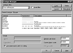
To change the global linetype scale, enter a new value in the Global Scale Factor text box. After this value is entered, and you click OK, AutoCAD immediately assigns the global scale factor to the display of all linetypes.
To assign a linetype scale factor individually to new objects, enter the desired linetype scale in the Current Object Scale text box. Don’t be confused by the title of this particular text box. When you use this text box to define a linetype scale, you are actually applying it to all new objects, not the currently selected object.
Although it may be useful to assign an individual linetype scale to new objects, it’s also possible to edit the linetype scale of existing objects. To do so, click the Properties button on the Standard toolbar, shown in Figure 5.7. Next, select the object(s) whose linetype scale factor you wish to change. Finally, enter the new linetype scale factor to apply to the objects in the Object Properties Manager dialog box as shown in Figure 5.8, then press Enter. AutoCAD assigns the new linetype scale factor individually to the selected objects. For more information about using the Object Properties Manager dialog box to assign new values to selected objects, see Chapter 11, “Advanced Geometry Editing.”
Figure 5.7. The Properties dialog box is accessed from the Properties button on the Standard toolbar.

Figure 5.8. The Properties dialog box allows you to change many values for selected objects, including their individual linetype scale factor.

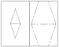
The final tool for controlling the linetype scale factor controls how linetypes appear in Layout viewports. This tool is necessary because AutoCAD allows you to create as many viewports in your Layout tab as you need to display your drawing. More importantly, you can apply a different zoom factor to each viewport. As a result, if one viewport is zoomed in close to an object, and another is zoomed out, the linetype will display differently in each viewport. Figure 5.9 illustrates two viewports that show the same object; each viewport is zoomed at a different scale. Notice the object’s dashed lines in the left viewport appear much smaller than in the viewport on the right. This is the effect when the Use Paper Space Units for Scaling feature is cleared (when there’s no check in the box). With this feature cleared, the dashed lines display proportionally to their zoom factor.
Figure 5.9. The dashed lines of the same object appear different in each paper space viewport with the Use Paper Space Units for Scaling feature cleared.
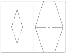
In contrast, review the same drawing with the Use Paper Space Units for Scaling feature selected, shown in Figure 5.10. Notice that the length of the dashes and the spaces are the same in both viewports. This is the effect the Use Paper Space Units for Scaling feature has on linetypes. Either method for scaling linetypes is acceptable. Whether the feature is selected or cleared depends on your needs.
Figure 5.10. The dashed lines of the same object appear identical in each paper space viewport with the Use Paper Space Units for Scaling feature selected.
There is one other property you should be aware of when dealing with linetypes and polylines, called linetype generation. Polylines are made up of a series of lines and arcs, connected at their endpoints by vertexes. When a linetype is assigned to a polyline, AutoCAD will either generate the linetype as one continuous line, or will generate the linetype anew at each vertex. In Figure 5.11, the polyline at the top has its linetype generated at each vertex, whereas the polyline at the bottom has its linetype generated as one continuous line. Once again, either method is acceptable, and the method you use depends on your needs, but most prefer to see their linetypes applied equally along the entire object.
Figure 5.11. The Linetype Generation property affects how linetypes appear when assigned to polylines. The property is disabled on the polyline at the top.

Tip
The Linetype Generation property can be enabled or disabled using the Properties dialog box.