
Linear sketch patterns allow us to pattern sketch entities in a linear direction. The following sketch shows us how we can define linear patterns in SOLIDWORKS sketching:

In the preceding sketch, the shaded circle is the base circle, while the other ones are additions to be made with the pattern command. The annotations in writing are the parameters that we need in order to communicate a pattern with SOLIDWORKS sketching. Each of the annotations is repeated twice, one for the X-axis and one of the Y-axis. They are as follows:
- Axes: The X-axis and Y-axis represent the direction in which our pattern is implemented.
- Total number of entities: The number of times we want the entity to be sketched, including the base entity. In the preceding sketch, the number of entities is four for the X and Y directions.
- Distance: This specifies the distance that divides every two entities from each other. In the preceding sketch, the distance between every two patterned entities in the X and Y directions is 10 mm.
- Angle: This specifies how tilted our axes should be since the axes determine the direction of the patterns. Therefore, the whole pattern will shift as we change the direction of an axis. In the preceding sketch, the X and Y angles are 30 and 120 degrees, respectively. Note that the X and Y angles start from the same baseline.
Now that we know what elements define a linear pattern, we can start creating one in SOLIDWORKS. To highlight this, we will sketch the following diagram. We will use the MMGS measurement system for this exercise:

To sketch the preceding diagram, follow these steps:
- Sketch and define the base equilateral triangle, as follows:

- Select the Linear Sketch Pattern command:

- Select the three lines that form our base triangle. Now, we can set up our Linear Sketch Pattern using the options that appear on the left-hand side of SOLIDWORKS. Set the following options:

As we are adjusting those options, a preview of the final
shape will appear on the canvas. From top to bottom, the options we are using are as follows:
- Direction: For Direction 1, we can see the direction of the X-axis. If we click on the two black and gray arrows next to the X-axis, the direction of the pattern will change by 180 degrees.
- Distance: This determines the distance between every two entities that are adjacent to each other.
- Dimension X spacing: This makes the dimension set a fixed driving dimension. Unchecking this option will not add a dimension to the pattern; instead, the listed dimension in Distance will be the starting point.
- Number of instances: This indicates how many times we want to an entity to be drawn, including the base sketch.
- Display instance count: Checking this option will show the number of instances on the drawing canvas.
- Angle: This can set the direction of the X-axis, which governs the pattern's direction.
- Fix X-axis direction: Checking this option will make the angle a driving dimension. Unchecking this option will not add the angle direction to the pattern; therefore, we need to identify it separately.
- Entities to Pattern: This lists all the entities that will be patterned with the command. We can delete entities by deleting them from the list. We can add entities by selecting them in the sketch canvas.
Our preview may look something like the following diagram:

- After adjusting these options, we can click on the green checkmark. We will see the following shape. Note that the first row of triangles in the X direction is fully defined, while the other triangles extending in the Y direction are not. To understand how such patterns work, we can click and drag the blue parts around our screen. We will see that all the patterned shapes move together:
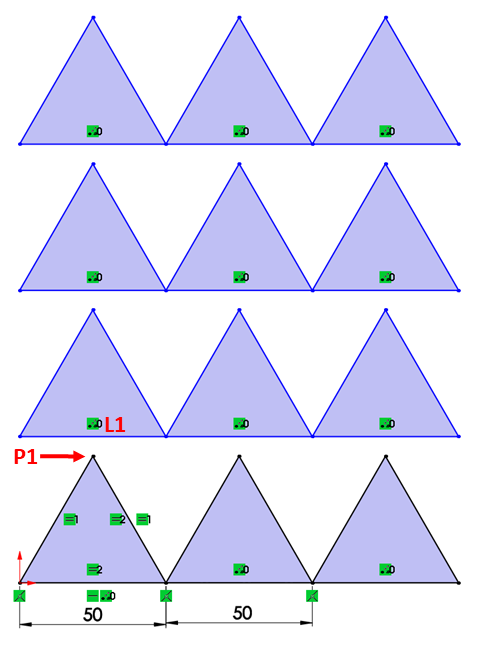
- To fully define the pattern, we can define the shapes in the Y direction. We will need to add a Midpoint relation between L1 and P1. This will make the sketch fully defined, as shown in the following diagram:

Let's have a look at some related commands:
- Instances to Skip: At the bottom of the Linear Pattern options, we will find the Instances to Skip option. We can use this to skip instances of the pattern. For example, in the preceding exercise, we can remove the two middle triangles by adding them to the Instances to Skip. This will exclude the middle triangles from the pattern:

- Edit Linear Patterns: To edit an existing linear pattern, we can right-click on any of the patterned instances and select the Edit Linear Pattern option, as shown in the following screenshot:

- Delete Linear Patterns: To delete the pattern (or parts of it), we can simply select or highlight those entities and press Delete on the keyboard.
This concludes this exercise on using linear patterns. In the exercise, we have covered the following topics:
- How to set up and define linear patterns
- The different options that we can use to define a linear pattern
- How the linear pattern entities interact as under defined entities
Now that we have mastered linear patterns, let's move on and look at circular patterns.