
Chapter 8: Outlining the OSI Model
Effective packet analysis begins with a solid understanding of the Open Systems Interconnection (OSI) model. The OSI model is a seven-layer framework that outlines how the operating system (OS) transforms, encapsulates, and prepares data for transport on the network. In this chapter, we'll cover the seven layers and the role and purpose of each layer. Additionally, you'll learn how within the OSI model, there are three layers that use a specific address or identifier. The Transport layer has an associated port, The Network layer uses an Internet Protocol (IP) address, and the Data Link layer requires a Media Access Control (MAC) address. So that you are able to differentiate identifiers for each of the layers, we'll review and describe the significance of each one.
Then, we'll take a look at the Protocol Data Unit (PDU) for each layer.
Once done, you will be more familiar with the terminology and have a better understanding of some of the protocols in each layer. From the Hypertext Transfer Protocol (HTTP) request when retrieving data from a web page to the bits as it travels across the network, you'll know how data transforms. In addition, we'll learn how each PDU feeds into the next layer to properly format the frame so that the data can be sent using the appropriate media.
In this chapter, we will cover the following main topics:
- An overview of the OSI model
- Discovering the purpose of each layer, the protocols, and the PDUs
- Exploring the encapsulation process
- Demonstrating frame formation in Wireshark
An overview of the OSI model
The OSI model is a seven-layer framework that outlines the main functions of each layer, which represents a grouping of protocols that perform a specific function. Understanding the model will better prepare you for analyzing traffic with Wireshark. In addition, you'll be able to recognize the role of the protocols involved during a transaction.
Note
All protocols have a specific purpose on the network. Today, Wireshark has dissectors for most protocols, and new ones are added all the time.
In this section, we'll take a step back and learn how the framework began, along with recognizing who benefits from using this model.
Let's start with the inspiration behind the OSI model.
Developing the framework
We started this journey during the period of the late 1960s to the mid-1970s, where we saw an expansion in computing, along with advances in technology in general. In addition to this, we witnessed the development of computers, from small personal computers to supercomputers, such as the Cray in 1976, and video games, such as Pong, in 1972.
Concurrent to this development, two international organizations, the International Organization for Standardization (ISO) and the International Telegraph and Telephone Consultative Committee (CCIT), began working on a reference model to define and standardize networking interoperability. Ultimately, in 1983, the two organizations developed the OSI model.
The OSI model serves many purposes, including the following:
- Providing a common framework for developers
- Narrowing down problems for network administrators
- Enabling interoperability among layers and devices communicating with one another.
- Breaking down each layer to help students better understand the overall process of data encapsulation.
As a result, many individuals benefit from using the OSI model, as we will outline next.
Using the framework
While the OSI model is a reference model, there are many groups that utilize it. These groups include the following:
- Developers reference the OSI model to outline how systems communicate with one another.
- Network administrators refer to issues according to the layer they feel is responsible for the malfunction when troubleshooting network problems.
- Equipment manufacturers rely on the OSI model to ensure their products will work across all layers.
Additionally, students use the model to begin their journey into networking. A staple of every college freshman networking class is an introduction to the OSI model. In most cases, these students have never heard of this, so presenting a complex topic in a simple manner can be difficult. As this is their first encounter, it's important to convey this information in an easy-to-learn manner.
In addition, the model provides a visual description of what is going on in each layer. The model defines the protocols, PDUs, and the purpose of each layer, as outlined in the following section.
Discovering the purpose of each layer, the protocols, and the PDUs
In this section, we'll take a closer look at each of the seven layers of the OSI model and describe the following:
- The layers of the OSI model, from layer seven to layer one: Application, Presentation, Session, Transport, Network, Data Link, and Physical.
- The three layers that use source addressing and destination addressing during encapsulation: the Transport, Network, and Data Link layers.
- The PDU for each layer, which defines what shape the data is in as it is passed to the layer above or the layer below.
In the following diagram, we can see a summary of the OSI model:

Figure 8.1 – The OSI model
Before diving into the layers, it is helpful to use a mnemonic device to remember the first letter of each layer. With the OSI, we have two, as shown in the following diagram:
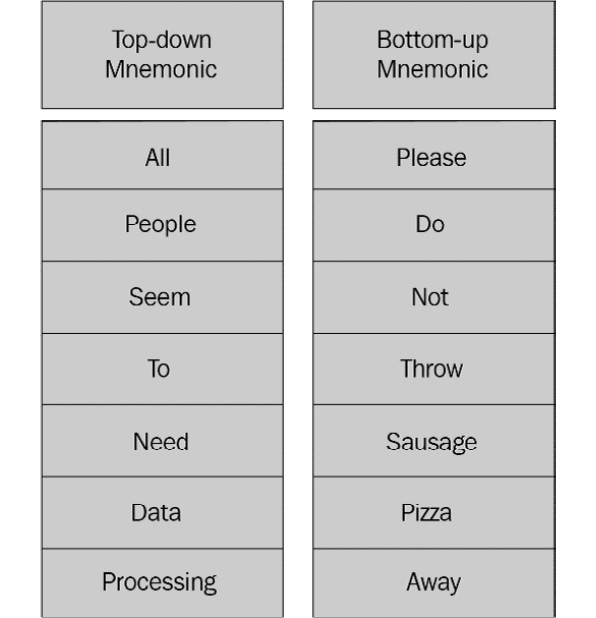
Figure 8.2 – OSI mnemonics
Once you know the names of the layers, the next step is to tackle the role, purpose, and protocols of each of the layers.
When outlining each layer, usually, I start with the Application layer, as this is where we initiate contact with the network. Let's discuss this next.
Evaluating the Application layer
The Application layer (or layer 7) contains the protocols that allow process-to-process communications, which enable us to do the following:
- Retrieve a web page
- Fetch or send email
- Upload files to an FTP server
- Request a dynamically assigned IP address
On a TCP/IP network, each Application layer protocol follows specific recommendations, requirements, and options, according to its function. Let's talk about a few of the protocols alongside the PDU for this layer.
Exploring the Application layer protocols
The Application layer has hundreds of protocols. Many common or well-known protocols were developed and standardized very early in the 1980s. Some are deprecated and we rarely see them, such as Telnet and Simple Authentication and Security Layer (SASL). However, new protocols are developed, as needed, to keep up with today's demands, such as Constrained Application Protocol (CoAP) and Message Queuing Telemetry Transport (MQTT), which are both used with Internet of Things (IoT) devices. The following is a shortlist of Application layer protocols:

Table 8. 1 – The Application layer protocols
In many cases, the protocols in this layer are involved in a series of client requests and server responses. Next, let's talk about the PDU for this layer.
Understanding the Application layer PDU
The PDU for the Application layer is data that is specific to the protocol in use.
The header structure for each protocol will vary, as each is application-specific. In addition to this, the header for the client is generally different from the header for the server.
Most protocols will have an associated port, which will be found in the Transport layer header. The following is a summary of the Application layer:

Table 8. 2 – Summary of the Application layer
After the data leaves the Application layer, it is then passed to the Presentation layer, in order to properly format the data. Let's explore this next.
Dissecting the Presentation layer
The Presentation layer (or layer 6) is responsible for proper data formatting, along with optional compression and encryption. This layer ensures that the data is in the proper format, either before presenting the data to the application (such as a Word document) or prior to sending it out onto the network. For example, if you download a file from the internet with the .gz extension, then the Presentation layer will search for an application to associate it with, so the OS can open the file correctly. If the application is not installed, then you will see a message, as shown in the following screenshot:

Figure 8.3 – The dialog box to select an application
If you do not have the application installed, then you can go in and manually select the application with which you want to open the file or obtain and install the correct application.
The Presentation layer also provides optional services in which to compress and decompress data. Compression removes redundancy and makes data smaller. This function is optional, as not all data is compressed.
Additionally, this layer handles encryption, which involves scrambling data using a key so that it is in an unreadable format that does not make sense to anyone unless they have the key. Because encryption is also an optional function, this might not be required.
In the Presentation layer, there are a few protocols, which we'll investigate in the following section, along with the PDU.
Describing the protocols and the PDU
In this layer, the protocols deal with proper data translation and encoding/decoding, such as External Data Representation (XDR). In addition, because of the Presentation layer's role in encryption, you'll find the following protocols:
- Transport Layer Security (TLS)/Secure Socket Layer (SSL): These protocols secure end-to-end communications such as bank transactions and web page retrieval using encryption.
- Secure/Multipart Internet Mail Extensions (S/MIME): These protocols digitally sign and encrypt email messages.
At the Presentation layer, the PDU is still data, and we see the data being translated or converted into the correct format. The following is a summary of the presentation layer:

Table 8.3 – Summary of the Presentation layer
In many ways, the Presentation layer is an extension of the Application layer. Next is the Session layer, where we see all of the key elements of session management.
Learning about the Session layer
The Session layer (or layer 5) is responsible for setting up, maintaining, and tearing down a session. Before any data is exchanged after initiating contact with the network, the OS must establish a session. When creating a session, the OS will create the appropriate socket, which is an IP address, and a port. This is so that the two endpoints can exchange data with one another.
When communicating on the network, you will have multiple concurrent sessions and connections established. You can see your active connections by going to the command line and running netstat, as shown in the following screenshot:
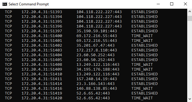
Figure 8.4 – Netstat showing active connections
In the preceding screenshot, we only see Transmission Control Protocol (TCP) connections. TCP is a connection-oriented protocol and both endpoints need to communicate the status of the data transaction with one another. As a result, you will see a local and foreign address, along with the state of the transaction. For example, the following represents a connection:
TCP 172.20.4.31:51393 104.118.222.227:443 ESTABLISHED
In addition to managing the communication between two endpoints, the Session layer provides other services that include the following:
- Authentication: This validates and identifies an entity by requiring a password or another form of authentication.
- Authorization: This allows access to system resources if the entity has the appropriate permissions.
- Checkpointing: This monitors the session for errors and ensures that all data has been received. If there are errors in transmission, the Session layer might re-request any missing data.
After the communication stream has ended, the Session layer safely closes the session. Next, let's look at some of the key protocols in this layer.
Recognizing the protocols and the PDU
There are several protocols that exist in the Session layer. Although most protocols might originate in other layers, these protocols begin, in part, in the Session layer:
- Real-Time Transport Control Protocol (RTCP): This works alongside the Real-Time Transport Protocol (RTP) to deliver control information to all participants in a Voice over IP (VoIP) call.
- Domain Name System (DNS): This resolves a hostname to an IP address in order for a session to take place.
- Point-to-Point Tunneling Protocol (PPTP): This creates a VPN by using a generic routing encapsulation tunnel to provide a more secure way to deliver data than using plain text.
- Remote Procedure Call (RPC): This allows a program to run a subroutine on another host on a shared network.
At the Session layer, the PDU is data. The following is a summary of the Session layer:

Table 8.4 – Summary of the Session layer
The Session layer manages all aspects of a session, enabling hosts to communicate in a conversation with one another. At this point, the data then moves to the Transport layer, where it now becomes a segment that has the necessary port addressing in the Transport layer header.
Appreciating the Transport layer
The Transport layer (or layer 4) is responsible for transporting the data, either using a connectionless or connection-oriented protocol across the network. The encapsulation process starts at this layer. The data will have additional headers added as it traverses down the layers to become a frame, ready to be sent on the network.
The transport protocol that is selected will depend on the application. Data is primarily transported using either TCP or User Datagram Protocol (UDP). However, the Transport layer has several other protocols. Let's take a look at them.
Differentiating the protocols and the PDU
The Transport layer has several protocols to transport data, including the following:

Table 8.5 – Common protocols in the Transport layer
Although there are other lesser-known Transport layer protocols, we will discuss the two predominant protocols, TCP and UDP, starting with the more widely used protocol, TCP.
Providing reliability with TCP
TCP is a connection-oriented protocol that has end-to-end reliability. TCP begins a session with a three-way handshake and ends the session with an exchange of finis (FIN) packets.
TCP actively sequences and acknowledges data, using the field values in the 11-field header, to ensure that all the data arrives at the end device.
Once inside a connection, TCP progresses through a series of states. For example, in Figure 8.4, you can see the ESTABLISHED and TIME_WAIT states.
The TCP states are listed as follows:
- LISTEN: The system waits for a request from a remote host to connect.
- SYN_SENT: After the client sends a request for a connection, the system waits for a response.
- SYN_RECEIVED: After the SYN request has been returned to the client, the server waits for a final ACK to start the connection.
- ESTABLISHED: This is a normal state where the two endpoints are actively communicating.
- FIN_WAIT_1: The host waits for either an ACK in response to a FIN sent to the remote host or a FIN request from the remote host.
- FIN_WAIT_2: The host waits for a FIN request from the remote host.
- CLOSE_WAIT: This means the server has received a FIN packet from the client and is waiting to end the session.
- CLOSING: After the FIN packet has been sent, the host begins closing the connection and waits for a corresponding acknowledgment, in order to fully close the session.
- LAST_ACK: A final acknowledgment after sending the FIN packet is made to ensure the remote host has received the termination request.
- TIME_WAIT: After sending a termination request, this state waits to ensure that the remote host has received the request to end the conversation.
- CLOSED: This is not a state at all; it represents a closed connection.
For a connection-oriented session where it is important to get all the parts of the communication stream, TCP is the Transport layer protocol of choice. However, when speed in data transport is required, UDP is the better choice. UDP is a connectionless protocol with only four field values, as we will learn next.
Ensuring a timely delivery with UDP
UDP is a connectionless and lightweight Transport layer protocol that has a four-field header. UDP doesn't have any handshake or connection process, ordering or reliability services, and there's no teardown. As a lightweight protocol, it's ideal where speed is an issue and is used with time-sensitive applications, such as the following:
- Dynamic Host Configuration Protocol (DHCP)
- Routing Information Protocol (RIP)
- Voice over Internet Protocol (VoIP)
- Trivial File Transfer Protocol (TFTP).
Whether TCP or UDP is in use, the Transport layer is a critical component to ensure data transport. During the encapsulation process, the data begins to transform, and the PDU is now a segment. At this point, the Transport layer requires a port number (or address) that is associated with an application or process that is in use. This is discussed in the following section.
Providing port addressing
At the Transport layer, we add a port address, which is used to identify a specific application or process. Port numbers fall into three main groups:
- Well-known ports range between 1 and 1,023 and include protocols such as HTTP, DNS, and SMTP.
- Registered ports range between 1,024 and 49,151 and are assigned and used for specific services such as gaming applications, OpenVPN, and IPsec.
- Dynamic, private, or ephemeral ports are in the range of 49,152–65,535 and are not assigned to any specific application. They are used temporarily during a session, generally by the client.
When the Transport layer header is applied to the data, a source and destination port are added. The type of port used depends on whether the packet is coming from the client or the server:
- If a client sends a packet, then the source port will be (in most cases) a randomly assigned dynamic or ephemeral port that is used. So, when the server delivers a packet to the host, it uses that port to deliver the data.
- If a server sends a packet, then the source port will be either a well-known port or a registered port.
The Transport layer provides inter-host communication between endpoints. The following outlines a summary of the Transport layer:

Table 8.6 – Summary of the Transport layer
After the Transport layer, the next layer is the Network layer. As we'll see in the next section, this layer is all about getting the data to the correct network.
Explaining the Network layer
The Network layer (or layer 3) has two key roles: addressing and routing data. This layer provides addressing using a logical IP address. In addition, the Network layer determines the best logical path to take for packets that travel through other networks, so they can get to their destination. It does this by communicating with other devices during the routing process.
In addition to data forwarding, the Network layer communicates errors in transmission. In order to achieve this, the Network layer has a few key protocols, as we will see in the following section.
Distinguishing the protocols and the PDU
The Network layer is responsible for addressing and routing. There are three main protocols in this layer: IP, Address Resolution Protocol (ARP), and Internet Control Message Protocol (ICMP). Let's start with IP.
Routing packets with the IP
IP is a best-effort, connectionless protocol that routes packets from the source to the destination using a logical IP address.
Over the years, many of the original protocols in the TCP/IP suite have had minor changes, updates, and modifications. However, IP had to make a major change, which was mainly due to a lack of address space. As a result, there are two versions of IP: IPv4 and IPv6. The following outlines a brief comparison of the two:
- IPv4 has a 32-bit address space. The use of private IP addresses has extended IPv4's lifespan on a LAN, but there is a slow migration to IPv6.
- IPv6 has a 128-bit address space and offers enhancements to the protocol in general, such as simplified network configuration and more efficient routing.
Next, we will look at ARP, which resolves an IP address to a MAC address.
Resolving addresses with ARP
IP routes traffic through networks to its destination LAN. When a packet arrives on the LAN, it no longer needs an IP address. It requires a physical or MAC address to go to its destination. ARP issues a broadcast to resolve an IPv4 address to a MAC address on a local area network (LAN) so that the frame can be delivered.
Note
ARP is an unusual protocol because it appears between layer three and layer two of the OSI model. ARP resolves an IP address (the Network layer) to a MAC address (the Data Link layer) address. However, many consider it to be a layer three protocol.
In addition to IP and ARP, we also need ICMP to help report any problems that might have occurred during data transport. This is discussed in the following segment.
Conveying messages with ICMP
ICMP is another critical network protocol. However, ICMP does not exchange or transport data. Its primary role is error reporting. Because IP is a best-effort, unreliable protocol, ICMP must be implemented by every IP module, as outlined in the original Request for Comment (RFC), which can be found at https://tools.ietf.org/html/rfc792. ICMP reports on any issues encountered during transit such as the network being unreachable and the host being unreachable. Because there are two IP versions, there are two versions of ICMP:
- IPv4 uses ICMP.
- IPv6 uses ICMPv6.
During the encapsulation process, the PDU at the Network layer is a packet. The Network layer is responsible for routing and addressing data. One key element is an IP (or logical) address, as described next.
Supplying an IP address for the packet
In this layer, the IP header will hold the source and destination addresses in either IPv4 format or IPv6 format. Both are referred to as logical addresses and are represented as follows:
- An IPv4 address has 32 bits, which Wireshark will display using dotted decimal notation.
- An IPv6 address has 128 bits, which Wireshark will display using hexadecimal numbers, separated by colons.
In the previous section, we discussed two other protocols: ARP and ICMP. Let's discuss both of these in relation to the need for addressing.
We know that IP uses a header that houses an IP address. However, ARP and ICMP are both unique, as outlined here:
- ARP does not have an IP header. ARP is a service protocol that resolves an IPv4 address to a MAC address.
- ICMP is the partner protocol to IP, and it reports on matters encountered during transit, such as the network being unreachable and the host being unreachable. ICMP itself does not need an IP address, as it is encapsulated in an IP header, as shown in the following screenshot of an ICMP echo request:

Figure 8.5 – An ICMP echo request
By now, you should have understood that the Network layer allows hosts on separate networks to communicate with one another by providing logical addressing and path determination.
The following table outlines a summary of the Network layer:

Table 8.7 – Summary of the Network layer
As data is encapsulated and passed down the OSI model, the next step is the Data Link layer, where a key role is proper frame formation so that the frame can travel on the LAN. Let's take a look.
Examining the Data Link layer
The Data Link layer (or layer 2) is primarily concerned with proper frame formation and prepares the data before it is sent out on the network. Within the Data Link layer, there are several protocols that are responsible for properly formatting the data so that it can successfully traverse on the destination network. Let's focus on a few key Data Link layer protocols next.
Investigating protocols and the PDU
The Data Link layer is the final stop as data travels down the OSI model, as this layer adds a frame header and trailer to ready the frame for the network. Protocols used in this layer include the following:
- Ethernet II is the most widely used Ethernet technology today. It establishes connections on a LAN using the physical (or MAC) address.
- High-Level Data Link Control (HDLC) uses frames to deliver data from point to point.
At this layer, the PDU is a frame. Each frame requires an address, which we will outline next.
Describing the Data Link layer address
On a LAN, the Data Link layer uses the MAC address of the destination machine rather than the IP address. The Data Link layer has a frame header that contains the source and destination MAC address, which is also referred to as a physical address. The trailer, or frame check sequence, holds a value called a Cyclic Redundancy Check (CRC), which is used for error detection on a network.
The following table provides a summary of the Data Link layer:

Table 8.8 – Summary of the Data Link layer
The Data Link layer ensures proper frame formation and link access, along with error detection, while traveling across the network media. Data then travels to the Physical layer, as we will see in the following section.
Traveling over the Physical layer
The Physical layer (or layer 1) transmits data over media in a stream of bits.
Once data is formatted into a frame, the Network Interface Card (NIC) sends it on to the network media in a stream of bits.
Exemplifying protocols
In the Physical layer, there are several different protocols used to transmit data across the network media:
- Digital Subscriber Line (DSL) provides broadband to residences and businesses using a phone line.
- Integrated Services Digital Network (ISDN) transmits voice, video, and data using the Public Switched Telephone Network (PSTN). ISDN is primarily used in the broadcasting industry.
- IEEE 802.3—the Ethernet Physical layer—defines the transmission properties according to the media type, such as fast Ethernet and Gigabit (GB) Ethernet.
The Physical layer is where binary transmission takes place across the network media. Let's review the PDU for this layer.
Describing the PDU
At this layer, the frame formation is complete and ready to travel over the media. The PDU is in the most basic form, which is bits. The method of transmission will depend on the medium.
Network media includes the following:
- Copper cable using Unshielded Twisted Pairs (UTP), Shielded Twisted Pairs (STP), or coaxial; transmits with pulses of electricity
- Fiber using a multimode or single-mode cable; transmits with pulses of light
- Wireless using 802.11 specifications; transmits over radio waves
The following table provides a summary of the Physical layer:

Table 8.9 – Summary of the Physical layer
Prior to traveling through the network, the data must be in the correct format. The next section explores the encapsulation process, which adds headers and addresses and readies the data for transport through the media.
Exploring the encapsulation process
Now that we have gained an understanding of the layers, let's look at how each of the layers works together during the encapsulation process to create a frame.
During frame formation, the process begins with data. As the data moves down the layers, a header is added, one by one, until the frame is complete. Each frame has the following components:
- Data and an appropriate Application layer header (if applicable)
- A segment header
- A packet (or IP) header
- A frame header
We'll start with the data portion of the frame.
Viewing the data
In most cases, when frame formation begins and encapsulation takes place, we start with the data, as shown here:

Figure 8.6 – The encapsulation process—data
The data might be any of the following:
- An HTTP GET request
- A DNS request to resolve a hostname to an IP address
- A DHCP broadcast to request a dynamically assigned IP address
The data then continues its journey to becoming a segment.
Identifying the segment
The next thing that happens is that the data will (in most cases) become a segment that will use either a TCP header or a UDP header:

Figure 8.7 – The encapsulation process—segment
The segment holds a source and destination port address, as shown in Figure 8.7. The next stop in the encapsulation process is to add an IP header in order for it to become a packet. We will discuss this next.
Characterizing the packet
As data is encapsulated, we now have data, along with a segment that holds either a TCP or UDP port address. The next part of encapsulation is to create a packet by adding the source and destination IPv4 or IPv6 address to the IP header, as shown here:

Figure 8.8 – The encapsulation process—packet
The final part of the encapsulation process is the addition of the frame header, which is demonstrated in the next section.
Forming the frame
The last stop on the journey of creating a frame is the addition of the header. Within the frame, we have the following:
- The data, such as an HTTP request or DNS reply
- A Transport layer header (or segment)
- A Network layer header (or packet)
At this point, we complete the frame by adding the source and destination MAC addresses, as shown here:

Figure 8.9 – The encapsulation process—frame
With a frame, not only do we have a header, but we also have a trailer, which is called the Frame Check Sequence (FCS). The FCS holds a value called a cyclic redundancy check, which is used for error detection on the network and is checked while traveling along on its journey.
Note
The FCS is used for error detection, not error correction.
The next section covers how the frame formation looks when Wireshark captures the traffic and presents it to the user.
Demonstrating frame formation in Wireshark
Once you understand encapsulation and frame formation, you will be able to learn how Wireshark represents frame formation, as shown in the following screenshot:

Figure 8.10 – Frame formation in Wireshark
Note
Not all frames contain data; however, this one does, so it's a good example of a fully encapsulated frame.
When looking at a single frame, you will see at the top of Figure 8.10, the Frame 4371 line, which is the metadata about that single frame that summarizes the contents of the frame. The metadata for this frame includes information such as 401 bytes on wire and 401 bytes captured.
After the frame metadata, you will have the following:
- Frame: The frame header shows Ethernet II, and after that are the source and destination MAC addresses.
- Packet: The IP header represents the Network layer, which holds the source and destination IP addresses.
- Segment: The TCP header represents the Transport layer, which holds the source and destination port addresses.
- Data: The HTTP header represents the Application layer. In this case, it is a web request.
This is an example of how Wireshark displays the encapsulation process and how it relates to the OSI model.
Now that you have learned about the encapsulation process and frame formation in Wireshark, let's take a look at the NIC and see the OSI model in action on your own system.
Examining the network bindings
On your own laptop or desktop, you can easily see the OSI model in action. If you check your network connections and then select the properties of your network interface card, as shown in the following screenshot, you can see how the layers in the OSI model are represented:
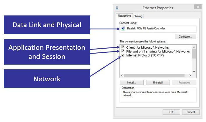
Figure 8.11 – Network bindings
The following represents the various layers and how they are represented in Ethernet Properties:
- The Data Link and Physical layers are represented in the NIC.
- The Application, Presentation, and Session layers are represented in Client for Microsoft Networks and File and print sharing for Microsoft Networks.
- The Network layers are shown as Internet Protocol (TCP/IP).
By now, you should be able to recognize each of the layers of the OSI model, along with how each layer is represented in Wireshark.
Summary
In this chapter, we took a closer look at an important concept, the OSI model and the encapsulation process. The OSI model is a framework that serves many purposes. The model provides a common framework for developers and a method to help students understand what process occurs at each layer. In addition to this, understanding each of the layers, the PDU, and the addressing will help you to better comprehend the process in Wireshark and improve your data analysis skills.
By now, you should have a better understanding of the role, purpose, protocols, and PDU of each layer. We explored the encapsulation process and took a look at frame formation as it is seen in Wireshark. To help you understand how your system uses the OSI model, we looked at how the model is represented in the network bindings.
In the next chapter, we'll take a closer look at how to decode the two main Transport layers: TCP and UDP. We'll begin by reviewing the purpose of the Transport layer and then discuss TCP and examine the 11-field header format in Wireshark. Then, we'll go through an overview of the purpose of UDP and examine the four-field header and the significance of each field value.
Questions
Now it's time to check your knowledge. Select the best responses, and then check your answers with those listed in the Assessment appendix:
- The _____ layer, or layer 5, is responsible for setting up, maintaining, and tearing down a session.
- Transport
- Application
- Session
- Presentation
- The _____ layer, or layer 4, is responsible for transporting the data, either using a connectionless protocol or a connection-oriented protocol.
- Transport
- Application
- Session
- Presentation
- The _____ layer, or layer 6, is responsible for proper data formatting along with optional compression and encryption.
- Transport
- Application
- Session
- Presentation
- TCP port 334 is in the range of the _____ ports.
- Ephemeral
- Well-known
- Registered
- Secure
- The PDU at the transport layer is _____.
- Data
- Frame
- Packet
- Segment
- ARP does not have a(n) _____ header because it is a service protocol that resolves IPv4 addresses to MAC addresses.
- Data Link
- Frame
- IP
- Segment
- On a LAN, the Data Link layer uses the _____ address of the destination machine rather than the IP address.
- MAC
- Ephemeral
- Packet
- Segment