
Chapter 13. HLSL Basics
Let’s take a break from developing the game for a minute and talk about High Level Shader Language (HLSL). Pre-XNA, DirectX allowed developers to send instructions directly to the graphics device through a mechanism called the Fixed Function Pipeline (FFP). This worked fine for a while, until graphics cards and hardware began to become incredibly complex. The more capabilities that were added to the hardware, the more detailed and complex the FFP needed to become to allow developers to take full advantage of that hardware.
Tip
Even on modern cards, the FFP is implemented as a shader—just one
that operates behind the scenes. This is very similar to the way that
BasicEffect gives developers access
to a simple version of the FFP.
Instead of continually adding features to the FFP and extending it, Microsoft decided instead to allow developers to talk directly to the hardware devices in a different language built specifically for those devices.
The first attempt to solve this problem was to allow developers to program directly to the hardware using assembly language. While this approach was functional, developers still needed a higher-level language to develop in. Enter HLSL. HLSL began as a joint project between Microsoft and NVIDIA. At some point, however, the development effort split, and NVIDIA’s language (called C for Graphics, or Cg) went one route and Microsoft’s language (called HLSL) went another.
HLSL allows developers to write in a language that is similar to C and that translates into assembly language on the graphics card itself. By using HLSL, developers can access all the functions of the graphics card without having to use an API such as the FFP.
As mentioned in previous chapters of this book, everything drawn in
XNA 3D uses HLSL. The XNA development team at
Microsoft was kind enough to add the BasicEffect class, which you’ve used in examples up until now, to enable
developers to learn XNA without having to first study up on HLSL. However,
even the BasicEffect class simply
passes the data to an internal HLSL process.
Tip
One thing that played into the decision to add the BasicEffect class to the XNA Framework was the
fact that the FFP is not supported on the Xbox 360’s Graphics Processing
Unit (GPU). This meant that the developers at Microsoft were faced
with a dilemma: should they support the FFP on the PC and force code
rewrites for all Xbox 360 games, or invent a massive shader that
implements the FFP? Ultimately, they decided to take an in-between approach
that gives developers enough to get
up and running without having to deal with shader code (the
BasicEffect
class).
In HLSL, developers write shaders that can access the most complex graphics hardware features. Graphics cards can support two different types of shaders: vertex shaders and pixel shaders. Vertex shaders are run once for every vertex in the viewing frustum, or field of view. Pixel shaders are run on every visible pixel in all visible objects drawn in the scene.
To understand a little more about the shader process in HLSL, look at Figure 13-1.
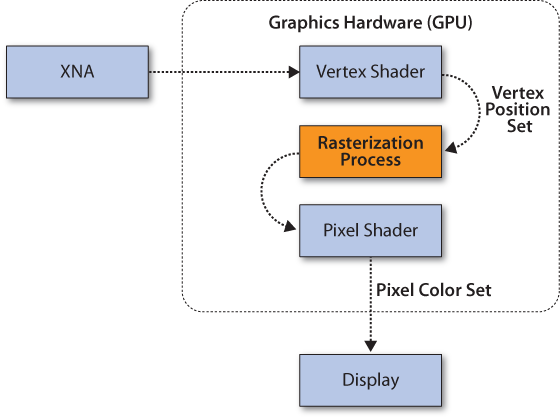
The shader process first runs any vertex shaders, once for every vertex in the scene. The goal of a vertex shader is to set the positions of the vertices based on the world and camera settings. Once the position data is received from the vertex shader, a rasterization process takes place. Rasterization is the process that transforms a triangle into a set of pixels to be rendered on the screen.
After the scene has been rasterized, the pixel shader runs on each pixel that is drawn in the scene. The goal of a pixel shader is to define the color of each visible pixel.
Tip
Before the pixel shader runs, a depth check is run on each pixel. This enables identification of pixels that are within the field of view but are hidden because another object is in front of them, so that the pixel shader is not unnecessarily run on them.
After the pixel shader runs, the data is output to the screen.
HLSL Syntax
HLSL is a language that resembles C. I will warn you before we get into this section that programming shaders in HLSL is very different than programming in XNA. If you don’t get it and feel lost, don’t get too stressed about it. In fact, in many game development shops it is not uncommon for there to be a team of game developers who write shaders and a separate team of game developers who write in DirectX or XNA—mainly because they really are two different skill sets.
That said, HLSL is an integral part of XNA development, and this book would be incomplete if it didn’t cover it to some extent. In this chapter, we’ll look at HLSL basics and go over some sample code, but this book is not meant to be an end-all, be-all HLSL resource. There are entire books devoted to that subject; if you’re looking to get really deep into HLSL, you can pick up the basics here and then deepen your knowledge using those resources.
OK, that’s my disclaimer. Let’s get to the action.
Variables in HLSL are declared much the same way as in C#. In fact,
many of the variables use the same keywords as in C# (e.g., HLSL has
keywords such as int, float, bool, string, true, false, return, void, etc.).
More complex objects are typically represented as structs, which are also defined the same way
that they are in C#. One very common way of representing data in 3D
graphics is to use a vector. Vectors can be defined using a
vector keyword, but they’re more
commonly defined as float3s for
vectors with three elements and float4s for vectors with four elements.
float3 and float4 variables are essentially arrays of floating-point values. Vectors
defined this way most commonly represent either colors or positions. As
an example, you can define a new float4 variable and initialize its value using
the following line:
float4 color = float4(1, 0, 0, 1);
This defines a float4 variable
called color. You can access
individual elements in the float4
variable by using array notation, as shown here:
float red = color[0];
In addition to array notation, you can use special namespace
accessors for the float4
datatype. As mentioned earlier, a float4 can represent a color or a position. As
such, the four elements in the array can correspond to either r, g,
b, and a or x,
y, z, and w.
To access a variable’s elements using these namespaces, you can use code
similar to the following:
float blue = color.b;
float z  = color.z;
Notice that you can use either rgba or xyzw to access the same variable. In fact, you
can actually combine the elements of the array into a new array and
access the elements in any order. The following code reverses the array
by accessing the elements in reverse order:
float4 reverse = color.abgr;
Accessing multiple elements at one time, as shown in the previous line of code, is called swizzling. You can swizzle the elements in any order, but you cannot swizzle across color and position namespaces. For example, this code would result in a compilation error:
// This won't compile
float4 reverse = color.axgy;
Another important variable type worth noting is the matrix that is
created using the
floatRxC
keyword (where R equals the number of rows
and C equals the number of columns). You can
also use the matrix keyword to create
matrix variables. Both of the following lines will create a 4×4
matrix:
float4x4 matrixFun;
matrix <float, 4, 4> matrixMadness;
Finally, as mentioned earlier, structs are created in HLSL the same way that
they are created in C#, so you can use the following code to create a
struct in HLSL:
struct myStruct
{
    float4 position;

};
Dissecting a Sample HLSL Effect File
In XNA, effects are created in effect files, which have an .fx extension. They are loaded via the content pipeline and are compiled just like other content resources. Therefore, the compiler will detect compilation errors in your HLSL code just like it will in your C# code, even though your effect files are stored with other content.
Tip
Although your HLSL code will be compiled via the content pipeline, unfortunately you won’t have access to IntelliSense when working with HLSL effect files.
Now that you have the basics of the HLSL language down, let’s take a look at a sample effect file created using HLSL. In this section, we’ll dissect the different sections of this example file:
float4x4 World;
float4x4 View;
float4x4 Projection;

struct VertexShaderInput
{
    float4 Position : POSITION0;
};

struct VertexShaderOutput
{
    float4 Position : POSITION0;
};

VertexShaderOutput VertexShaderFunction(VertexShaderInput input)
{
    VertexShaderOutput output;

    float4 worldPosition = mul(input.Position, World);
    float4 viewPosition = mul(worldPosition, View);
    output.Position = mul(viewPosition, Projection);

    return output;
}

float4 PixelShaderFunction(VertexShaderOutput input) : COLOR0
{
    return float4(1, 0, 0, 1);
}

technique Technique1
{    pass Pass1
    {
        VertexShader = compile vs_2_0 VertexShaderFunction();
        PixelShader = compile ps_2_0 PixelShaderFunction();
    }
}
Don’t be too scared by this code. It looks a bit different than what you’re used to in XNA, but we’ll explore each section of the code here so you can figure out what it’s doing.
First, let’s look at the top three lines of the file:
float4x4 World;
float4x4 View;
float4x4 Projection;
These three lines represent global variables in this file. All three variables are 4×4 matrices; they correspond to the world, the camera view, and the camera projection. These terms should be pretty familiar to you by now because they are the same world, view, and projection that you’ve used in previous examples in this book when drawing in 3D.
Variables that are in this global space can be set from your XNA code. (You’ll see more about how to do that later, when you apply this code to an actual project.) When using an HLSL file in XNA, one of the first things to do is look for what variables need to be set from the XNA code.
Just like when you’re programming in C or C++, in HLSL, variables
and functions need to be defined before they are used.
This means that a typical flow for an HLSL file will have variables at
the top, followed by structs,
functions, and finally the shader calls themselves.
When reading an HLSL file, it typically makes sense to read it in
the order in which it will be executed. So, let’s next skip to the
bottom of the code in the sample file. Here’s the section of the file
that uses the technique
keyword:
technique Technique1
{
    pass Pass1
    {
        VertexShader = compile vs_2_0 VertexShaderFunction();
        PixelShader = compile ps_2_0 PixelShaderFunction();
    }
}
Each HLSL effect file will have one or more techniques. In your
XNA code, you’ll specify which technique to run when applying an HLSL
file by referring to the name of the technique, which in this case is
Technique1.
Inside the technique section,
notice that there is a subsection called a pass. Each technique has one or more passes.
When you draw in XNA using a custom HLSL effect file, you’ll set the
technique as mentioned earlier and then loop through all the passes to
draw each of them. This particular technique has only one pass (Pass1).
Each pass can contain a vertex and/or pixel shader. To implement a
shader, your HLSL file must set the value of the VertexShader and/or PixelShader object(s) equal to a compiled
vertex or pixel shader function.
Let’s look at those two lines in more depth:
VertexShader = compile vs_2_0 VertexShaderFunction();
PixelShader = compile ps_2_0 PixelShaderFunction();
The VertexShader and PixelShader
objects are HLSL objects whose names must be spelled exactly that
way and are case-sensitive. The keyword compile tells XNA to compile the method that
follows using a certain version of vertex shader or pixel shader (in
this case, you’re compiling using vertex shader version 2.0, as
specified by vs_2_0, and pixel shader version 2.0, as specified by
ps_2_0). The functions (VertexShaderFunction( ) and PixelShaderFunction( )) were defined earlier
in the file. The first of those to be called is the vertex shader, so
next we’ll look at the vertex shader function.
The vertex shader function is listed in the file as:
VertexShaderOutput VertexShaderFunction(VertexShaderInput input)
{
    VertexShaderOutput output;

    float4 worldPosition = mul(input.Position, World);
    float4 viewPosition = mul(worldPosition, View);
    output.Position = mul(viewPosition, Projection);

    return output;
}
The first thing you’ll probably notice is that as an input type,
the function accepts a struct of type
VertexShaderInput (which was defined
earlier in the file). The return type is also a struct and is of type VertexShaderOutput (which was also defined
earlier in the file). Let’s take another look at these two structs:
struct VertexShaderInput
{
    float4 Position : POSITION0;

};

struct VertexShaderOutput
{
    float4 Position : POSITION0;

};
There’s really nothing unusual about these structs, other than one thing that you might
not have seen before: an HLSL semantic. The
POSITION0 code that appears after
each of the variable definitions is an HLSL semantic.
HLSL code uses semantics to link data from the XNA game that is using the HLSL code. When a semantic is specified on a variable, HLSL will automatically assign a value to that variable based on the semantic given. This is essentially a way to connect variables in HLSL with certain data to which the XNA game has access.
In this case, the vertex shader method accepts a parameter of type
VertexShaderInput, which contains a variable with a semantic of POSITION0. Specifying the POSITION0 semantic on the Position
variable causes HLSL to automatically set that variable to a position
value that is provided by the XNA game.
What position value will be automatically assigned? Remember that
a vertex shader runs once for every visible vertex, so the position
given via the POSITION0 semantic in a
vertex shader is the position of the vertex.
There are several other possible vertex shader input
semantics, in addition to POSITION0. These are listed in Table 13-1.
Semantic | Description | Type |
Binormal | | |
Blend indices | | |
Blend weights | | |
Diffuse and specular color | | |
Normal vector | | |
Vertex position in object space | | |
Transformed vertex position | | |
Point size | | |
Tangent | | |
Texture coordinates | |
You probably noticed that the vertex shader returns a struct as well, and that that struct also has a semantic of POSITION0 associated with it. Although the
semantic is the same, the meaning is different in this case because it
is used as a vertex shader output rather than an input. The meaning of
different semantics varies depending on whether the variable using a
particular semantic is being used for a pixel shader or a vertex shader
and whether it is being specified as input or output in that
shader.
For example, the semantics that can be applied to vertex shader output are different than those that can be applied to vertex shader input. Vertex shader output semantics are listed in Table 13-2.
Semantic | Description | Type |
Diffuse or specular color. | | |
Vertex fog. | | |
Position of a vertex in homogenous space. Compute position in screen-space by dividing (x, y, z) by w. Every vertex shader must write out a parameter with this semantic. | | |
Point size. | | |
Tessellation factor. | | |
Texture coordinate. | |
So, when the POSITION0 semantic
is applied to an input parameter in the vertex shader, HLSL
automatically assigns the vertex position to that parameter, but in
contrast, a semantic specified on an output parameter is used to flag a
variable as containing specific data.
Earlier, you read that the minimum job of any vertex shader is to
set the positions of all vertices in the scene, which is done by
specifying an output parameter with the POSITION[n] semantic. Essentially, your vertex
output needs to set the position of each vertex. But how do you do this,
given that there’s no vertex.position
variable or anything like that to set? That’s where the output semantic
comes in. By returning a value in a variable that has a semantic of
POSITION0, you’re specifying a return
value that denotes a position.
Freaking out about this? Don’t worry. Let’s take a look at the
actual vertex shader function. For your convenience, the function and
the structs it uses are shown again
here:
struct VertexShaderInput
{
    float4 Position : POSITION0;
};

struct VertexShaderOutput
{
    float4 Position : POSITION0;
};

VertexShaderOutput VertexShaderFunction(VertexShaderInput input)
{
    VertexShaderOutput output;

    float4 worldPosition = mul(input.Position, World);
    float4 viewPosition = mul(worldPosition, View);
    output.Position = mul(viewPosition, Projection);

    return output;
}
The first thing this code does is create a variable of type
VertexShaderOutput so that it can
return that datatype at the end of the function. Notice that that
struct has a variable called Position that has a semantic of POSITION0. Again, the basic responsibility of
a vertex shader is to set the position of each vertex. You can set the
position by returning a value tied to a
semantic of POSITION0. So, by
returning an object of type VertexShaderOutput, you’ll be setting the
position of the vertex, assuming that you set the Position member of that
VertexShaderOutput struct.
Next, the vertex shader function creates a variable called
worldPosition and sets the value of
that variable to the result of the mul function. What is the mul function? This is what’s called an
intrinsic function in HLSL: it’s a function that
HLSL provides for developers to manipulate data. A full list of
intrinsic functions is provided later in this chapter. This particular
function (mul) multiplies two
matrices together.
First, the vertex shader function multiplies the position of the
vertex (input.Position) by the
World matrix. How do you know that
input.Position represents the
position of the vertex? Well, once again, this comes back to semantics.
The input variable is of type VertexShaderInput, which is a struct defined prior to the definition of the
vertex shader function. The VertexShaderInput
struct has one member: Position. The Position member of that struct has a semantic of POSITION0. When the POSITION0 semantic is tied to a variable used
for vertex shader input, the position of the vertex is automatically
assigned to that variable.
Next, the vertex shader function multiplies the resulting matrix by the camera view. It then multiplies that resulting matrix by the camera projection and assigns that value to the output parameter, which it returns. All of that matrix multiplication sets the position of the vertex to the correct place, given the position and direction of the camera.
Tip
I know what you’re thinking: “Whoa…hold on a second. You’re telling me that if you multiply the position of a vertex by the object’s world matrix, then multiply that by the camera’s view matrix, and then multiply that by the camera’s projection matrix, it will magically set the position of the vertex to the correct place?”
Well, yes. And “magic” is really a good term for it. You don’t really need to understand how all of this works, and such a discussion would go way deeper into matrix multiplication than we want to in this book. But yes, multiplying those matrices together in that order will yield the correct position for the vertex. That just goes to show how fascinating and how powerful matrix multiplication can be.
You might also be wondering how the code sets the position of each vertex in the scene when only one position variable is returned from the function. Remember that the vertex shader will be run for every vertex in the scene. For example, if you drew a triangle and then ran this HLSL file to render that triangle, your vertex shader would run once for each vertex (there are three vertices in a triangle, so the vertex shader would run three times).
The parameter passed into the vertex shader has a semantic of
POSITION0, which will cause that
variable to be filled automatically with the value representing the
position of the vertex. So, if the vertices of the triangle you draw are
(0, 1, 0), (1, 0, 0), and (−1, 0,
0), your vertex shader will run three times: the first time the
input parameter value will be (0, 1, 0), the second time the input
parameter value will be (1, 0, 0), and the third time the value will be
(−1, 0, 0).
This might seem like a lot of confusing code, semantics, shaders, and so forth. Your head may be spinning. But that’s OK. Here are the key points to remember so far:
Global variables that aren’t given semantics or initial values need to be set from XNA code.
The name of the technique to run in your HLSL file needs to be set from XNA code.
An input parameter with a semantic will automatically receive the data represented by that semantic when the HLSL effect is executed (for example, an input parameter in a vertex shader with a semantic of
POSITION0will automatically be set to a value representing the position of the vertex).
An output variable with a semantic flags that variable as having a specific type of data for processing in the effect. This is how you “set” data in HLSL. If you need to “set” the position of a vertex in a vertex shader, you return a variable with a semantic of
POSITION0.A vertex shader has different semantics for input and output.
At a minimum, a vertex shader needs to specify a
POSITION[n]semantic for output.
Once the vertex shader finishes, the pixel shader will run. Let’s look at the pixel shader that was created in the effect file:
float4 PixelShaderFunction(VertexShaderOutput input) : COLOR0
{
    return float4(1, 0, 0, 1);
}
First, notice that the input parameter is the
VertexShaderOutput, the same type that was the output
from the VertexShaderFunction. This does not always
have to be the case. In fact, because vertex shader output semantics are
different than pixel shader input semantics, often they cannot be the
same type. And sometimes (as in this case), you don’t need to specify
any input to your pixel shader function at all. Table 13-3 shows a list of
valid pixel shader input semantics.
Semantic | Description | Type |
Diffuse or specular color | | |
Texture coordinates | | |
Floating-point scalar that indicates a back-facing primitive; a negative value faces backward, whereas a positive value faces the camera | | |
Contains the current pixel (x, y) location | |
Finally, notice the strange semantic on the function itself:
float4 PixelShaderFunction(VertexShaderOutput input) : COLOR0
This is another way of specifying a semantic for a return type.
You can also specify an input semantic in the parameter list rather than
using a struct. For example, the
following method returns a color and accepts one as well:
float myShader(float COLOR0) : COLOR0
Valid output semantics for pixel shaders are shown in Table 13-4.
As mentioned earlier, the minimum job of a pixel shader is to set
the color for each individual pixel. In this case, the pixel shader
function is returning a float with
the COLOR0 semantic to accomplish
that. The function contains only one line of code, and with that line,
returns the color red:
return float4(1, 0, 0, 1);
Because the function itself has a semantic of COLOR0, returning a float4 (which can represent color) will “set”
the color for that pixel. You may be wondering how this function sets
the color of each pixel in the scene. Remember that a pixel shader is
run for each pixel in the scene. If you drew a triangle and then used
this HLSL effect file to render that triangle, this pixel shader would
run for every pixel that composes that part of the triangle. Depending
on the size of the triangle and the size of the screen, that could be 10
times, 100 times, 1,000 times, or more. Each time the pixel shader
returns a value, it returns that value with a semantic of COLOR0, indicating that the value being
returned represents the new color of that particular pixel. In this
example, the return value is always red (RGBA 1, 0, 0, 1), so every
pixel will be colored red. You could change the color depending on the
position of the pixel or based on some texture file or whatever else you
might want to do, and that would let you color every pixel in the scene
differently.
After running the pixel shader, the pass is finished. Because there was only one pass in this code, the HLSL file is now finished, and the data will be sent to the screen. The vertex shader set the positions of all the vertices in the world, and the pixel shader colored all the pixels red, so applying this effect file to a scene should result in everything in the scene being colored red. In the next section, we’ll apply the file to some primitives to see whether that is actually the case.
Applying an HLSL Effect in C#
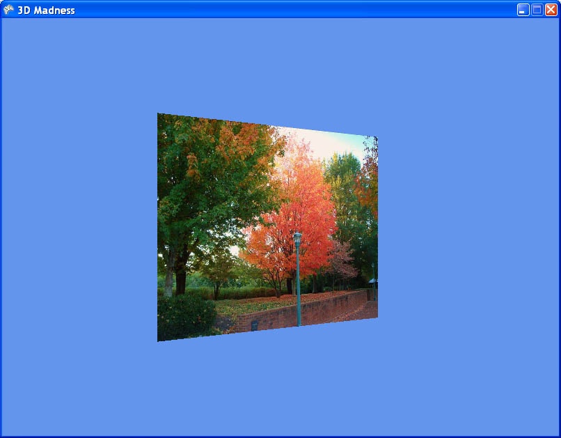
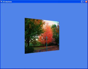
In this section, we’ll be using the source code for the textured rectangle project from Chapter 9. You might remember this project as the one that created the cool rectangle with a tree image texture. Running the project will result in the familiar tree rectangle that you saw back when you first started the 3D section (see Figure 13-2).
Currently, the rectangle is drawn using the BasicEffect class. You’re going to change that so it uses an effect created
from an HLSL file that you generate. The first thing to do is create a
subfolder under the 3DMadnessContent project in
your solution by right-clicking the
3DMadnessContent project in Solution Explorer and
selecting Add→New Folder. Name the new
folder Effects.
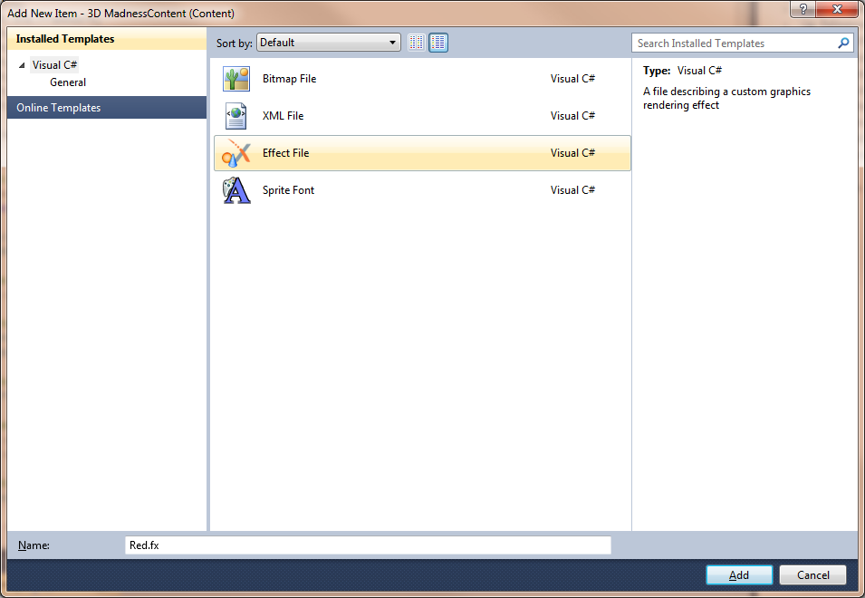
Next, right-click the 3DMadnessContentEffects folder in Solution Explorer and select Add→New Item…. Select Effect File as the template on the right and name the file Red.fx, as shown in Figure 13-3.
Odds are that your sample effect file is the same as the code listed previously, but with comments added for your benefit. Just to be safe, make sure that your effect file contains the following code:
float4x4 World;
float4x4 View;
float4x4 Projection;

// TODO: add effect parameters here.

struct VertexShaderInput
{
    float4 Position : POSITION0;

    // TODO: add input channels such as texture
    // coordinates and vertex colors here.
};

struct VertexShaderOutput
{
    float4 Position : POSITION0;

    // TODO: add vertex shader outputs such as colors and texture
    // coordinates here. These values will automatically be interpolated
    // over the triangle, and provided as input to your pixel shader.
};

VertexShaderOutput VertexShaderFunction(VertexShaderInput input)
{
    VertexShaderOutput output;

    float4 worldPosition = mul(input.Position, World);
    float4 viewPosition = mul(worldPosition, View);
    output.Position = mul(viewPosition, Projection);

    // TODO: add your vertex shader code here.

    return output;
}

float4 PixelShaderFunction(VertexShaderOutput input) : COLOR0
{
    // TODO: add your pixel shader code here.

    return float4(1, 0, 0, 1);
}

technique Technique1
{
    pass Pass1
    {
        // TODO: set renderstates here.

        VertexShader = compile vs_2_0 VertexShaderFunction();
        PixelShader = compile ps_2_0 PixelShaderFunction();
    }
}
You can verify that your effect code will compile by compiling your solution. If you get no compilation errors, you know that your code is at least syntactically correct (that’s a good sign).
To use your effect in code, you need to create a variable of type
Effect to store the effect in memory.
You already have an effect variable in your Game1
class, but currently it is of type BasicEffect.
Modify the declaration of the class-level effect variable in your
Game1 class to be of type Effect,
as shown here:
Effect effect;
Next, you’ll need to load the effect into your Effect object via the content pipeline. Remove
the following line from your LoadContent method,
which initialized your BasicEffect:
effect = new BasicEffect(GraphicsDevice);
and replace it with the following code, which loads your effect from the content pipeline:
effect = Content.Load<Effect>(@"effects
ed");
Finally, you’ll need to remove the following code in your Draw method, which uses the BasicEffect class to draw:
//Set object and camera info
effect.World = worldRotation * worldTranslation * worldRotation;
effect.View = camera.view;
effect.Projection = camera.projection;
effect.Texture = texture;
effect.TextureEnabled = true;

// Begin effect and draw for each pass
foreach (EffectPass pass in effect.CurrentTechnique.Passes)
{
    pass.Apply();

    GraphicsDevice.DrawUserPrimitives<VertexPositionTexture>
        (PrimitiveType.TriangleStrip, verts, 0, 2);

}
Tip
The second line of the code in this listing may be different in
your project. This was because at the end of Chapter 9, I encouraged you to try different
combinations of worldRotations and
worldTranslations in the setting of
the effect.World variable. Don’t
worry about that; just replace the preceding code section with the one
listed next.
Replace that code with the following code, which uses your new
Effect file instead of the BasicEffect class:
effect.CurrentTechnique = effect.Techniques["Technique1"];
effect.Parameters["World"].SetValue(Matrix.Identity);
effect.Parameters["View"].SetValue(camera.view);
effect.Parameters["Projection"].SetValue(camera.projection);

foreach (EffectPass pass in effect.CurrentTechnique.Passes)
{
    pass.Apply();
    GraphicsDevice.DrawUserPrimitives<VertexPositionTexture>
        (PrimitiveType.TriangleStrip, verts, 0, 2);
}
You’ll notice that the core drawing foreach loop used is the same: you’re looping through all the passes of
the current technique and drawing your object. The main difference in
the code lies in the fact that you are no longer using the BasicEffect class to draw.
The BasicEffect class
has several properties to which you assigned the object’s
world matrix, the camera’s view matrix, and the camera’s projection
matrix. When using HLSL, you still use that data, but you instead assign
it to the global variables mentioned in your HLSL effect file by using
the effect.Parameters[].SetValue
method.
If you’ve been playing with your code from Chapter 9 or tweaking it by following the
exercises in this book, your code might be somewhat different than what
I have used in this chapter thus far. To clarify, here’s what your
Game1 class should look like at this
point:
using System;
using System.Collections.Generic;
using System.Linq;
using Microsoft.Xna.Framework;
using Microsoft.Xna.Framework.Audio;
using Microsoft.Xna.Framework.Content;
using Microsoft.Xna.Framework.GamerServices;
using Microsoft.Xna.Framework.Graphics;
using Microsoft.Xna.Framework.Input;
using Microsoft.Xna.Framework.Media;

namespace _3D_Madness
{
    /// <summary>
    /// This is the main type for your game
    /// </summary>
    public class Game1 : Microsoft.Xna.Framework.Game
    {
        GraphicsDeviceManager graphics;
        SpriteBatch spriteBatch;

        // Game camera
        Camera camera;

        // Vertex data
        VertexPositionTexture[] verts;
        VertexBuffer vertexBuffer;

        // Effect
        Effect effect;

        // Movement and rotation stuff
        Matrix worldTranslation = Matrix.Identity;
        Matrix worldRotation = Matrix.Identity;

        // Texture info
        Texture2D texture;

        public Game1()
        {
            graphics = new GraphicsDeviceManager(this);
            Content.RootDirectory = "Content";
        }

        /// <summary>
        /// Allows the game to perform any initialization it needs to before
        /// starting to run. This is where it can query for any required services and
        /// load any non-graphic-related content.  Calling base.Initialize will
        /// enumerate through any components and initialize them as well.
        /// </summary>
        protected override void Initialize()
        {
            // Initialize camera
            camera = new Camera(this, new Vector3(0, 0, 5),
                Vector3.Zero, Vector3.Up);
            Components.Add(camera);

            base.Initialize();
        }

        /// <summary>
        /// LoadContent will be called once per game and is the place to load
        /// all of your content.
        /// </summary>
        protected override void LoadContent()
        {
            // Create a new SpriteBatch, which can be used to draw textures.
            spriteBatch = new SpriteBatch(GraphicsDevice);

            // Initialize vertices
            verts = new VertexPositionTexture[4];
            verts[0] = new VertexPositionTexture(
                new Vector3(-1, 1, 0), new Vector2(0, 0));
            verts[1] = new VertexPositionTexture(
                new Vector3(1, 1, 0), new Vector2(1, 0));
            verts[2] = new VertexPositionTexture(
                new Vector3(-1, -1, 0), new Vector2(0, 1));
            verts[3] = new VertexPositionTexture(
                new Vector3(1, -1, 0), new Vector2(1, 1));

            // Set vertex data in VertexBuffer
            vertexBuffer = new VertexBuffer(GraphicsDevice,
                typeof(VertexPositionTexture), verts.Length,
                BufferUsage.None);
            vertexBuffer.SetData(verts);

            // Load texture
            texture = Content.Load<Texture2D>(@"Textures	rees");

            // Load the effect
            effect = Content.Load<Effect>(@"effects
ed");
        }

        /// <summary>
        /// UnloadContent will be called once per game and is the place to unload
        /// all content.
        /// </summary>
        protected override void UnloadContent()
        {
            // TODO: Unload any non-ContentManager content here
        }

        /// <summary>
        /// Allows the game to run logic such as updating the world,
        /// checking for collisions, gathering input, and playing audio.
        /// </summary>
        /// <param name="gameTime">Provides a snapshot of timing values.</param>
        protected override void Update(GameTime gameTime)
        {
            // Allows the game to exit
            if (GamePad.GetState(PlayerIndex.One).Buttons.Back ==
                ButtonState.Pressed)
                this.Exit();            // Translation
            KeyboardState keyboardState = Keyboard.GetState();
            if (keyboardState.IsKeyDown(Keys.Left))
                worldTranslation *= Matrix.CreateTranslation(-.01f, 0, 0);
            if (keyboardState.IsKeyDown(Keys.Right))
                worldTranslation *= Matrix.CreateTranslation(.01f, 0, 0);

            // Rotation
            worldRotation *= Matrix.CreateFromYawPitchRoll(
                MathHelper.PiOver4 / 60,
                0,
                0);

            base.Update(gameTime);
        }

        /// <summary>
        /// This is called when the game should draw itself.
        /// </summary>
        /// <param name="gameTime">Provides a snapshot of timing values.</param>
        protected override void Draw(GameTime gameTime)
        {
            GraphicsDevice.Clear(Color.CornflowerBlue);


            // Set the vertex buffer on the GraphicsDevice
            GraphicsDevice.SetVertexBuffer(vertexBuffer);

            effect.CurrentTechnique = effect.Techniques["Technique1"];
            effect.Parameters["World"].SetValue(Matrix.Identity);
            effect.Parameters["View"].SetValue(camera.view);
            effect.Parameters["Projection"].SetValue(camera.projection);

            foreach (EffectPass pass in effect.CurrentTechnique.Passes)
            {
                pass.Apply();
                GraphicsDevice.DrawUserPrimitives<VertexPositionTexture>
                    (PrimitiveType.TriangleStrip, verts, 0, 2);
            }


            base.Draw(gameTime);
        }
    }
}
Compile and run the project, and you should see the same rectangle as before, but now in red (see Figure 13-4).

Now you may be thinking, “Hmmm…the rectangle looked way better
when I was using BasicEffect. HLSL is
lame!” I have to admit that the rectangle did look better before, but
this is only the very beginning of what HLSL can do. Let’s take a look
at some more detailed HLSL code to see if we can make things any
better.
Applying HLSL Using Textures
Coloring a rectangle red requires only the simplest HLSL shader, and it’s something you’ll rarely find in the latest video games. Typically, you’ll be applying a texture to an object and then tweaking the way the texture appears by applying shininess or fog or some other effect.
In this section, you’ll apply a custom HLSL file to your rectangle while applying color from the trees texture as well.
Open your Red.fx file again and replace the code in the file with the code shown here:
float4x4 xWorldViewProjection;

Texture xColoredTexture;

sampler ColoredTextureSampler = sampler_state
{ texture = <xColoredTexture> ;
magfilter = LINEAR; minfilter = LINEAR; mipfilter=LINEAR;
AddressU = mirror; AddressV = mirror;};struct VertexIn
{
    float4 position : POSITION;
    float2 textureCoordinates : TEXCOORD0;
};

struct VertexOut
{
    float4 Position : POSITION;
    float2 textureCoordinates : TEXCOORD0;
};

VertexOut VertexShaderFunction(VertexIn input)
{
    VertexOut Output = (VertexOut)0;
    Output.Position =mul(input.position, xWorldViewProjection);
    Output.textureCoordinates = input.textureCoordinates;

    return Output;
}

float4 PixelShaderFunction(VertexOut input) : COLOR0
{
    float4 output = tex2D(ColoredTextureSampler,
        input.textureCoordinates);
    return output;
}

technique Textured
{
    pass Pass0
    {
        VertexShader = compile vs_2_0 VertexShaderFunction(  );
        PixelShader = compile ps_2_0 PixelShaderFunction(  );
    }
}
Even though you’re still new to HLSL, this file isn’t incredibly
complex, and for the most part it should make sense to you. Notice first
that instead of using three variables to represent the world, view, and
projection matrices, respectively, you have only one variable, called xWorldViewProjection. In your XNA code, you’ll
need to multiply the world, view,
and projection matrices together and assign the resulting value to
this variable. Because they are
all multiplied together to set the vertex position, it doesn’t matter
whether you do that in the HLSL file or in XNA code. The advantage of
doing the multiplication in XNA code rather than in the HLSL file is
that you do the multiplication once per scene if you pass it into the
HLSL code, whereas doing the
multiplication within HLSL will cause it to be done once for
every vertex.
Also, notice the new variable called xColoredTexture. This variable represents a
texture object, and you’ll need to assign it the value of your Texture object from your XNA code.
There’s also a ColoredTextureSampler object that allows you
to sample data from a texture to determine the color of a particular
part of that texture. When the pixel shader runs, it will map each pixel
on the object to the corresponding location in the texture by using the
sampler object and will return the color that the pixel should
have.
Notice that the pixel shader uses a tex2D method to accomplish this. tex2D is a function that is built into HLSL,
much like mul, which you used
previously to multiply together two matrices. tex2D looks up a color at a particular point
in a texture using a sampler. Essentially, you’ll be running your pixel
shader for every pixel on the screen, right? Each time the pixel shader
runs, you’re going to receive a texture coordinate for that pixel (it’s
passed into the pixel shader via the textureCoordinates member of the VertexOut struct). The
tex2D function will take those
texture coordinates, look up the corresponding pixel in the texture at
each coordinate, and return the color of that pixel. Using this method,
the entire rectangle will be colored to look just like the texture
you’re passing to the HLSL effect file.
In addition to mul and tex2D, there are a number of other built-in
functions (also called intrinsic functions) in HLSL. These functions are
listed in Microsoft’s MSDN library for help on DirectX and XNA. For your
convenience, they are also shown in Table 13-5.
Syntax | Description |
Returns the absolute value (per component) | |
Returns the arccosine of
each component of | |
Tests if all components
of | |
Tests if any component of
| |
Converts the input type to a float | |
Returns the arcsine of
each component of | |
Converts the input type to an integer | |
Converts the input type to an unsigned integer | |
Returns the arctangent of
| |
Returns the arctangent of
two values ( | |
Returns the smallest
integer that is greater than or equal to | |
Clamps | |
Discards the current
pixel, if any component of | |
Returns the cosine of
| |
Returns the hyperbolic
cosine of | |
Returns the cross product of two 3D vectors | |
Swizzles and scales
components of the 4D vector | |
Returns the partial
derivative of | |
Returns the partial
derivative of | |
Converts | |
Returns the determinant
of the square matrix | |
Returns the distance between two points | |
Returns the dot product of two vectors | |
Returns the base-e exponent | |
Returns the base-2 exponent (per component) | |
Returns | |
Returns the greatest
integer that is less than or equal to | |
Returns the
floating-point remainder of | |
Returns the fractional
part of | |
Returns the mantissa and
exponent of | |
Returns | |
Returns the number of render-target samples | |
Returns a sample position (x, y) for a given sample index | |
Returns | |
Returns | |
Returns | |
Returns | |
Returns the length of the
vector | |
Returns | |
Returns a lighting vector (ambient, diffuse, specular, 1) | |
Returns the base-e
logarithm of | |
Returns the base-10
logarithm of | |
Returns the base-2
logarithm of | |
Selects the greater of
| |
Selects the lesser of
| |
Splits the value | |
Performs matrix
multiplication using | |
Generates a random value using the Perlin-noise algorithm | |
Returns a normalized vector | |
Returns | |
Converts | |
Returns a reflection vector | |
Returns the refraction vector | |
Rounds | |
Returns | |
Clamps | |
Computes the sign of
| |
Returns the sine of
| |
Returns the sine and
cosine of | |
Returns the hyperbolic
sine of | |
Returns a smooth Hermite interpolation between 0 and 1 | |
Returns the square root (per component) | |
Returns | |
Returns the tangent of
| |
Returns the hyperbolic
tangent of | |
1D texture lookup | |
1D texture lookup with bias | |
1D texture lookup with a gradient | |
1D texture lookup with LOD | |
1D texture lookup with projective divide | |
2D texture lookup | |
2D texture lookup with bias | |
2D texture lookup with a gradient | |
2D texture lookup with LOD | |
2D texture lookup with projective divide | |
3D texture lookup | |
3D texture lookup with bias | |
3D texture lookup with a gradient | |
3D texture lookup with LOD | |
3D texture lookup with projective divide | |
Cube texture lookup | |
Cube texture lookup with bias | |
Cube texture lookup with a gradient | |
| Cube texture lookup with LOD |
Cube texture lookup with projective divide | |
Returns the transpose of
the matrix | |
Truncates floating-point value(s) to integer value(s) |
So essentially, the new effect file that you’ve just created is going to set the vertex positions and then color the object by pulling pixel coordinates out of the associated texture using the sampler object. In other words, it will map the texture to the rectangle drawn on the screen.
Next, you’ll need to change the code in your Draw method to use your new custom effect
rather than the red custom effect used previously. Do you remember what
data you need to set in order to use an HLSL effect in XNA?
You’ll need to set the name of the effect to run, and you’ll need
to set all global variables in the effect file. Currently, you have the
following code in the Draw method of
your Game1 class to do that, but
you’re setting data for the red.fx file:
effect.CurrentTechnique = effect.Techniques["Technique1"];
effect.Parameters["World"].SetValue(Matrix.Identity);
effect.Parameters["View"].SetValue(camera.View);
effect.Parameters["Projection"].SetValue(camera.Projection);
The first thing you’ll need to change in order to use the new
effect is the name of the technique. The technique in the
red.fx file was called Technique1, whereas the new effect uses a
technique called Textured.
Change the first line of the preceding code, which is in the
Draw method of your Game1 class, to this:
effect.CurrentTechnique = effect.Techniques["Textured"];
Next, you might have noticed that the global variables are
different. Previously, you had three global variables in your HLSL
effect: World, View, and Projection.
Your new effect has only two global variables: xWorldViewProjection (which should be set to
the world matrix multiplied by the view matrix multiplied by the
projection matrix) and xColoredTexture (which should be set to the
Texture2D object you want to apply to
the rectangle).
Remove the following three lines of code from the Draw method of your Game1 class:
effect.Parameters["World"].SetValue(Matrix.Identity);
effect.Parameters["View"].SetValue(camera.View);
effect.Parameters["Projection"].SetValue(camera.Projection);
and replace them with this code:
effect.Parameters["xWorldViewProjection"].SetValue(
    Matrix.Identity * camera.view * camera.projection);
effect.Parameters["xColoredTexture"].SetValue(texture);
This new code should look pretty familiar because it’s essentially
the same as the code you added in the previous example to make your
triangle draw in red. The only key difference here is that, as mentioned
previously, you are setting the World, View, and Projection variables all at once rather than
individually. When multiplied together, they give you the same result,
so this works just as well as the method you used earlier.
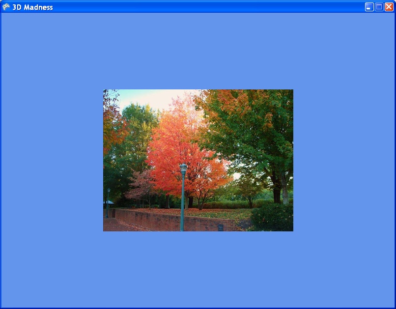
Compile and run the game now, and you’ll see the exact same textured rectangle, but this time it will be rendered using a custom HLSL shader (as seen in Figure 13-5).
One thing that you’ve probably noticed is that your rectangle used to spin, but now it stands still. Why is that? The answer lies in the world matrix. Remember that an object’s world matrix represents the position, rotation, scale, and so on for that particular object. Therefore, if the object isn’t rotating properly, isn’t scaled correctly, or is in the wrong location, there’s probably a problem with the object’s world matrix.
In this particular case, you’re supposed to set the xWorldViewProjection HLSL variable to the
world matrix multiplied by the view matrix multiplied by the projection
matrix. The code you used to do that is listed here:
effect.Parameters["xWorldViewProjection"].SetValue(
    Matrix.Identity * camera.view * camera.projection);
Notice the value that you’re using for the world portion of that
multiplication: Matrix.Identity.
Remember what the identity matrix does? When you multiply matrix A by
the identity matrix, the product is matrix A. So in this case, you’re
multiplying the identity matrix by the view and the projection. That’s
exactly the same as just multiplying together the view and the
projection; in other words, you’re really not specifying anything
special (no movement, no rotations, nothing) for the object’s world
matrix. That’s why the object isn’t rotating.
So, how do you fix that? When you built this code in Chapter 9, you used two class-level matrix
variables to rotate the rectangle: worldTranslation and worldRotation. To make the object rotate, build a world matrix from
the worldTranslation and worldRotation matrices, and use that world
matrix instead of Matrix.Identity
when setting the xWorldViewProjection
HLSL variable.
That is, replace the following line in the Draw method of your Game1 class:
effect.Parameters["xWorldViewProjection"].SetValue(
    Matrix.Identity * camera.view * camera.projection);
with this:
Matrix world = worldRotation * worldTranslation;
effect.Parameters["xWorldViewProjection"].SetValue(
    world * camera.view * camera.projection);
Now the rotation and translation code you wrote in Chapter 9 will be applied to the rectangle. Run the game at this point and you should see a spinning rectangle, as shown in Figure 13-6.
The rectangle will move when you press the left and right arrow
keys, just as you coded the original rectangle to do in Chapter 9. Again, feel free to play with the
different rotations and translations and apply them in different orders,
as you did in Chapter 9. Instead of setting
the World property of the BasicEffect class, you’re now creating a
temporary world matrix variable and assigning that value to the variable
in an HLSL effect file, but the end result is exactly the same.
Well…maybe HLSL isn’t so amazing. You just put in a lot of extra work to end up with the exact same result that you had previously! That’s not the end of the possibilities, though. Let’s look at some different things you can do with this textured rectangle using HLSL.
HLSL Effects: Creating a Negative
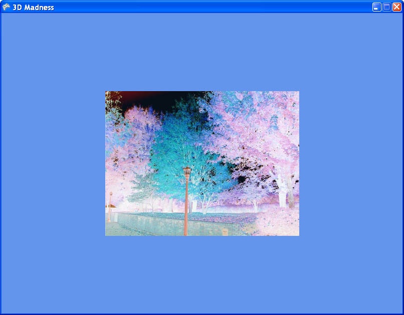
Now that you have an effect file using a texture, there are any number of things you can do to your HLSL file to get some really interesting and cool effects. For instance, changing the code in the pixel shader to the following will result in a negative image being drawn:
float4 PixelShaderFunction(VertexOut input) : COLOR0
{
    float4 output = 1-tex2D(ColoredTextureSampler, input.textureCoordinates);
    return output;
}
The effect is shown in Figure 13-7.
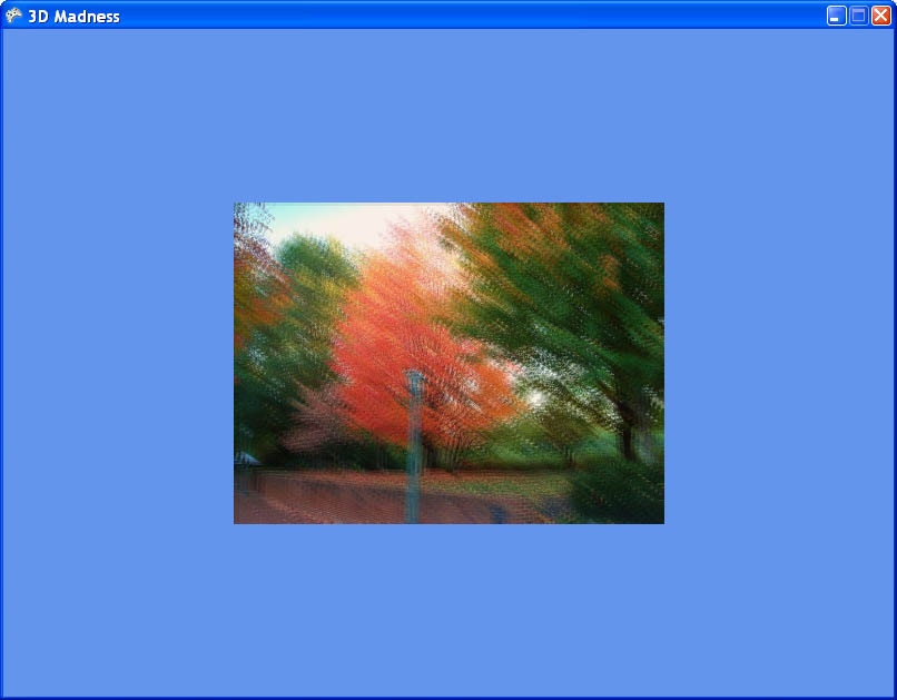
HLSL Effects: Blur
Another very simple effect is blurring the image. To do this, you grab the color of each pixel in the texture and add to it the colors from the pixels adjacent to the target pixel. To try this, replace the pixel shader in your game with the following code:
float4 PixelShaderFunction(VertexOut input) : COLOR0
{
    float4 Color;
    Color =  tex2D(ColoredTextureSampler, input.textureCoordinates.xy);
    Color += tex2D(ColoredTextureSampler, input.textureCoordinates.xy + (0.01));
    Color += tex2D(ColoredTextureSampler, input.textureCoordinates.xy - (0.01));
    Color = Color / 3;

    return Color;
}
The result will be a blurred image, as shown in Figure 13-8.
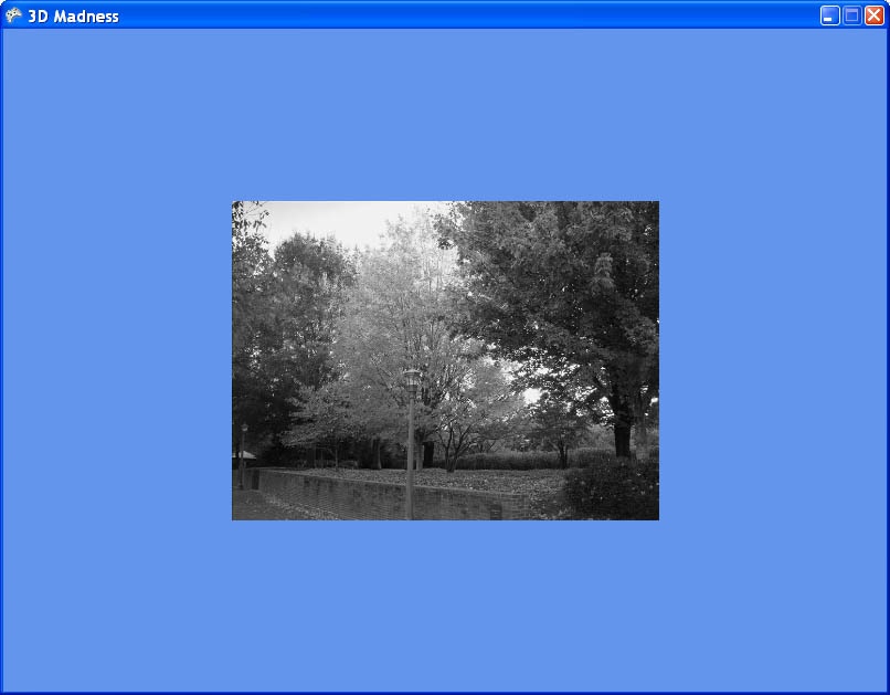
HLSL Effects: Grayscale
Rendering an image in grayscale is another very simple effect that can be added with little difficulty. By applying a standard grayscale equation, you can convert the colors of every pixel to a shade of gray using the dot function. Replace your pixel shader with this code:
float4 PixelShaderFunction(VertexOut input) : COLOR0
{
    float4 color;
    color = tex2D( ColoredTextureSampler, input.textureCoordinates.xy);
    return dot(color, float3(0.3, 0.59, 0.11));
}
What’s this doing? First, the shader function retrieves the color of the pixel at the coordinate of the pixel. Then, the dot function retrieves a dot product using two vectors: the color of the pixel from the texture and a vector generated using (0.3, 0.59, 0.11). Why these numbers? Well, you could just use 0.33 for each of them and get an average color, which would look pretty decent in grayscale. However, a long time ago, somebody much smarter than myself figured out that these numbers much more closely approximate grayscale as seen by the human eye. I hate to quote Wikipedia in a book like this, but it’s a great resource to read about these numbers (see http://en.wikipedia.org/wiki/Grayscale).
The resulting image will be drawn in grayscale, as shown in Figure 13-9.
As you can see, there are endless possibilities when dealing with HLSL effects. These are only a few samples of the things you can do. As mentioned at the beginning of this chapter, this book isn’t intended to be a definitive resource on HLSL. However, if this stuff interests you, there are a lot of resources on the Internet and other books that will take you deeper into the world of HLSL and effects.
What You Just Did
In the next chapter, we’ll look at particle engines and how you can apply HLSL to particles to make them look realistic. But before we get to that, let’s take a look back at this chapter and what you just did:
You learned about HLSL syntax, including semantics, keywords, functions, vertex shaders, and pixel shaders.
You implemented your first shader, which colored everything drawn on the screen in red.
You implemented a texture map shader that colored a rectangle based on pixel coordinates in a texture.
You created several different effects using HLSL.
Summary
HLSL allows developers to make full use of the wide range of capabilities of the latest graphics cards.
In HLSL, there are two kinds of shaders: vertex shaders (which are executed once for each visible vertex in the scene) and pixel shaders (which are executed once for each pixel drawn in the scene).
The minimum requirement of a vertex shader is to set the position of each vertex. The minimum requirement of a pixel shader is to set the color of each pixel.
In HLSL, data is run first through the vertex shader, then through a rasterization process, and then through a pixel shader before finally being sent to the screen.
HLSL files are added to the project in the Content folder and are picked up by the content pipeline. The content pipeline compiles them, and any syntax errors will be caught at compile time.
Pixel shader 2.0 can draw most objects, but pixel shader 928,217,661,293,721.12 is required to draw either of Chuck Norris’s biceps.
Test Your Knowledge: Quiz
In HLSL, how can you access the first element in a
float4object?What is swizzling?
In HLSL, how do you specify which vertex and pixel shader versions to use?
What does HLSL do for you that you can’t accomplish without it?
How do you multiply two matrices together in HLSL?
What is the role of a semantic in HLSL?
Who burninates the countryside, burninates the peasants, burninates all the people, and their thatch-roofed cottages?
Test Your Knowledge: Exercise
Take the code you built in this chapter and draw a six-sided cube using the trees image provided as the texture for each side of the cube. On each side of the cube, use one of the four texture effects you built in this chapter (normal texture, burred texture, negative texture, grayscale texture). Use each of the four effects at least once on the cube.