
Now that we know how to load resources, we can get on with the fun stuff. We're going to look at how we can draw a bitmapped image on screen.
We've already seen how to do this in the "Hello World" project of Chapter 1, Getting Started with Marmalade. We just call IwGxInit to set up IwGx at the start of our program and IwGxTerminate to close it down again at the end.
In IwGx, the most commonly used polygon types are lines, triangles, and quads (basically two triangles that share a common edge).
Also supported are sprites, which are always rectangular in shape and do not allow any scaling of textures, and n-polys, which can contain up to 63 vertices.
Sprites are rarely used since triangles and quads are more flexible, though they can be faster to draw especially in software rendering mode. The n-poly can also be faster to draw for the software renderer than a series of triangles, but they are generally best avoided since they need to be converted into triangles on the fly in order to be drawn using hardware rendering.
To render a polygon on screen, we at least need to specify where we want it to appear on screen and what color we want it to be in. Additionally, we might want to draw the polygon using a bitmapped image. The following sections show how we can provide this information.
First we let IwGx know what color (or indeed colors) and image we want applied to our polygon. We do this by specifying the material we want to use, which is an instance of the CIwMaterial class that groups together this information. To set the material we want to use, we must provide IwGx with a pointer to the relevant CIwMaterial instance using the following function call:
IwGxSetMaterial(pMaterial);
If we are drawing a polygon with no image applied to it, then the very minimum information the material will need to provide is the color we want to use.
A material actually contains four different colors that, if you are at all familiar with 3D graphics rendering, you will probably recognize. They are the ambient, diffuse, emissive, and specular colors. For 2D rendering purposes, it is only the ambient color that we are concerned with. We'll look into the others when we move on to 3D rendering in Chapter 4, 3D Graphics Rendering.
The material
also specifies the texture we want to apply. A texture specifies a bitmapped image that we want to apply to our polygon, and is represented in Marmalade by the CIwTexture class.
The CIwTexture class is actually a wrapper for the CIwImage class that actually stores the pixel information for an image. CIwTexture adds functionality to control how the image is actually rendered, with support for enabling and disabling features such as bilinear filtering and mipmapping.
Materials also provide control over other polygon rendering features, such as whether the polygon is rendered flat or gouraud shaded, and how it should be blended with the current screen contents when it is drawn.
Materials can either be created in code or they can be instanced by the resource manager. The following sections illustrate this.
Creating a material
in code requires little more than making a new instance of CIwMaterial and using the available methods to set the color, textures, and other settings. For example, to create a material that will render bright red, semi-transparent polygons we could use the following code:
CIwMaterial* lpRedMaterial = new CIwMaterial;
lpRedMaterial->SetColAmbient(255, 0, 0, 128);
lpRedMaterial->SetAlphaMode(CIwMaterial::ALPHA_BLEND);
Note that Marmalade will raise an assert message if you try to create a local CIwMaterial instance on the program stack. This happens because rendering does not happen the moment you make a drawing function call, so by the time rendering does occur, the material data will likely have been trashed by other functions reusing the same area of stack space.
While creating materials in code is simple enough, there is an easier way, especially when it comes to specifying materials with textures. This involves yet another use of our friend, the ITX file.
A material file has the extension .mtl and again uses the same formatting rules as an ITX file. We can create any number of CIwMaterial instances in an MTL file and initialize them with the required colors, textures, and other settings.
As a bonus, any texture we refer to in the MTL file will also be loaded automatically, meaning we don't have to list it separately in a GROUP file. In order for this to work, all the source image files must reside in a subdirectory named textures, which is located in the same directory as the MTL file, or alternatively they must already have been loaded into memory either from another GROUP file or in the same GROUP file prior to referencing the MTL file.
Here is an example of what an MTL file might look like:
CIwMaterial
{
  name      "red"
  colAmbient  { 255 0 0 128 }
  alphaMode    BLEND
}

CIwMaterial
{
  name      "grid"
  colAmbient  { 128 128 128 128 }
  texture0    "grid.png"
  alphaMode    ADD
  shadeMode    FLAT
  filtering    false
}
This example generates a semi-transparent red material equivalent to that created in the previous section, and also a material using a texture named grid.png, which is drawn flat shaded with additive transparency at half the original image brightness and without bilinear filtering.
Note
You may have noticed that the image is specified using an attribute called texture0. Marmalade materials can actually be assigned two textures that can be blended together when rendering a polygon and they are referred to as texture0 and texture1. In this book we will only be concerned with single texture materials.
There are
far too many attribute names to list here, so for a complete list take a look at the Marmalade documentation page for the CIwMaterial class. This page lists all of them.
To make these materials available in our code, we just need to reference the MTL file inside a GROUP file that we are loading. We can then get hold of the materials by searching for them by name using the resource manager functions described earlier in this chapter.
Note
It is recommended that when materials are created using an MTL file, you do not modify any of their settings using the methods in the CIwMaterial class. Instead, make a copy of the material using the CIwMaterial::Copy method. While it is possible to do so, problems can occur if the same material is used to render several different things, since rendering does not occur as soon as a drawing function call is made. The end result is therefore unpredictable as it would depend on how the CIwMaterial happens to be configured when rendering finally occurs.
In order to display a polygon on screen, we need to specify a list of screen coordinates that define the corner points. Since we are only rendering in 2D at the moment, each coordinate is specified as a CIwSVec2 instance, which is a vector class defined in another Marmalade API called IwGeom. Any list of data items used when rendering polygons, be it vertices, colors, or whatever, is often referred to as a
stream, so a list of vertices is called a
vertex stream.
While we can specify this API to be part of our project by adding iwgeom to the subprojects section of the MKB file and calling IwGeomInit and IwGeomTerminate, there isn't actually a need to, since IwGx relies on this API itself.
The CIwSVec2 class defines a two-component vector using signed 16-bit integers, so it is perfect for specifying screen coordinates.
The default screen coordinate system in IwGx places the origin at the top-left corner of the screen, with the x component increasing horizontally to the right and the y component increasing vertically downwards. It is possible to change the position of the origin, however, by passing a CIwSVec2 instance containing the desired position of the origin to the function IwGxSetScreenSpaceOrg.
The following diagram illustrates how we could specify the coordinates for a triangle on a standard iPhone resolution screen (320 x 480 pixels). The top left of the screen is the origin and has a coordinate position of (0,0), while the bottom-right corner has a position of (320,480).
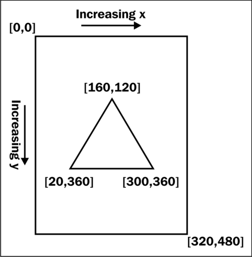
To render this
triangle all we have to do is fill in an array of CIwSVec2 with the coordinates and submit them to IwGx, as follows:
CIwSVec2* v = new CIwSVec2[3];
v[0].x = 160;    v[0].y = 120;
v[1].x = 20;     v[1].y = 360;
v[2].x = 300;    v[2].y = 360;
IwGxSetVertStreamScreenSpace(v, 3);
The function call, IwGxSetVertStreamScreenSpace, allows us to specify a list of screen space (that is, pixel) coordinates we want to use for rendering, but we must also explicitly state how many vertices we are submitting. In the case of our triangle, this is three.
It is also possible to specify our coordinates using sub-pixel positioning with the function call IwGxSetVertStreamScreenSpaceSubPixel. It may be getting a bit on the long side to type, but using sub-pixel positioning does provide the advantage of smoother movement on
screen, as we are no longer limited to only moving things around the screen in terms of whole pixels.
Using sub-pixel coordinates can also improve the quality of the final rendered image, as slow moving objects won't appear to jump between pixel positions if we are rendering using bilinear filtering.
IwGx only supports eight sub-pixel positions per pixel; so to convert our coordinates to use sub-pixel positioning, all we need to do is multiply the screen coordinates by eight or use the bitwise shift operator to shift left by three places.
If we want to draw a polygon using flat shading, so that every pixel rendered is the same color, we can just set the ambient color of our material and our work is done.
However, if we want to render a polygon using gouraud shading, we need to specify a color to be used at each vertex. This can't be done with a material, so we need to override the material's color information by providing our own color stream.
We do this by creating an array of CIwColour objects, which is Marmalade's chosen method of representing a color. This class has four public member variables of type uint8 (an unsigned byte) called r, g, b, and a, which (probably not surprisingly) represent the red, green, blue, and alpha values of a color.
CIwColour also provide several methods to make setting and manipulating colors easier.
Returning to the triangle defined in the earlier diagram, if we wanted to color the top of it red, the bottom-right corner green, and the bottom-left corner blue, we can use the following code:
CIwColour* c = new CIwColour[3];
c[0].Set(255, 0, 0, 255);
c[1].Set(0 255, 0, 255);
c[2].Set(0, 0, 255, 255);
IwGxSetColStream(c);
Note
that IwGxSetColStream does not require us to specify the number of colors in our stream. This is because IwGx expects to find the same number of colors as there are vertices. If we do not want to specify a color stream, we can just pass NULL into the IwGxSetColStream function and the selected material's colors will be used instead.
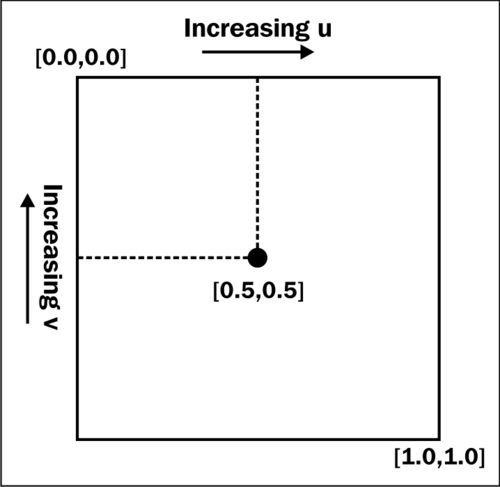
When rendering a polygon with a texture, we need to somehow indicate how that texture should be mapped to the polygon. We do this by specifying a UV stream that allows us to state which part of the texture should appear at each vertex. The part of the texture required for each rendered pixel can then be worked out by the rendering engine by interpolating the UV values across the surface of the polygon.
In IwGx, UV coordinates are specified using floating point numbers. An individual UV value is often written as (u, v) and is represented in IwGx using the CIwFVec2 class, which is a floating point equivalent of CIwSVec2 that we came across earlier. The x component of the vector represents u, and the y component represents v.
UV values are mapped to a texture so that (0.0, 0.0) is the top left of the image and (1.0, 1.0) is the bottom-right corner. We can repeatedly tile a texture up to a maximum of eight times across our polygon by using values larger than one.
Note
Prior to Marmalade version 6.1, UV values were given as 16-bit signed integers using a 12-bit fixed point representation. The value 4096 is equivalent to 1.0, 8192 is equivalent to 2.0, and 2048 is equivalent to 0.5. The IwGeom API provides us with the define IW_GEOM_ONE, which we can use to avoid having nasty-looking magic numbers throughout our code. This functionality can still be used by reverting to the legacy version of the IwGx API, as detailed earlier in this chapter.
By mapping UV values in this way, we make them independent of the actual size of the texture image. If we change the size of the image for any reason, it won't mess up rendering as our UV values do not need to change.
As with vertex streams, all we have to do to specify a set of UV values is allocate an array of CIwSVec2, populate the array, and submit it to IwGx. We don't need to specify the number of UV values we are submitting, as IwGx expects to see the same number of UVs as there are vertices. Here is some sample code that we might want to use to apply a texture to a triangle:
CIwSVec2* uv = new CIwSVec2[3];
uv[0].x = IW_GEOM_ONE / 2;    uv[0].y = 0;
uv[1].x = 0;                  uv[1].y = IW_GEOM_ONE;
uv[2].x = IW_GEOM_ONE;        uv[2].y = IW_GEOM_ONE;
IwGxSetUVStream(uv, 0);
The second
parameter of IwGxSetUVStream indicates which texture the UV values apply to. If the material we are using only has a single texture, we can just leave this parameter out entirely as it will default to 0, but if the material does have a second texture, we need to supply a UV stream to be used with it by changing the second parameter of IwGxSetUVStream to 1. This UV stream could be the same as the stream for the first texture or it could be a completely different set of UV values.
If our material does not have a texture applied to it, there is no need to set the UV stream to NULL as it will be ignored completely.
We've now seen how to set just about all the information we need to specify how we want our polygon to appear, so we can finally instruct IwGx to draw it. To do so, we need to let IwGx know how our various input streams should be interpreted by using the following function call:
IwGxDrawPrims(polygon_type, indices, num_indices);
The polygon_type parameter indicates whether we are drawing triangles, quads, lines, sprites, or n-polys, while the indices parameter is an array of uint16 values showing the order in which the elements of our input streams should be accessed. This is called an
index stream. The num_indices parameter is just a count of how many elements are in the indices array.
The following diagram shows the types of polygons supported by IwGx. Note that it is possible to draw more than one polygon at a time by providing longer streams of data. This is something we should try to do as much as possible, since it prevents the GPU from idling while it is waiting to be supplied with new polygon information.
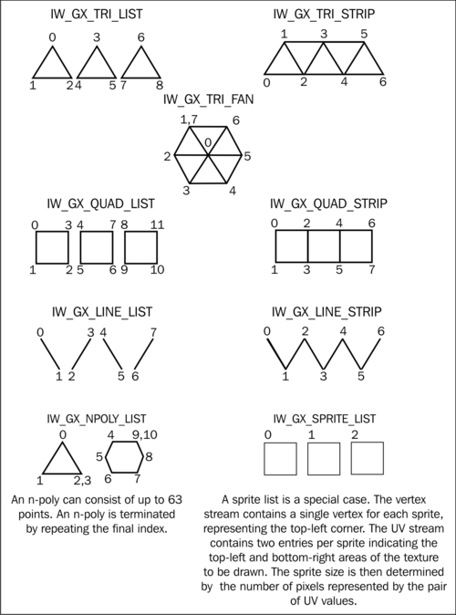
The numbers labeling the vertices in the diagram correspond to the elements of the index stream. When rendering, the indices array is traversed in the order shown for each polygon type, and the values it contains indicate which element of the various input streams should be used to render each vertex.
To draw the triangle we've been building up to, we can use the following code snippet:
uint16* indices = new uint16[3];
indices[0] = 0;  indices[1] = 1;  indices[2] = 2;
IwGxDrawPrims(IW_GX_TRI_STRIP, indices, 3);
We could simplify this a little more as the index stream isn't actually necessary in this instance since our input streams are accessed one element at a time in the order they occur in the stream, so we can just specify NULL for the indices parameter like this:
IwGxDrawPrims(IW_GX_TRI_STRIP, NULL, 3);
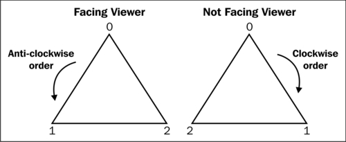
When creating the index stream there is one other point to bear in mind, which is the order in which we supply our vertices. Because IwGx can also be used to render 3D polygons on screen, it supports back face culling, which prevents any polygon that is facing away from the viewer from being rendered.
How is a polygon classified as facing toward or away from the viewer? If we label each vertex of a polygon with an incrementing number, starting with zero for the first vertex and following around the edges of the polygon from vertex to vertex, then a polygon is facing the viewer if its vertices form an anti-clockwise pattern when rendered on screen and considered in ascending numerical order. The order the vertices are supplied in is called the winding order, and the following diagram shows this more clearly:
Putting the vertices in the correct order is not the only way to solve this problem, but it is worth getting in the habit of ordering the vertices in this way for when we progress to rendering 3D polygons. We can disable or reverse the back face culling operation on a per material basis by calling the CIwMaterial::SetCullMode method with one of the following enumeration values: CULL_FRONT, CULL_BACK, or CULL_NONE. The default is CULL_BACK.
Our polygon information has now been submitted for rendering; but we won't see it appear on screen just yet.
The final step in making something appear on screen is to flush all the drawing requests to the screen, and then display the final image.
IwGx automatically provides us with a double-buffered display setup. All this means is we do all our rendering to an off-screen buffer and then switch to displaying this buffer when all the drawing is complete. If we did not do this, we would likely see an incomplete, flickering screen display as our graphics could be displayed in an incomplete state if we drew straight to the visible display.
To complete the cycle of drawing, all we have to do is add the following two lines of code:
IwGxFlush();
IwGxSwapBuffers();
That's it! We've drawn our first polygon!