Continuum Models
Abstract
In this chapter, we aim to develop a new van der Waals interaction model for not only the postbuckling pressure but also the prebuckling pressure between any two layers of a multiwalled carbon nanotube (MWCNT). The formulas derived herein account for the dependence of the van der Waals interaction (before and after buckling) not only on the change of interlayer spacing but also on the tube radius. Hence, it is a better model and can be applied to the MWCNTs. Based on the derived formulas of van der Waals interaction, a continuum cylindrical shell model is presented to study the buckling of an MWCNT. Donnell’s shell model is applied to study the vibration of an MWCNT. The main objective is to predict the influence of the van der Waals interaction on the vibration of MWCNTs for various radii and number of layers. The numerical simulations show that the van der Waals interaction has very small influence on the fundamental natural frequency, but plays a significant role in all higher radial-dominated natural frequencies. Especially, due to the effect of van der Waals interaction, there exists a change over from radial mode to longitudinal mode or from longitudinal mode to torsional mode, for MWCNT in which the innermost radius of the CNT is very small.
Keywords
Van der Waals interaction; prebuckling; postbuckling; cylindrical shell model; Donnell’s shell model
6.1 Introduction
Carbon nanotubes (CNTs) exhibit superior mechanical properties and hold substantial promise as a class of materials by providing strong, light, and high toughness characteristics. Due to their superior properties, CNTs are particularly attractive for structural elements in nanoscale devices. Much research has been carried out on CNTs since their first discovery in 1991 by Iijima of the NEC Laboratory in Tsukuba, Japan [1]. In this research activity, atomistic-based methods such as classical molecular dynamics (MD) [2–4], tight-binding MD [5], and density functional theory [6] have been used to study single-walled CNTs (SWCNTs) or multiwalled CNTs (MWCNTs) under axial compression, axial tension, bending, and torsion deformation. However, the computational time and effort needed for these methods limited the size of MWCNTs studied. For example, in our MD simulation [7] of buckling behavior, the calculation for a (10, 10) SWCNT with 2000 atoms would have required 36 h computational time on the SGI Origin 2000 system. The computational time increases as the number of atoms increases, and thus the computational time explodes exponentially for MWCNTs. In another example, for an MWCNT under tension [8], a four-walled (5, 5), (10, 10), (15, 15), and (20, 20) CNT with length-to-diameter ratio L/D=9.1 contains 15097 atoms, and the calculation for the elasto-plastic deformation up to failure of CNT took up over 2 months on the SGI Origin 3000 system. Therefore, researchers have been seeking more efficient computational methods with which to analyze MWCNTs.
It was reported in the literature that continuum structural models might be applicable for the analysis of CNTs. In recent years, many continuum structural models have been proposed. Govindjee and Sackman [9] applied the Bernoulli–Euler beam-bending theory to examine Young’s modulus of an MWCNT. A space truss/frame model was developed by Li and Chou [10,11] for modeling an SWCNT, and Young’s modulus and shear modulus of an SWCNT were examined using their proposed model. Odegard et al. [12] proposed a truss model and an equivalent-plate model as a link between computational chemistry and solid mechanics. The proposed model was directly applied to predict the mechanical behavior of an SWCNT. Yakobson et al. [3] used a traditional continuum shell model to predict the buckling of an SWCNT, and compared it with the MD simulation. Their results show that the continuum shell model can obtain the buckling pattern. Pantano et al. [13] proposed a finite element approach to model the structure and deformation of SWCNTs and MWCNTs. Large bending deformation of MWCNTs was carried out in their work. However, to ensure that the shell theory is applicable to the analysis of CNTs, different estimates for the combination of Young’s modulus, effective wall thickness, and Poisson ratio have to be tested by comparing MD simulation with the finite element approach.
The classical cylindrical shell model was also used in the buckling and postbuckling analysis of MWCNTs. For the study of MWCNT, a proper representation of the vdW forces is critical to establish a continuum model. Liu et al. [14] developed a nanoscale finite element method for the multiscale simulation of CNT. The vdW force between layers is modeled as nonlinear spring elements. By modeling the vdW interaction as truss rods, Li and Chou [10] simulated the elastic properties of MWCNT by using an equivalent space framelike structure model and the finite element method. Ru [15–19] proposed a continuum shell model considering vdW interaction to study the buckling of double-walled CNTs (DWCNTs). He suggested a linear proportional relationship between the variation of the vdW force and the normal deflection to model the vdW forces, and obtained a simple relationship for the vdW interaction coefficient, c=(200 ergs/cm2)/(0.16d2), where d=0.142 nm. This relationship cannot reflect the effect of the radius of the CNT on the vdW interaction coefficient. In addition, he did not discuss the influence of the ignorance of the terms related to the ratio of (RO−RI)/RI on the buckling load, and concluded that the vdW forces do not increase the critical axial strain for infinitesimal buckling of DWCNTs. Wang et al. [20] extended Ru’s vdW interaction model to the buckling analysis of MWCNTs, but Ru’s model can only be applied to the interaction of two adjacent layers, as is the case of a DWCNT. Thus, only the effect of vdW interaction between two adjacent layers was taken into consideration. Shen [21] recently presented a traditional cylindrical shell model for the postbuckling of a DWCNT using Ru’s vdW interaction model.
So far, a rigorous vdW interaction model is lacking. In this chapter, we aim to develop a new vdW interaction model for not only the postbuckling pressure but also the prebuckling pressure between any two layers of an MWCNT. In contrast to the models of Ru [16] and Wang [20], where the vdW interaction coefficient is only for the adjacent layers and independent of the radii of the tubes, the formulas derived herein account for the dependence of the vdW interaction (before and after buckling) not only on the change of interlayer spacing but also on the tube radius. Hence, it is a better model and can be applied to the MWCNTs. Based on the derived formulas of vdW interaction, a continuum cylindrical shell model is presented to study the buckling of an MWCNT. An accurate formula and a simple approach formula are also derived for the buckling of a DWCNT. The validity of the newly derived formulas for the buckling analysis of MWCNTs is demonstrated through comparison studies with existing models. The effect of the tube size is also examined on the critical buckling loads of MWCNTs. In addition, based on this refined model, the vibration characteristics of MWCNTs [22–24] have been studied and compared with MD simulations [25,26], for DWCNTs, triple-walled CNTs (TWCNTs), and four-walled CNTs with excellent agreement.
In recent years, many researchers have also focused their attention on the vibration of CNT by using elastic beam, truss, and shell theory. Based on a multiple-elastic beam model, Yoon et al. [27] investigated resonant frequencies and the associated vibrational modes of an individual MWCNT embedded in an elastic medium. Mahan [28] applied the equations of thin hollow cylinder to the low frequency vibration modes of an SWCNT. The prediction for the breathing mode was in good agreement with the experimental result [29]. A multiple-elastic beam model [27] was applied to study resonant frequencies and the associated vibration modes of an individual MWCNT. The work showed the phenomenon of coaxial and noncoaxial vibrations. Based on the Bernoulli–Euler beam theory and nonlocal elasticity, a nonlocal double-elastic beam model [30] is presented for the free transverse vibrations of DWCNT, and their results show that the classic double-elastic beam model could overestimate the natural frequencies and that the amplitude ratio is dependent upon the lower natural frequency. The vibrational behavior of a DWCNT has been investigated using a framelike structure model [31]. The simulations indicated that the noncoaxial vibration begins at the third resonant frequency. Based on Ru’s vdW model [16], Wang et al. [32,33] investigated the free vibration of SWCNT and MWCNT using Donnell’s and Flugge’s shell theories. Radial breathing modes for DWCNT and TWCNT have been simulated and compared with MD simulations [34]. Their results show excellent agreement with the MD simulations. Also, their numerical calculations indicate that the vdW interaction has a crucial influence on the radial modes of vibration, but negligible influence on the torsional and longitudinal modes of vibration. Based on the He et al.’s vdW model [22], Natsuki et al. [35] investigated the vibrational properties of DWCNT embedded in an elastic matrix using wave propagation approach. Flugge’s shell equations have been used in their work to study the natural frequency and vibration modes of CNT.
Here Donnell’s shell model is applied to study the vibration of MWCNT based on He et al.’s vdW model [22]. Explicit expressions are obtained for the natural frequencies and mode shapes of DWCNT and TWCNT based on the simplified Donnell shell equation, in which the role of vdW interaction is clearly indicated. In contrast to Ru’s vdW model [16] which is independent of the size of the MWCNT, and only reflects the effect of vdW interaction between one adjacent layer in the two directions, the main objective of the present study is to predict the influence of the vdW interaction on the vibration of MWCNTs for various radii and number of layers. The numerical simulations show that the vdW interaction has very small influence on the fundamental natural frequency, but plays a significant role in all higher radial-dominated natural frequencies. Especially, due to the effect of vdW interaction, there exists a change over from radial mode to longitudinal mode or from longitudinal mode to torsional mode, for MWCNTs in which the innermost radius of the CNT is very small.
6.2 Explicit Formulas for van der Waals Interaction
To model vdW interaction that exists between any two layers of MWCNTs, the Lennard–Jones pair potential VLJ [36–38] is adopted as
(6.1)
where ![]() is the distance between the interacting atoms, ε the depth of the potential, and σ a parameter that is determined by the equilibrium distance. The vdW force F is obtained from taking the derivative of the Lennard–Jones pair potential, i.e.,
is the distance between the interacting atoms, ε the depth of the potential, and σ a parameter that is determined by the equilibrium distance. The vdW force F is obtained from taking the derivative of the Lennard–Jones pair potential, i.e.,
(6.2)
It should be noted that the negative value of the vdW force represents the attractive force of an approaching pair of atoms from a certain distance, whereas the positive value represents the repulsive force between a pair of atoms.
As only the infinitesimal buckling of the CNT is of interest, the vdW force can be estimated by the Taylor expansion to the first order around the equilibrium position prior to buckling, i.e.,
(6.3)
 (6.3)
(6.3)
where ![]() is the initial distance between atoms of different tubes prior to buckling.
is the initial distance between atoms of different tubes prior to buckling.
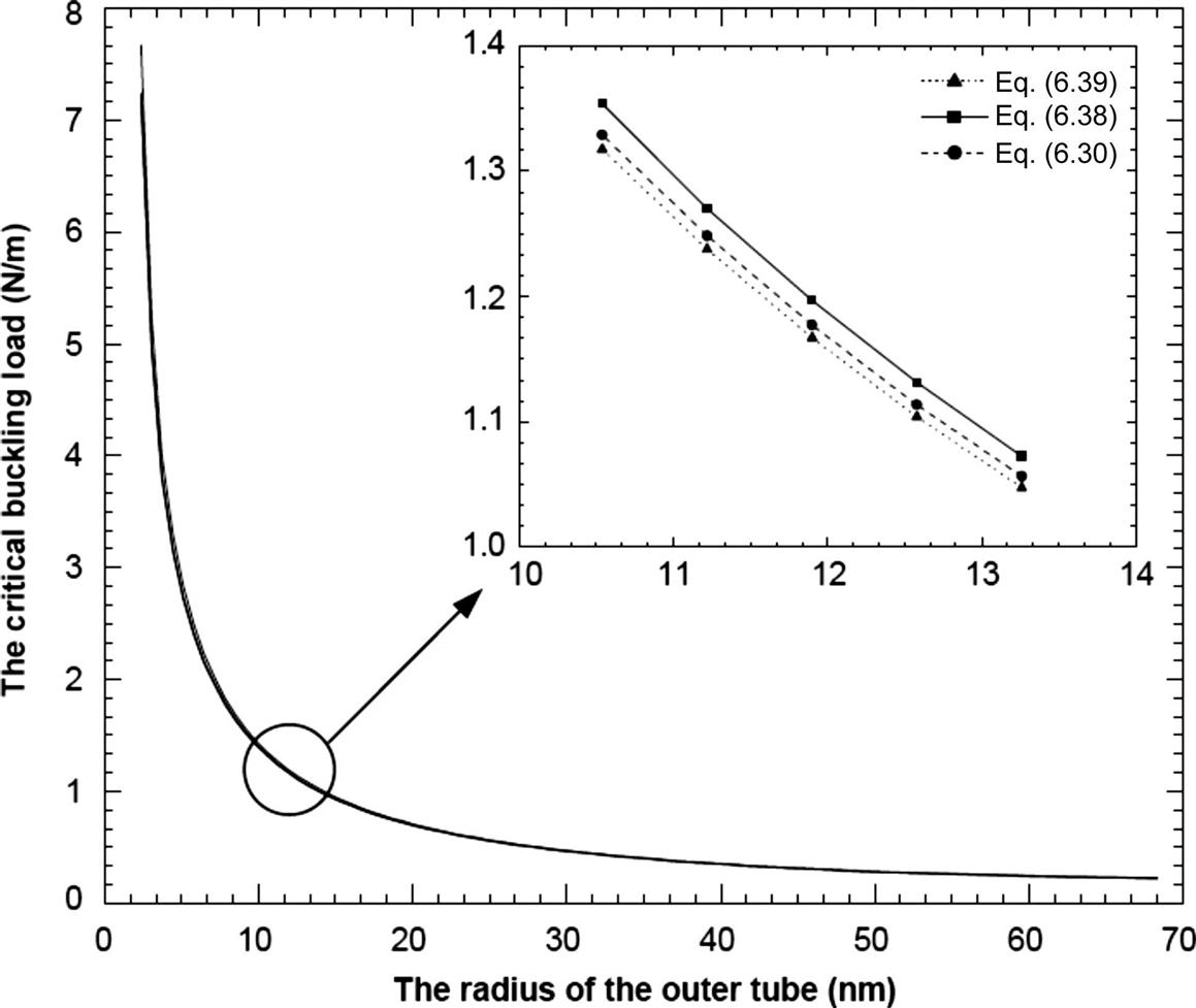
The vdW force exerted on any atom of a tube can be estimated by summing all forces between the atom and all atoms on the other tube. To simplify the calculations, we consider the nanotube as a continuum cylindrical shell and note that each carbon atom corresponds to the area of ![]() [39]. Thus, with assuming inward pressure positive, the integration of Eq. (6.3) over the entire nanotube leads to an analytical representation for the initial pressure contribution pij caused by vdW interaction
[39]. Thus, with assuming inward pressure positive, the integration of Eq. (6.3) over the entire nanotube leads to an analytical representation for the initial pressure contribution pij caused by vdW interaction
(6.4)
 (6.4)
(6.4)
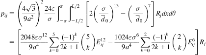
and the pressure increment due to the buckling deflection
(6.5)
 (6.5)
(6.5)
where α=1.42 Å is the C–C bond length, Rj the radius of jth layer, the subscripts i and j denote ith and jth layers, respectively, and ![]() ,
, ![]() ,
, ![]() , and
, and ![]() are the elliptic integrals defined by
are the elliptic integrals defined by
(6.6)
where m is an integer and
(6.7)
6.3 Continuum Shell Model
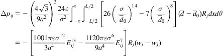
The elastic cylindrical shell theory has been adopted to study the buckling MWCNTs. An MWCNT consists of two or more single CNTs of radius Ri, thickness h, and modulus of elasticity E. The considered MWCNT is empty inside. No internal or external lateral pressures are applied to the tube except for the pressure caused by vdW interaction. We also assume that no sliding occurs between walls. Based on the classical thin-shell theory [40], the governing equations for the elastic buckling of an MWCNT can be derived as the N coupled equations, i.e.,
(6.8)
 (6.8)
(6.8)
where wi (i=1, 2, …, N) is the deflection of the ith nanotube, pi is the pressure exerted on the nanotube i due to vdW interaction between walls, and Li is the differential operator that is given by
(6.9)
in which x and θ are the axial coordinate and the circumferential coordinate, Nx=σxh and Nθ=σθh are the uniform forces per unit length in the axial and circumferential directions of the nanotube prior to buckling, σx and σθ are the axial and circumferential stresses, D is the bending stiffness of the nanotube, and
(6.10)
Note that the attractive vdW force is negative and the repulsive vdW force is positive, and the inward pressure is assumed to be positive in Eq. (6.8). Thus, with the infinitesimal buckling deflection between two layers, the net pressure due to vdW interaction can be expressed as
(6.11)
where ![]() is the initial uniform vdW pressure contribution to the ith layer from the jth layer prior to buckling, N is the total number of layers of the MWCNT, and Δpi(x, θ) is the pressure increment after buckling. As only infinitesimal buckling is considered, Δpi(x, θ) is assumed to be linearly proportional to the buckling deflection between two layers, i.e.,
is the initial uniform vdW pressure contribution to the ith layer from the jth layer prior to buckling, N is the total number of layers of the MWCNT, and Δpi(x, θ) is the pressure increment after buckling. As only infinitesimal buckling is considered, Δpi(x, θ) is assumed to be linearly proportional to the buckling deflection between two layers, i.e.,
(6.12)
where Δpij is the contribution to the pressure increment Δpi exerted on the ith layer from the jth layer, and cij is the vdW interaction coefficient.
Comparing Eqs. (6.12) and (6.5), we have
(6.13)
Eq. (6.13) furnishes the mathematical expression for the interaction coefficient that models vdW interaction after buckling in an MWCNT, where each tube has been treated as an individual continuum cylindrical shell. This more refined vdW model captures the effects of all layers, not just the effect between two adjacent layers. Moreover, the expression takes into account the size effect.
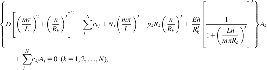
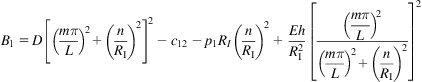
Finally, we obtain the following governing equations for the buckling of an MWCNT:
(6.14)
 (6.14)
The equations are coupled with each other due to vdW interaction.
6.4 Buckling of CNTs
The present section describes the solutions to the buckling of MWCNTs using the proposed vdW force model. We note that the buckling analysis is not sensitive to the boundary conditions [40]. Thus, throughout this section, we assume that the ends of all nanotubes are simply supported.
6.4.1 General MWCNTs
First, let us examine the buckling solutions for an MWCNT with any number of layers. The deflection of all tubes can be approximated by
(6.15)
where Ak(k=1, 2, …, N) are N unknown coefficients, L is the length of the MWCNT, m is the axial half wavenumber, and n the circumferential wavenumber. It is obvious that these approximate solutions meet the following simply supported boundary conditions exactly
(6.16)
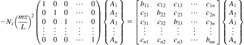
Substituting Eq. (6.15) into Eq. (6.14) yields N equations
(6.17)
 (6.17)
where pk=–Nθ/Rk and the net pressure exerted on the kth tube is assumed to be inward. Eq. (6.17) can be rewritten in the matrix form
(6.18)
 (6.18)
or, equivalently,
(6.19)
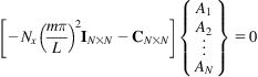 (6.19)
where
(6.20)
 (6.20)
To determine nonzero solutions of Ak, it is necessary to equate its determinant to zero. Thus, we have the characteristic equation of [C], i.e.,
(6.21)
Solving Eq. (6.21) yields the buckling load of the MWCNT relative to wavenumber of m and n.
6.4.2 An Explicit Solution for DWCNTs
As a particular case of MWCNT, a DWCNT with an inner radius RI and an outer radius RO is considered for the buckling analysis. Then, Eq. (6.17) reduces to
(6.22)
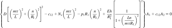 (6.22)
and
(6.23)
 (6.23)
Here the inner layer is the 1st layer and the outer layer is the 2nd layer. With the existence condition for a nonzero solution of A1 and A2, the buckling load of the DWCNTs can be obtained by solving
(6.24)
where
(6.25)
 (6.25)
and
(6.26)
 (6.26)
Because the equilibrium distance between a carbon atom and a flat monolayer is around 0.34 nm [37], any increase (![]() , i, j=1, 2) or decrease (
, i, j=1, 2) or decrease (![]() ) in space between the inner and outer tubes would cause an attractive or repulsive vdW force, respectively. Note that we assume the inward pressure to be positive. Thus, from Eq. (6.5) we have c12<0 and c21<0. In contrast,
) in space between the inner and outer tubes would cause an attractive or repulsive vdW force, respectively. Note that we assume the inward pressure to be positive. Thus, from Eq. (6.5) we have c12<0 and c21<0. In contrast,
(6.27)
Thus, the solution to Eq. (6.24) is given by
(6.28)
where the sign before the square root depends on the combination of integers n and m, as well as the constants c12 and c21.
6.4.3 The Particular Case of DWCNTs Without vdW Interaction
Considering a DWCNT without vdW interaction, we have c12=c21=p1=p2=0. Note that RO>RI, and comparing Eqs. (6.25) and (6.26), we have Bl>B2. Then, when we take the positive sign before the square root, Eq. (6.28) reduces to the classical equation for the buckling load of cylindrical shells [40]
(6.29)
 (6.29)
The axial load determined by Eq. (6.29) corresponds to the axial load exerted on the inner tube, which is modeled as an individual cylindrical shell. Similarly, when we take the negative sign before the square root, Eq. (6.28) reduces to the same classical solution as that of the buckling load of the outer tube
(6.30)
 (6.30)
The axial load determined by Eq. (6.30) is lower than that determined by Eq. (6.29). Thus, if we take the DWCNT as a whole system, the critical buckling load should be determined by minimizing the axial load solution of Eq. (6.30).
6.4.4 DWCNTs With vdW Interaction
Now, let us consider the buckling load for DWCNTs with vdW interaction. Because B1 and B2 depend on the wavenumber of m and n, the sign before the square root of Eq. (6.28) depends on the following cases.
In the case of B1B2≤c12c21
Based on the assumption that B1B2≤c12c21, one can easily arrive at
(6.31)
In addition, the vdW forces between the two tubes are equal and opposite as shown in Fig. 6.1, and the pressures exerted on the two tubes should satisfy the equilibrium condition p1RI=−p2RO. Hence, it is obvious from Eqs. (6.25) and (6.26) that B1+B2>0, and Eq. (6.31) becomes
(6.32)

To ensure that the right-hand side of Eq. (6.28) is positive, we take the positive sign before the square root in Eq. (6.28) and the solution to the axial load is given by
(6.33)
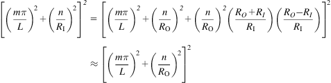
For DWCNTs with large radii, the ratio (RO–RI)/RI is very small and can be neglected. Thus, we have
(6.34)
 (6.34)
and
(6.35)
Substitution of Eqs. (6.34) and (6.35) into Eqs. (6.25) and (6.26), and then Eqs. (6.25) and (6.26) into Eq. (6.33) leads to an approximate formula for the buckling load of DWCNTs with large radii as
(6.36)
 (6.36)
Let us examine the effect of vdW interaction on the axial load. Note that, as stated above, the vdW constants are negative, i.e., c12<0 and c21<0. Thus, we can verify that the last term of the right-hand side of Eq. (6.36) is positive. Comparing Eqs. (6.30) and (6.36), it is obvious that the presence of vdW interaction will significantly increase the buckling load in the case of B1B2≤c12c21.
The case of B1B2>c12c21
Because the equilibrium distance between a carbon atom and a flat monolayer is around 0.34 nm [37], the initial pressure p1(p1<0) is very small when the interlayer separation is taken as 0.34 nm. Note that p2>0 (p2RO=−p1RI). It is clear from Eqs. (6.25) and (6.26) that we have B1>−c12 and B2>−c21 or B1B2>c12c21, which gives the following relation:
(6.37)
To obtain the lowest positive solution to Eq. (6.28), we should take the negative before the square root in Eq. (6.28) so that it becomes
(6.38)
The substitution of Eqs. (6.25) and (6.26) into Eq. (6.38) for B1 and B2 and noted Eqs. (6.34) and (6.35) yields an approximate solution for the buckling load of DWCNTs
(6.39)
 (6.39)
Our numerical results demonstrate that the prebuckling vdW forces between any two layers are attractive, as shown in Table 6.1, and the inward pressure is assumed to be positive. Hence, we have p2>0. In contrast, as stated above, the vdW constant c12<0 and c21<0. In addition, we have ![]() because the surface area of the outer tube is larger than that of the inner tube, which means that the sum of vdW forces from all atoms on the surface of the outer tube is larger than that of the inner tube. Thus, it is verified that the second term in the square root is positive and then the last term on the right-hand side of Eq. (6.39) is negative. Hence, comparing Eq. (6.30) with Eq. (6.39) indicates that Eq. (6.39) will result in a lower buckling load than that obtained without vdW interaction. However, as stated before, when the outer (inner) tube deflects outward (inward), the vdW force caused would be attractive, whereas when the outer (inner) tube deflects inward (outward), the vdW force would be repulsive. Hence, vdW interaction always has an effect against buckling. This verifies that vdW interaction will raise the buckling load. It should be noted that Eq. (6.39) is only an approximate expression for the buckling load of a DWCNT, and cannot accurately describe the influence of vdW interaction on buckling behavior. In our numerical examples, the exact solution given by Eq. (6.38) shows that vdW force results in a higher buckling load than is obtained without vdW force, while the approximate Eq. (6.39) leads to a lower buckling load. This difference is caused by ignorance of the terms related to the ratio of (RO−RI)/RI in Eq. (6.39). If we take c12=c21, then Eq. (6.39) reduces to the Ru’s result [16].
because the surface area of the outer tube is larger than that of the inner tube, which means that the sum of vdW forces from all atoms on the surface of the outer tube is larger than that of the inner tube. Thus, it is verified that the second term in the square root is positive and then the last term on the right-hand side of Eq. (6.39) is negative. Hence, comparing Eq. (6.30) with Eq. (6.39) indicates that Eq. (6.39) will result in a lower buckling load than that obtained without vdW interaction. However, as stated before, when the outer (inner) tube deflects outward (inward), the vdW force caused would be attractive, whereas when the outer (inner) tube deflects inward (outward), the vdW force would be repulsive. Hence, vdW interaction always has an effect against buckling. This verifies that vdW interaction will raise the buckling load. It should be noted that Eq. (6.39) is only an approximate expression for the buckling load of a DWCNT, and cannot accurately describe the influence of vdW interaction on buckling behavior. In our numerical examples, the exact solution given by Eq. (6.38) shows that vdW force results in a higher buckling load than is obtained without vdW force, while the approximate Eq. (6.39) leads to a lower buckling load. This difference is caused by ignorance of the terms related to the ratio of (RO−RI)/RI in Eq. (6.39). If we take c12=c21, then Eq. (6.39) reduces to the Ru’s result [16].
Table 6.1
Prebuckling Pressure pij (MPa) Due to vdW Interaction for a Nine-walled CNT With Various Innermost Radii RI [22]
| RI (nm) | p51 | p52 | p53 | p54 | p56 | p57 | p58 | p59 |
| 0.34 | −3.4978 | −19.537 | −173.80 | −522.01 | −635.30 | −263.53 | −37.790 | −9.5832 |
| 0.68 | −3.4978 | −21.417 | −182.31 | −529.42 | −624.19 | −256.82 | −36.488 | −9.1808 |
| 1.36 | −5.0877 | −23.619 | −192.61 | −539.37 | −610.69 | −248.29 | −34.830 | −8.6677 |
| 2.04 | −5.5085 | −24.881 | −198.63 | −545.66 | −602.81 | −243.10 | −33.816 | −8.3533 |
| 2.72 | −5.7785 | −25.702 | −202.58 | −549.98 | −597.64 | −239.60 | −33.132 | −8.1406 |
| 3.40 | −5.9667 | −26.277 | −205.37 | −553.12 | −593.99 | −237.08 | −32.638 | −7.9868 |
| 4.08 | −6.1054 | −26.704 | −207.45 | −555.50 | −591.27 | −235.18 | −32.264 | −7.8704 |
| 4.76 | −6.2120 | −27.032 | −209.05 | −557.37 | −589.17 | −233.70 | −31.972 | −7.7792 |
| 5.44 | −6.2963 | −27.293 | −210.33 | −558.88 | −587.51 | −232.51 | −31.737 | −7.7058 |
| 6.12 | −6.3648 | −27.505 | −211.37 | −560.12 | −586.15 | −231.53 | −31.544 | −7.6455 |
| 6.80 | −6.4215 | −27.681 | −212.23 | −561.16 | −585.02 | −230.71 | −31.383 | −7.5949 |
| 9.52 | −6.5758 | −28.162 | −214.60 | −564.04 | −581.93 | −228.46 | −30.936 | −7.4551 |
| 16.32 | −6.7507 | −28.709 | −217.31 | −567.39 | −578.41 | −225.84 | −30.416 | −7.2913 |
| 26.52 | −6.8517 | −29.026 | −218.89 | −569.38 | −576.36 | −224.29 | −30.108 | −7.1945 |
| 42.84 | −6.9159 | −29.228 | −219.89 | −570.66 | −575.06 | −223.30 | −29.910 | −7.1320 |
| 68.00 | −6.9554 | −29.353 | −220.51 | −571.45 | −574.26 | −222.69 | −29.787 | −7.0931 |
| 95.20 | −6.9749 | −29.414 | −220.82 | −571.82 | −573.84 | −222.38 | −29.726 | −7.0738 |
| 122.40 | −6.9858 | −29.448 | −220.99 | −573.04 | −574.62 | −222.21 | −29.692 | −7.0630 |
| 152.32 | −6.9934 | −29.472 | −221.11 | −570.26 | −571.44 | −222.09 | −29.669 | −7.0555 |

We first examine vdW interaction for MWCNTs with various innermost radii and make a comparison with Wang et al.’s result [20]. The buckling loads for DWCNTs are also calculated and compared with the results of Ru [16]. Having validated the derived formula, the buckling loads are investigated for various MWCNTs. The effect of vdW interaction on the buckling load is also highlighted. Now let us consider an MWCNT with an innermost radius RI and an outermost radius RO as shown in Fig. 6.1. Suppose that each tube has the same length L and thickness h, and is modeled as an individual cylindrical shell. The MWCNT is subjected to the combined action of axial compression and vdW interaction. No internal or external lateral pressures are considered for the buckling analysis of the MWCNT. Following most published papers on CNTs, the initial interlayer separation between the two adjacent layers is assumed to be 0.34 nm. The parameters used in the vdW potential (given by Eq. (6.1)) are taken as ε=2.968 meV and σ=3.407 Å [41].
6.4.5 vdW Interaction Before Buckling
To illustrate vdW interaction prior to buckling, the prebuckling vdW pressures between two adjacent layers are calculated using the derived Eq. (6.4) for a nine-walled CNT with innermost radius range of 0.34–152.32 nm and are presented in Table 6.1. The value of pij in Table 6.1 represents the pressure contribution to layer i from layer j due to vdW interaction before buckling. Note that the negative sign in Table 6.1 represents an attraction between two layers. It can be seen that the greatest influence of vdW interaction before buckling occurs between two adjacent layers, and the pressure decreases monotonically with increasing distance between two layers until it is very small, or is negligible when the distance is large enough. The curvature effect on the vdW pressure is also reflected in Table 6.1. With a small tube radius (or large curvature), the prebuckling vdW pressure varies quickly and the curvature effect becomes significant. However, with a large radius (or small curvature), the pressure varies only slightly, and the curvature effect can be neglected. The prebuckling pressures due to vdW interaction approach constant values as the radius increases. These constants are around −570 MPa for p54 and p56, −221 MPa for p53 and p57, −29 MPa for p52 and p58, and −7 MPa for p51 and p59.
To show the dependence of all vdW pressures between two adjacent layers of a nine-walled CNT on the radii of tubes, the prebuckling pressure contributions to the 1st and 9th layers from one side layer, the 2nd, 3rd, 4th, 5th, 6th, 7th, and 8th layers from two side layers are presented in Fig. 6.2 for various innermost radii of the nine-walled CNT. The innermost layer is the 1st layer and the outermost layer is the 9th layer. For any two adjacent layers, the pressure contribution to the outer tube from inner tube is plotted in the curve with solid symbol, as shown in Fig. 6.2. The largest absolute value of the pressure contribution (p98) occurs on the outermost tube for any innermost radius of the nine-walled CNT, and then the pressure contribution decreases from the outermost tube to the innermost tube until the pressure contribution to the tube next to the innermost tube is smallest (p21). For the pressure contribution to the inner tube from outer tube (the curves with empty symbols in Fig. 6.2), the largest pressure contribution (p12) occurs on the innermost tube and the smallest contribution (p89) occurs on the tube next to the outermost tube. For the small radius, the pressure contribution to the outer tube from inner tube between any two adjacent layers drops sharply, whereas the pressure contribution to the inner tube from the outer tube rises sharply with the increase of radius, which means that the size of the radius significantly affects the prebuckling vdW pressure when the radius is small. As the radius increases, the pressures decrease (or increase) slowly and stably until the pressures between all of the adjacent layers approach a constant of around −570 MPa.

6.4.6 vdW Interaction After Buckling
To illustrate the derived Eq. (6.13), the vdW interaction coefficients cij are calculated and presented in Table 6.2 for a nine-walled CNT with an innermost radii range of 0.34–152.32 nm. The values of the coefficients cij in Table 6.2 represent the pressure increment contribution (due to vdW interaction after buckling) to layer i from layer j. It can be seen that vdW interaction between two adjacent layers (c54 and c56) is much larger than that between two nonadjacent layers (such as c53 and c59), and the coefficient decreases rapidly from the adjacent layer to the innermost or outermost layer. Thus, when the distance between the two layers is large enough, the value of the coefficient is very small and vdW interaction can be neglected. It should be noted that the negative sign in Table 6.2 represents an attraction between two layers, whereas the positive sign represents repulsion. The coefficients between two adjacent layers are compared with the results obtained by Wang et al. [20] for various innermost radii, as shown in Table 6.2. It can be seen that the present results (based on the newly proposed vdW interaction model) are about 10% higher than Wang’s results. However, the value of the percentage differences in the coefficient values depends on the radius of the tube. Note that Wang assumed the interaction coefficient c to be curvature independent, and only vdW interaction between two adjacent layers was taken into consideration. However, as shown in Table 6.2, the coefficients cij are curvature dependent. This is because the surface area of the tube varies with respect to the radius, and the force exerted on each carbon atom of the surface of tube i is the sum of vdW forces from all atoms on the surface of tube j. Thus, the coefficients cij vary with the different radii of tubes. It is interesting to note that with the increase of the radius, when j<i, the absolute values of coefficient cij increase, whereas when j>i, the absolute values of coefficient cij decrease. However, when the radius is large enough, the coefficient cij is curvature independent [42,43] and approaches a constant. For example, as shown in Table 6.2, the coefficients almost approach the same constant values of −108 GPa/nm for c54 and c56, 1.87 GPa/nm for c53 and c57, 0.169 GPa/nm for c52 and c58, and 0.03 GPa/nm for c5l and c59.
Table 6.2
vdW Interaction Coefficients Cij (GPa/nm) for a Nine-Walled CNT With Various Innermost Radii RI [22]
| RI (nm) | c51 | c52 | c53 | c54 | c56 | c57 | c58 | c59 |
| 0.34 | 0.0149 | 0.1105 | 1.463 | 97.14 | 118.98 | 2.2234 | 0.2152 | 0.0409 |
| −99.19a | ||||||||
| 0.68 | 0.0183 | 0.1216 | 1.5371 | 99.15 | 117.33 | 2.1676 | 0.2080 | 0.0392 |
| −99.19a | ||||||||
| 1.36 | 0.0217 | 0.1345 | 1.6257 | 101.62 | 115.23 | 2.0964 | 0.1987 | 0.0371 |
| −99.19a | ||||||||
| 2.04 | 0.0235 | 0.1419 | 1.6771 | 103.07 | 113.94 | 2.0529 | 0.1930 | 0.0358 |
| −99.19a | ||||||||
| 2.72 | 0.0247 | 0.1467 | 1.7108 | 104.02 | 113.08 | 2.0236 | 0.1891 | 0.0349 |
| −99.19a | ||||||||
| 3.40 | 0.0256 | 0.1500 | 1.7345 | 104.69 | 112.46 | 2.0025 | 0.1863 | 0.0342 |
| −99.19a | ||||||||
| 4.08 | 0.0262 | 0.1524 | 1.7522 | 105.19 | 111.99 | 1.9865 | 0.1842 | 0.0337 |
| −99.19a | ||||||||
| 4.76 | 0.0266 | 0.1543 | 1.7658 | 105.59 | 111.63 | 1.9740 | 0.1826 | 0.0333 |
| −99.19a | ||||||||
| 5.44 | 0.0270 | 0.1558 | 1.7766 | 105.90 | 111.33 | 1.9640 | 0.1812 | 0.0330 |
| −99.19a | ||||||||
| 6.12 | 0.0273 | 0.1571 | 1.7855 | 106.15 | 111.09 | 1.9558 | 0.1801 | 0.0328 |
| −99.19a | ||||||||
| 6.80 | 0.0275 | 0.1581 | 1.7928 | 106.36 | 110.89 | 1.9489 | 0.1792 | 0.0326 |
| −99.19a | ||||||||
| 9.52 | 0.0282 | 0.1608 | 1.8129 | 106.94 | 110.33 | 1.9299 | 0.1767 | 0.0320 |
| −99.19a | ||||||||
| 16.32 | 0.0289 | 0.1640 | 1.8358 | 107.60 | 109.69 | 1.9078 | 0.1737 | 0.0313 |
| −99.19a | ||||||||
| 26.52 | 0.0294 | 0.1658 | 1.8491 | 107.99 | 109.31 | 1.8948 | 0.1720 | 0.0309 |
| −99.19a | ||||||||
| 42.84 | 0.0297 | 0.1669 | 1.8576 | 108.23 | 109.07 | 1.8864 | 0.1708 | 0.0306 |
| −99.19a | ||||||||
| 68.00 | 0.0298 | 0.1676 | 1.8629 | 108.28 | 108.91 | 1.8812 | 0.1701 | 0.0304 |
| −99.19a | ||||||||
| 95.20 | 0.0299 | 0.1680 | 1.8655 | 108.32 | 108.84 | 1.8786 | 0.1698 | 0.0303 |
| −99.19a | ||||||||
| 122.40 | 0.0300 | 0.1682 | 1.8669 | 108.35 | 108.80 | 1.8772 | 0.1696 | 0.0303 |
| −99.19a | ||||||||
| 152.32 | 0.0300 | 0.1683 | 1.8679 | 108.40 | 108.75 | 1.8762 | 0.1694 | 0.0303 |
| −99.19a |
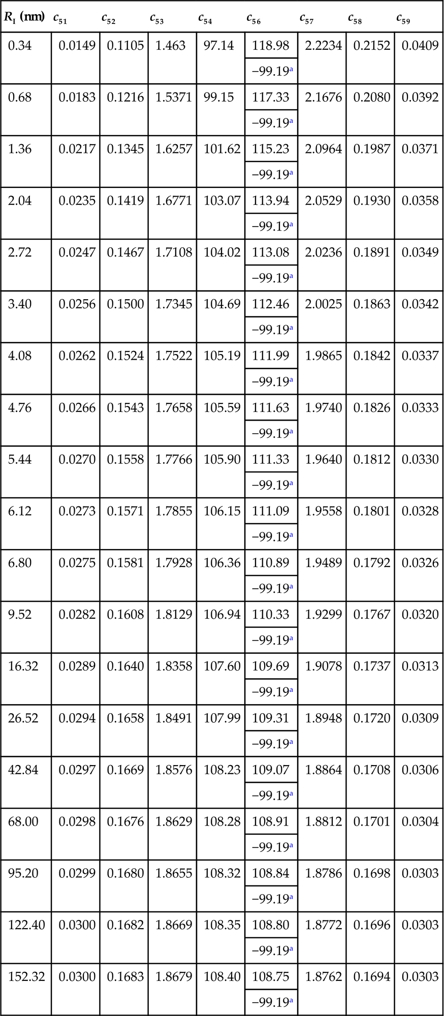
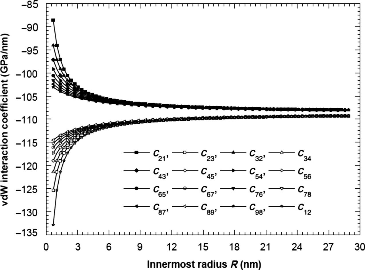
The relationships of the coefficients and the innermost radius of the nine-walled CNT are plotted in Fig. 6.3. Similar to the prebuckling pressure, the coefficients corresponding to the pressure increment contribution to outer (or inner) tube from inner (or outer) tube between any two adjacent layers drop (rise) sharply with the increase of radius when the radius of the tube is small. This implies that the vdW interaction coefficients are highly dependent on the size of the radius for MWCNTs with small radii. Large radii have little influence on the coefficients, as shown in Fig. 6.3. Similarly, the coefficients approach the same constant of −108 GPa/nm, which is about 10% higher than the Wang et al. result [20].
6.4.7 Buckling of a DWCNT
The buckling behavior of MWCNTs is investigated using the vdW interaction model we have developed. Comparison between the present model and Ru’s model is carried out for the buckling of DWCNTs. For all the considered MWCNTs, the bending stiffness D=0.85 eV, Eh=360 J/m2 [3], and the length to the outermost radius ratio L/RO=10.
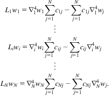
To examine the validity of the approximate formula (Eq. 6.39), we simulated the buckling loads with the circumferential wavenumber n=6 for a DWCNT with inner-tube radius RI=11.9 nm, and compared them with results calculated using the proposed exact solution (Eq. 6.38), the classical shell model (Eq. 6.30) and Ru’s model [16], as shown in Fig. 6.4. The relative errors for the lowest buckling loads from Eqs. (6.38) and (6.39), and from Eq. (6.39) and the Ru’model [16] are 2.46% and 0.49% respectively. It can be seen from Fig. 6.4 that the buckling loads obtained from Eq. (6.30) (without vdW interaction) are larger than those from Eq. (6.39) and Ru’s model (taking vdW interaction into account), but smaller than those from Eq. (6.38) (taking vdW interaction into consideration). As mentioned earlier, vdW interaction always has an effect against buckling deflection. Thus, the presence of vdW interaction will lead to a higher buckling load. With the vdW forces taken into account, the numerical simulation from Eq. (6.38) illustrates that the buckling load is indeed bigger than when the vdW forces are not considered. As for the lower buckling loads from Eq. (6.39), as shown in Fig. 6.4, they occur because the ignorance of the terms related to the ratio of (RO−RI)/RI in Eq. (6.39) leads to the results smaller than those in Eq. (6.30). The buckling loads in Ru’s model [16] are also smaller than those in the classical shell model without vdW forces. Ru reported that the vdW forces do not increase the critical axial strain for infinitesimal buckling of DWCNTs. It is clear that the influence of the terms related to the ratio of (RO−RI)/RI on the buckling load is not considered in his paper.

Fig. 6.5 shows the curvature effects on the critical buckling loads of DWCNTs. The critical buckling loads are obtained by minimizing the results from Eqs. (6.38) and (6.39) with respect to the wavenumbers n and m. It can be seen that the critical buckling load is a function of the tube radius. With a very small radius, say less than 5 nm, the critical load drops rapidly, indicating that the curvature effect plays an important role in the critical buckling load for a small radius. For DWCNTs with a large radius, say bigger than 40 nm, the critical load varies very slowly, showing that the dependence of the critical load on the radius can be neglected. The relative errors between the critical buckling loads obtained by Eqs. (6.38) and (6.39) are examined and shown in Fig. 6.6. As can be seen, the relative error is significant with very small radii. However, when the radius is big, say bigger than 40 nm, the relative error is very small and is negligible.