
Nonlocal Elasticity Theories
Abstract
Despite the efficiency of classical continuum models with relatively simple formulae in carbon nanotube (CNT) mechanical analysis, their applicability to the identification of the small-scale effect on the mechanical behavior of CNTs is questionable. This limited applicability of the classical or local continuum models at small length scales is partly due to the fact that classical modeling does not admit intrinsic size dependence in the elastic solutions of inclusions and inhomogeneities. The nonlocal elasticity theory assumes that the stress state at a given reference point is a function of the strain field at every point in the body. Therefore, the scale effect can be considered in constitutive equations simply as a material parameter. This chapter aims to investigate the applicability of nonlocal beam, nonlocal rod models, and nonlocal shell models for free transverse, longitudinal, and torsional vibrations and waves in single-walled and double-walled CNTs through verifications from molecular dynamics (MD) simulations. Beam models and MD simulations are employed to study the transverse vibration of single-walled CNTs (SWCNTs). The nonlocal rod model is used to predict the MD results for longitudinal and torsional vibrations of SWCNTs. The nonlocal shell model is applied to study transverse and torsional wave in single-walled and double-walled CNTs.
Keywords
Nonlocal beam; nonlocal rod; nonlocal shell; free transverse vibration; free longitudinal vibration; free torsional vibration
7.1 Introduction
Carbon nanotubes (CNTs) have attracted worldwide attention [1–4] for their wide range of applications, including atomic-force microscopes, field emitters, frictionless nanoactuators, nanomotors, nanobearings, nanosprings, nanofillers for composite materials, and nanoscale electronic devices [4]. In addition to experimental endeavors, CNT modeling is classified into two main categories. The first is atomic modeling, which includes such techniques as molecular dynamics (MD) and TBMD and the density functional model [5–11]. Li and Chou [12] reported an atomistic simulation of single-walled CNT (SWCNT) subjected to harmonic waves. Atomic modeling is limited to systems with a small number of molecules and atoms and is therefore confined to small-scale modeling. The second category is continuum modeling [13–18], which includes classical (or local) beam and shell theories that are practical for analyzing CNTs for large-scale systems. Successful work has been conducted with continuum modeling, such as buckling analysis, dynamics studies, and mechanical property investigations of CNTs [12,19–39]. Dynamic mechanical behaviors of CNTs have been studied widely in recent years. Elastic wave propagation in CNTs was studied through continuum models and MD simulations [40–44]. Vibrations of CNTs are of importance in various applications, such as sensors, high frequency oscillators, and other nanoscale devices. Vibrations of CNTs have been investigated by continuum models and molecular mechanics methods [45–49]. It is important to apply accurate theoretical models for the natural frequencies and mode shapes of CNTs [50]. The modeling and simulation methods of vibrating CNTs were reviewed by Gibson et al. [50]. Static and dynamic mechanical deflections can be electrically induced in cantilevered, multi-walled CNTs (MWCNTs) in a transmission electron microscope [51]. Natsuki et al. [52] investigated the wave propagation in SWCNTs and double-walled CNTs (DWCNTs) conveying fluid through the use of the shell model. Insepov et al. [53] summarized a few ways to activate surface-traveling waves on the nanotube surface.
Although the classical continuum models are efficient in CNT mechanical analysis through their relatively simple formulae, their applicability to the identification of the small-scale effect on the mechanical behavior of CNTs is questionable. This limited applicability of the classical or local continuum models at small-length scales is partly due to the fact that classical modeling does not admit intrinsic size dependence in the elastic solutions of inclusions and inhomogeneities. Sun and Zhang [54] discussed the limited applicability of continuum models to nanotechnology and proposed a semicontinuum model to analyze nanomaterials. The values of the material properties were found to be completely dependent on the thickness of the plate structure. The modeling of such a size-dependent phenomenon has become an active and interesting subject of research in continuum modeling [8,55]. Wang [56] demonstrated the effective in-plane stiffness and bending rigidity of armchair and zigzag CNTs through analysis of the representative volume element of a graphene layer with continuous elastic models. It was found that the bending rigidity of the CNTs had a size effect. Wang and Hu [57] studied flexural wave propagation in SWCNTs through the use of a nonlocal elastic Timoshenko beam model and an MD simulation based on the first-generation reactive empirical bond order (REBO) potential [58]. Liew et al. [59] studied the flexural wave propagation in SWCNTs through the use of an MD simulation based on the second-generation REBO [60]. The material microstructure at small size, such as the lattice spacing between individual atoms, becomes increasingly important and the discrete structure of the material can no longer be homogenized into a continuum. Therefore, the nonlocal elastic continuum model is expected to take into account the scale effect when tackling large-scale nanomaterial analysis. Size effects often become prominent at nanometer scales, and there is increasing interest in the general area of nanotechnology in explicitly addressing the cause of these effects [61].
The nonlocal elasticity theory [62,63] assumes that the stress state at a given reference point is a function of the strain field at every point in the body. Therefore, the scale effect can be considered in constitutive equations simply as a material parameter. However, the classical elasticity theory cannot account for the scale effect, as the stress state is uniquely dependent on the strain state at the same point. Peddieson et al. [64] expected the application of the nonlocal elasticity theory to have potential in the analysis of nanomaterials. They applied it to the formulation of a nonlocal version of the Euler–Bernoulli beam model and concluded that nonlocal continuum mechanics could potentially play a useful role in nanotechnology applications. Further applications of nonlocal continuum mechanics have been employed in the study of CNT buckling. Sudak [65] presented a multiple column model for the linearized column buckling of MWCNTs using the theory of nonlocal continuum mechanics. Zhang et al. [66] proposed a nonlocal multishell model for the axial buckling of MWCNTs under axial compression. The nonlocal elastic Euler–Bernoulli and Timoshenko beam models were applied to study wave propagation in CNTs [67]. Wang and Varadan [44] studied wave propagation in CNTs based on the nonlocal elastic shell theory. Both theoretical analyses and numerical simulations have explicitly revealed the small-scale effect on wave dispersion relations for different CNT wavenumbers in the longitudinal and circumferential directions and for different wavelengths in the circumferential direction. However, no MD simulations have been available for the validation of shell models and beam models considering the vdW interaction between adjacent tubes in studying transverse, torsional wave, and flexural propagation in CNTs.
This chapter aims to investigate the applicability of nonlocal beam models, nonlocal rod models, and nonlocal shell models for free transverse, longitudinal, and torsional vibrations and waves in SWCNTs and DWCNTs through verifications from MD simulations. Beam models and MD simulations are employed to study the transverse vibration of SWCNTs. The nonlocal rod model is used to predict the MD results for longitudinal and torsional vibrations of SWCNTs. The nonlocal shell model is applied to study transverse and torsional wave in SWCNTs and DWCNTs. The free transverse, longitudinal, and torsional vibrations of SWCNTs with two different boundary conditions are studied.
7.2 Nonlocal Elastic Beam Model
7.2.1 Nonlocal Beam and Rod Models for Vibration of SWCNTs
The Euler–Bernoulli beam model is usually employed in the analysis of longer one-dimensional beamlike structures, normally with ratio of the length to the thickness over 20 in engineering structures. If the cross-sectional dimensions are not small enough compared to the length of the beam, we need to consider the effects of rotary inertia and shear deformation using Timoshenko beam model [68]. To account for small-scale effects on CNT’s mechanical behaviors, the nonlocal beam and shell models have been employed to overcome the limitation of the applicability of the classical or local continuum modes at small length scales [35,40,41,47,65,69].
The natural frequencies of the local Euler–Bernoulli beam are shown as [68]
(7.1)
where ![]() =1.875 and 4.73 are for the fundamental frequency of a cantilevered beam and a clamped–clamped beam, respectively. l is the length of the beam.
=1.875 and 4.73 are for the fundamental frequency of a cantilevered beam and a clamped–clamped beam, respectively. l is the length of the beam.
The governing equation for free vibration of the nonlocal Euler–Bernoulli beam [67] is proposed to be:
(7.2)
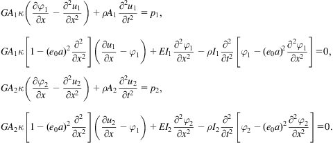
The nonlocal Timoshenko model needs to be employed to account for the small scale effect and the effects of rotary inertia and shear deformation. The governing equations for the vibrations of nonlocal Timoshenko beam are as follows [47]:
(7.3)
 (7.3)
(7.3)
where ![]() is the beam cross-sectional area.
is the beam cross-sectional area. ![]() = 2.27 g/cm3 is the density of CNT.
= 2.27 g/cm3 is the density of CNT. ![]() is Timoshenko’s shear coefficient which depends on the shape of the cross-section.
is Timoshenko’s shear coefficient which depends on the shape of the cross-section. ![]() =0.5 is used for SWCNT [57]. G=E/(2(1+
=0.5 is used for SWCNT [57]. G=E/(2(1+![]() )) is the shear modulus.
)) is the shear modulus. ![]() is the area moment of inertia, where
is the area moment of inertia, where ![]() and
and ![]() are the outside diameter and inside diameter of SWCNTs, respectively. The wall thickness of an SWCNT is 0.34 nm. The length of the C–C bond is a=0.142 nm. The parameter
are the outside diameter and inside diameter of SWCNTs, respectively. The wall thickness of an SWCNT is 0.34 nm. The length of the C–C bond is a=0.142 nm. The parameter ![]() is the scale coefficient revealing the small scale effect on the responses of structures of nanosize.
is the scale coefficient revealing the small scale effect on the responses of structures of nanosize.
Eringen [63] proposed ![]() as 0.39 by matching the dispersion curves from the nonlocal theory for a plane waves with the Born–Karman model of lattice dynamics. However, there are no experiments conducted to determine the value of
as 0.39 by matching the dispersion curves from the nonlocal theory for a plane waves with the Born–Karman model of lattice dynamics. However, there are no experiments conducted to determine the value of ![]() for CNTs. Wang and Hu proposed
for CNTs. Wang and Hu proposed ![]() used in the nonlocal beam model [57]. Zhang et al. [35] estimated
used in the nonlocal beam model [57]. Zhang et al. [35] estimated ![]() by matching the theoretical buckling strain obtained by the nonlocal thin shell model [66] to those from molecular mechanics simulations given by Sears and Batra [70]. A conservative estimate of the scale coefficient
by matching the theoretical buckling strain obtained by the nonlocal thin shell model [66] to those from molecular mechanics simulations given by Sears and Batra [70]. A conservative estimate of the scale coefficient ![]() <2.0 nm for an SWCNT if the measured wave propagation frequency value for the SWCNT is greater than 10 THz [67]. Hu et al. [41] estimated the values of
<2.0 nm for an SWCNT if the measured wave propagation frequency value for the SWCNT is greater than 10 THz [67]. Hu et al. [41] estimated the values of ![]() =0.6 and 0.2 for the transverse and torsional wave propagation in CNTs, respectively, by matching the dispersions of CNTs observed from the MD results with the numerical results obtained from the nonlocal shell model. In this study, we will fix a=0.142 nm which is the length of C–C bond and provide an estimation of parameter
=0.6 and 0.2 for the transverse and torsional wave propagation in CNTs, respectively, by matching the dispersions of CNTs observed from the MD results with the numerical results obtained from the nonlocal shell model. In this study, we will fix a=0.142 nm which is the length of C–C bond and provide an estimation of parameter ![]() by matching the fundamental frequency of SWCNTs observed from MD simulations with the numerical results obtained from the nonlocal beam and rod models. The parameter
by matching the fundamental frequency of SWCNTs observed from MD simulations with the numerical results obtained from the nonlocal beam and rod models. The parameter![]() is postulated to be dependent on the diameter and boundary conditions, and independent on the length of SWCNT in this study.
is postulated to be dependent on the diameter and boundary conditions, and independent on the length of SWCNT in this study.
The bending moment and shear force of a nonlocal Timoshenko beam are as follows [47]:
(7.4)
(7.5)
The boundary conditions for a cantilevered nonlocal Timoshenko beam:
(7.6)
The boundary conditions for a clamped–clamped nonlocal Timoshenko beam:
(7.7)
The free vibration solution for CNTs can be expressed as:
(7.8)
where ![]() . The natural frequencies and mode shapes of nonlocal Timoshenko beam can be calculated by the finite difference method.
. The natural frequencies and mode shapes of nonlocal Timoshenko beam can be calculated by the finite difference method.
Next, we will introduce nonlocal rod theory for the analysis of longitudinal and torsional vibrations of SWCNT. The nonlocal constitutive relation is as follows [63]:
(7.9)
Based on Eq. (7.9), the governing equation for the longitudinal vibration of the nonlocal rod is given by
(7.10)
Substituting u=U(x)eiwt into (7.10) and using the boundary conditions, we can find the natural frequency of longitudinal and torsional vibrations of cantilevered and clamped–clamped nonlocal rods.
The natural frequency of longitudinal vibration of a cantilevered nonlocal rod is derived as
(7.11)
The natural frequency of longitudinal vibration of a clamped–clamped nonlocal rod is derived as
(7.12)
For torsional vibration of nonlocal rod, the Young’s modulus E in the above formulas of natural frequencies should be replaced by shear modulus G. Poisson’s ratio ![]() and Young’s modulus E calculated from the MD simulations for the test of axial tension are listed in Table 7.1.
and Young’s modulus E calculated from the MD simulations for the test of axial tension are listed in Table 7.1.
Table 7.1
Young’s Modulus and Poisson’s Ratio of SWCNT [40]
| SWCNT | Young’s Modulus (TPa) | Poisson’s Ratio |
| (5, 5) | E=0.89 | |
| (10, 10),(15, 15) | E=0.83 | |
| (10, 0) | E=0.96 | |
| (19, 0) | E=0.81 | |
| (20, 20) | E=0.84 |

MD simulations for SWCNTs are conducted to verify the applicability of the nonlocal beam and nonlocal rod models for free transverse, longitudinal, and torsional vibrations of SWCNTs [71]. The interaction of atoms is described by the second-generation REBO potential energy expression for hydrocarbons [60] and there is no temperature control in the MD simulations. The verlet algorithm in the velocity form with time step 1 fs is used to simulate the vibration of SWCNTs. The shortest and longest SWCNTs including (5, 5), (10, 10), (15, 15), and (20, 20) SWCNTs in the MD simulations are 1.2 and 9.0 nm, respectively.
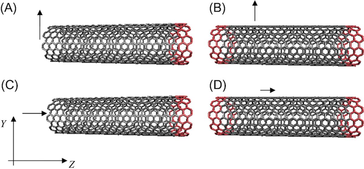
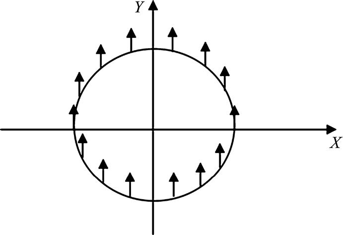
The atoms at the end of SWCNT and the middle of SWCNT are moved away from their equilibrium positions in the Y direction as shown in Fig. 7.1A and B, respectively. Fig. 7.1C and D shows that the atoms will be moved in the Z direction to produce the longitudinal vibration of SWCNT. The torsional vibration of SWCNT can be realized through releasing the torsional SWCNT in MD simulation. For example, when SWCNT are stretched from its equilibrium position in the Y direction, the tension acts as the restoring force that brings the SWCNT to its original undeformed position. The deformed SWCNT with different boundary conditions can vibrate transversely at its natural frequency. The displacement d of a cross-section of the SWCNT is calculated as follows: ![]() , where n is the number of atoms at the cross-section of SWCNT.
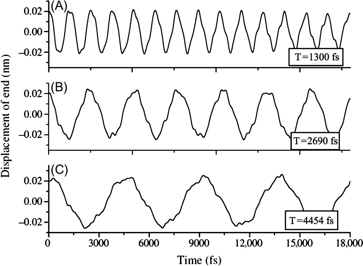
, where n is the number of atoms at the cross-section of SWCNT. ![]() is the displacement of the i atom. Each atom at the cross-section passes through its respective equilibrium position simultaneously which is observed from the MD simulations. Fig. 7.2 shows that the fundamental vibration mode can be excited after a small deflection of cantilevered SWCNT is produced. The transverse deflections of SWCNT during the vibration at different time are presented. The vibrations of the end of the cantilevered (10, 10) SWCNT with different lengths are shown in Fig. 7.3. The periods and fundamental frequencies can be calculated from the MD simulations.
is the displacement of the i atom. Each atom at the cross-section passes through its respective equilibrium position simultaneously which is observed from the MD simulations. Fig. 7.2 shows that the fundamental vibration mode can be excited after a small deflection of cantilevered SWCNT is produced. The transverse deflections of SWCNT during the vibration at different time are presented. The vibrations of the end of the cantilevered (10, 10) SWCNT with different lengths are shown in Fig. 7.3. The periods and fundamental frequencies can be calculated from the MD simulations.

7.2.2 Nonlocal Elastic Beam Models for Flexural Wave Propagation in DWCNTs
In nonlocal elasticity [62], the stress at a reference point x is considered to be a function of the strain field at every point in the body. The basic equations for linear, homogeneous, isotropic, nonlocal elastic solid with zero body force are given as [63]
(7.13)
 (7.13)
where ![]() and
and ![]() are stress and strain tensors, respectively,
are stress and strain tensors, respectively, ![]() is the elastic modulus tensor in classical isotropic elasticity,
is the elastic modulus tensor in classical isotropic elasticity, ![]() is the displacement vector,
is the displacement vector, ![]() is the nonlocal modulus or attenuation function which incorporates the nonlocal effects at the reference point x produced by local strain at the source
is the nonlocal modulus or attenuation function which incorporates the nonlocal effects at the reference point x produced by local strain at the source ![]() into the constitutive equations, and
into the constitutive equations, and ![]() is the Euclidean distance. In
is the Euclidean distance. In![]() e0 is a constant appropriate to each material, a is an internal characteristic length (e.g., length of C–C bond, lattice parameter, and granular distance), and l is an external characteristic length (e.g., crack length and wavelength).
e0 is a constant appropriate to each material, a is an internal characteristic length (e.g., length of C–C bond, lattice parameter, and granular distance), and l is an external characteristic length (e.g., crack length and wavelength).
Integral-partial differential equations of the above linear nonlocal elasticity are reduced to singular partial differential equations of a special class of physically admissible kernel [63]. Hence, Hooke’s law for stress and strain relation in the polar coordinate system is thus expressed by
(7.14)
where ![]() is the axial stress and
is the axial stress and ![]() is the axial strain. The parameter e0a is the scale coefficient revealing the small-scale effect on the responses of structures of nanosize. The parameter e0=0.39 was given by Eringen [63], but there are no experiments conducted to determine the value of e0 for CNT. Wang and Hu [57] proposed e0
is the axial strain. The parameter e0a is the scale coefficient revealing the small-scale effect on the responses of structures of nanosize. The parameter e0=0.39 was given by Eringen [63], but there are no experiments conducted to determine the value of e0 for CNT. Wang and Hu [57] proposed e0![]() used in the nonlocal beam model. Zhang et al. [35] estimated e0≈0.82 by matching the theoretical buckling strain obtained by the nonlocal thin shell model [66] to those from molecular mechanics simulations given by Sears and Batra [70]. A conservative estimate of the scale coefficient e0a<2.0 nm for an SWCNT if the measured wave propagation frequency value for the SWCNT is greater than 10 THz [67]. Hu et al. [41] gave the estimation of e0 investigated through the comparison between the dispersion relations obtained from the numerical results of governing equations of shell and MD simulation. The value of e0 which is a coefficient to identify the scale effect should be different for different issues. In this study, we will fix a=0.142 nm and give the estimation of parameter e0 by matching the dispersions of CNTs observed from the MD results with the numerical results obtained from the nonlocal double-beam model. The parameter a will be assumed to be independent of the length, diameter, and chirality of CNTs for the wave dispersion.
used in the nonlocal beam model. Zhang et al. [35] estimated e0≈0.82 by matching the theoretical buckling strain obtained by the nonlocal thin shell model [66] to those from molecular mechanics simulations given by Sears and Batra [70]. A conservative estimate of the scale coefficient e0a<2.0 nm for an SWCNT if the measured wave propagation frequency value for the SWCNT is greater than 10 THz [67]. Hu et al. [41] gave the estimation of e0 investigated through the comparison between the dispersion relations obtained from the numerical results of governing equations of shell and MD simulation. The value of e0 which is a coefficient to identify the scale effect should be different for different issues. In this study, we will fix a=0.142 nm and give the estimation of parameter e0 by matching the dispersions of CNTs observed from the MD results with the numerical results obtained from the nonlocal double-beam model. The parameter a will be assumed to be independent of the length, diameter, and chirality of CNTs for the wave dispersion.
The governing equation for DWCNT’s wave propagation by considering the vdW effect via the nonlocal Euler–Bernoulli beam model is given as [35]
(7.15)
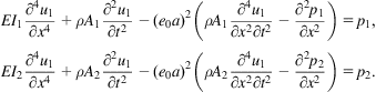 (7.15)
The wave propagation solution for CNTs can be expressed as
(7.16)
where Ui is the amplitude of the wave motion, k is the wave number, and ![]() is the frequency of the wave motion.
is the frequency of the wave motion.
The analytic solution can be obtained from the Euler–Bernoulli beam model,
(7.17)
 (7.17)
where
(7.18)
 (7.18)
The governing equation for DWCNT’s wave propagation by considering the vdW effect via the nonlocal Timoshenko beam model is given as [43]
(7.19)
 (7.19)
where pk (k=1, 2) is the vdW force between the adjacent tubes. The (inward positive) net radial pressure pk on the tube k is given as follows:
(7.20)
where cij is the vdW interaction coefficient, which is estimated as [24]
(7.21)
and
(7.22)
in which
(7.23)
Nonlocal beam theory can conform to the local theory if the scale coefficient e0 is set to zero.
In order to check the applicability of the dispersion relations by the nonlocal double-beam model, MD simulation for DWCNTs is also presented. The lengths of the DWCNTs are 19.7 nm. The interaction of atoms in each tube is described by the second-generation REBO potential energy expression for hydrocarbons [60], while the vdW force between inner and outer walls is described by the Lennard–Jones potential [72]. Poisson’s ratio and Young’s modulus calculated from the MD simulations for the test of axial tension are listed in Table 7.1.
7.3 Nonlocal Elastic Shell Model [73]
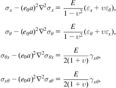
Based on Eq. (7.13), Hook’s law for the stress and strain relation in the polar coordinate system in nonlocal elastic shell model is expressed by
(7.24)
 (7.24)
where ![]() is the Young’s modulus of the material;
is the Young’s modulus of the material; ![]() is the Poisson’s ratio;
is the Poisson’s ratio; ![]() and
and ![]() are the longitudinal and angular circumferential coordinates;
are the longitudinal and angular circumferential coordinates; ![]() ,
, ![]() ,
, ![]() , and
, and ![]() are the normal and shear stresses; and
are the normal and shear stresses; and ![]() ,
, ![]() , and
, and ![]() are the normal and shear strains. The Laplace operator in the polar coordinate system is given by
are the normal and shear strains. The Laplace operator in the polar coordinate system is given by ![]() , and
, and ![]() is the radius measured from the mid-plane of the cross-section in the following CNT analysis.
is the radius measured from the mid-plane of the cross-section in the following CNT analysis.
The nonlocal elastic cylindrical shell theory, which is based on the Flugge shell theory [74], was developed by Wang and Varadan [44]. The application of the nonlocal elastic cylindrical shell theory to each tube of an armchair–armchair (10, 10)@(15, 15) DWCNT yields six equations that govern its free vibrations, as follows:
(7.25)
 (7.25)
where ![]() (k=1, 2) is the vdW force between the adjacent tubes. The (inward positive) net radial pressure
(k=1, 2) is the vdW force between the adjacent tubes. The (inward positive) net radial pressure ![]() on tube k is given by (7.20).
on tube k is given by (7.20).
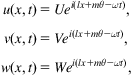
The wave propagation solution for CNTs can be expressed as
(7.26)
 (7.26)
where ![]() denote the longitudinal, circumferential, and radial displacement amplitudes of tube k, respectively. l is the wavenumber in the longitudinal direction, ω is the frequency of the wave motion. The proposed nonlocal Flugge shell theory in equations (7.25) can conform to the local theory if the scale coefficient,
denote the longitudinal, circumferential, and radial displacement amplitudes of tube k, respectively. l is the wavenumber in the longitudinal direction, ω is the frequency of the wave motion. The proposed nonlocal Flugge shell theory in equations (7.25) can conform to the local theory if the scale coefficient, ![]() a=0, is set to zero.
a=0, is set to zero.
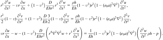
An important case results from considering motion independent of ![]() . Thus
. Thus ![]() .
.
(7.27)
 (7.27)
The second equation of (7.27) is uncoupled from the other two equations and represents the purely torsional motion of the shell. The pure torsional wave propagation solution for CNTs can be expressed as ![]() . Substituting the expression to the equation (7.25) leads to the velocity of torsion wave:
. Substituting the expression to the equation (7.25) leads to the velocity of torsion wave:
(7.28)
The material parameters of CNTs are proposed as: in-plane stiffness ![]() [13], mass density
[13], mass density ![]() .
.
Adams et al. [75] suggested the bending rigidity, D=1.62 eV, by applying the quantum MD methods using both empirical and local density functional methods to evaluate the energies of a number of ball-shaped and tubular fullerenes of various sizes. The bending rigidity D=1.46 eV was evaluated based on ab initio energy calculations by Kudin et al. [76]. The value of bending rigidity, D=2 eV, was proposed in a study in which the results of the phonon dispersion relations of a CNT were compared with those based on the local elasticity theory for a cylindrical medium [77]. Wang and Liew [11] proposed the bending rigidity 1.78 eV using Molecular mechanics calculations for relatively large tubes and graphite sheets. D=1.78 eV will be used in this study. The substitution of Eqs. (7.27) into Eqs. (7.25) ultimately yields a generalized eigenvalue problem, as follows.
(7.29)
 (7.29)
where the entries of matrices ![]() are functions of the wavenumbers
are functions of the wavenumbers ![]() and
and ![]() and the scale coefficient
and the scale coefficient ![]() . The condition for the existence of nonzero solutions
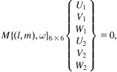
. The condition for the existence of nonzero solutions ![]() is
is
(7.30)
The six dispersion relations can be obtained by solving equation (7.30) for a given wavenumber m=2. The numerical results are shown in Fig. 7.4. One of them will be used to predict the dispersion of the transverse wave in an armchair–armchair (10, 10)@(15, 15) DWCNT.
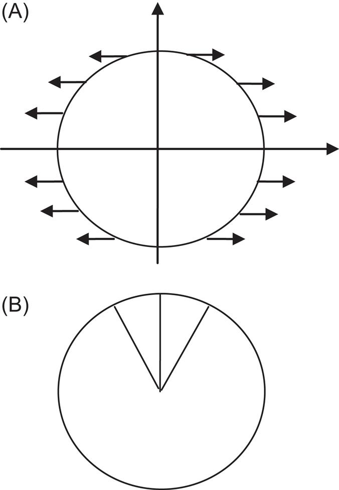
To check the applicability of the dispersion relations produced by the nonlocal cylindrical shell model to SWCNTs and DWCNTs, MD simulations are presented. The transverse and torsional wave can be produced when the atoms at the end of CNT are excited in a way showed in Fig. 7.5A and B, respectively. The lengths of SWCNTs and DWCNTs are about 19.7 nm. Using the second-generation REBO potential, we computed the Poisson’s ratio ![]() and Young’s modulus E=0.83 TPa for the armchair (10, 10) and (15, 15) CNTs that were derived from the MD simulation for the test of axial tension. The Poisson’s ratio
and Young’s modulus E=0.83 TPa for the armchair (10, 10) and (15, 15) CNTs that were derived from the MD simulation for the test of axial tension. The Poisson’s ratio ![]() and Young’s modulus E=0.8 TPa are calculated for the zigzag (20, 0) CNT.
and Young’s modulus E=0.8 TPa are calculated for the zigzag (20, 0) CNT.
7.4 Vibration Characteristics of CNTs [71]
Free transverse, longitudinal, and torsional vibrations of SWCNTs with different lengths and radii are investigated. Applicability of nonlocal models is verified by MD simulations.
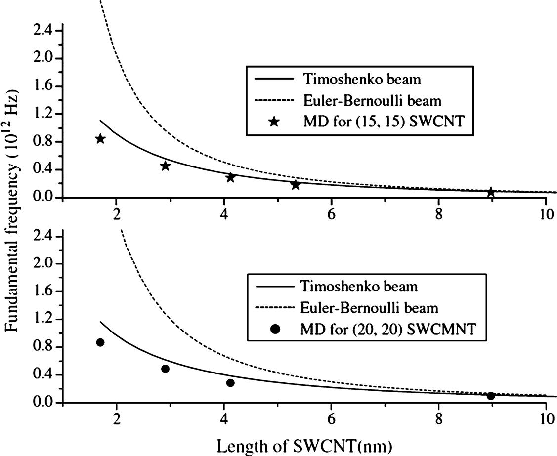
Figs. 7.6 and 7.7 show the fundamental frequencies of four cantilevered SWCNT with different lengths and radii. The fundamental frequency becomes lower when an SWCNT is longer. The Timoshenko beam model gives a better prediction of the fundamental frequency of shorter SWCNTs than the Euler–Bernoulli beam model does. Both beam models are appropriate for relative longer SWCNTs. For example, the two beam models can predict the fundamental frequencies of SWCNTs well when the length of a (5, 5) SWCNT is larger than 3.5 nm.

The MD results and beam models for free transverse vibration of clamped–clamped SWCNT are showed in Fig. 7.8. The fundamental frequency of the clamped–clamped SWCNT is higher than a cantilevered SWCNT with the same length. The fundamental frequency of transverse vibration of the clamped–clamped SWCNT can reach 1.06 terahertz for a (5, 5) SWCNT with the length of 2.91 nm.

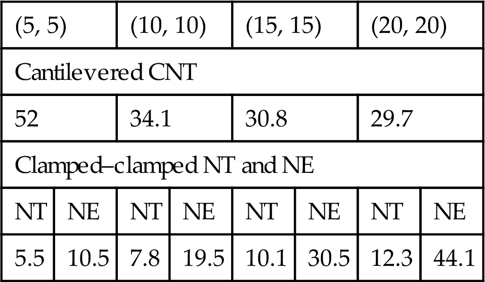
Figs. 7.6–7.8 indicate that the nonlocal Timoshenko beam model will not be necessary when the length of a CNT is longer than 3.5 nm. But the Timoshenko beam model is not effective to predict the frequencies from verifications by the MD results when the SWCNT is shorter, e.g., 1.7 nm long in Figs. 7.6–7.8 The values of parameter ![]() in the nonlocal Timoshenko beam and nonlocal Euler–Bernoulli beam models for different SWCNTs are list in Table 7.2. The boundary conditions have a significant effect on the value of parameter
in the nonlocal Timoshenko beam and nonlocal Euler–Bernoulli beam models for different SWCNTs are list in Table 7.2. The boundary conditions have a significant effect on the value of parameter ![]() . The parameter
. The parameter ![]() should be 52 to match the fundamental frequency obtained from MD simulation for cantilevered (5, 5) SWCNTs with length shorter than 3.5 nm.
should be 52 to match the fundamental frequency obtained from MD simulation for cantilevered (5, 5) SWCNTs with length shorter than 3.5 nm.
Table 7.2
The Parameter e0 in Nonlocal Timoshenko (NT) Beam and Nonlocal Euler (NE) Beam Models for Transverse Vibration of SWCNTs With Two Different Boundary Conditions [71]
| (5, 5) | (10, 10) | (15, 15) | (20, 20) | ||||
| Cantilevered CNT | |||||||
| 52 | 34.1 | 30.8 | 29.7 | ||||
| Clamped–clamped NT and NE | |||||||
| NT | NE | NT | NE | NT | NE | NT | NE |
| 5.5 | 10.5 | 7.8 | 19.5 | 10.1 | 30.5 | 12.3 | 44.1 |
Reprinted with permission from Hu YG, Liew KM, Wang Q. Nonlocal continuum model and molecular dynamics for free vibration of single-walled carbon nanotubes. J Nanosci Nanotechno 2011;11(12):10401–7. Copyright © American Scientific Publishers.
The parameter ![]() should be 5.2 for (5, 5) SWCNTs with both ends clamped. The nonlocal Euler–Bernoulli beam model fails to predict the fundamental frequency of short cantilevered SWCNTs because the fundamental frequency will not decrease with the increased parameter
should be 5.2 for (5, 5) SWCNTs with both ends clamped. The nonlocal Euler–Bernoulli beam model fails to predict the fundamental frequency of short cantilevered SWCNTs because the fundamental frequency will not decrease with the increased parameter ![]() . But the fundamental frequency of a clamped–clamped nonlocal Euler–Bernoulli beam decreases with the parameter
. But the fundamental frequency of a clamped–clamped nonlocal Euler–Bernoulli beam decreases with the parameter ![]() . In this case, the parameter should be 10.5 for a clamped–clamped nonlocal Euler–Bernoulli beam to match the MD results of (5, 5) SWCNT with length shorter than 3.5 nm.
. In this case, the parameter should be 10.5 for a clamped–clamped nonlocal Euler–Bernoulli beam to match the MD results of (5, 5) SWCNT with length shorter than 3.5 nm.
Fig. 7.9 shows the fundamental frequencies of longitudinal vibration of SWCNT with different lengths and boundary conditions. The rod model can be used to predict the MD results for long SWCNT. The fundamental frequency of longitudinal vibration of clamped–clamped SWCNT can reach 2.96 terahertz for (5, 5) SWCNT with 2.91 nm long.

Fig. 7.10 shows the torsional vibration of a cantilevered and clamped–clamped (5, 5) SWCNT. The fundamental frequencies can be predicted well by the rod model for long SWCNT. It is necessary to use the nonlocal rod model to predict the natural frequencies for short SWCNT, such as 1.7 nm long. The values of parameter![]() in nonlocal rod model for SWCNTs with lengths smaller than 3.5 nm are listed in Table 7.3. When the length is larger than 3.5 nm, the classical rod model can provide good predictions of fundamental frequency of free longitudinal and torsional vibrations of SWCNT.
in nonlocal rod model for SWCNTs with lengths smaller than 3.5 nm are listed in Table 7.3. When the length is larger than 3.5 nm, the classical rod model can provide good predictions of fundamental frequency of free longitudinal and torsional vibrations of SWCNT.
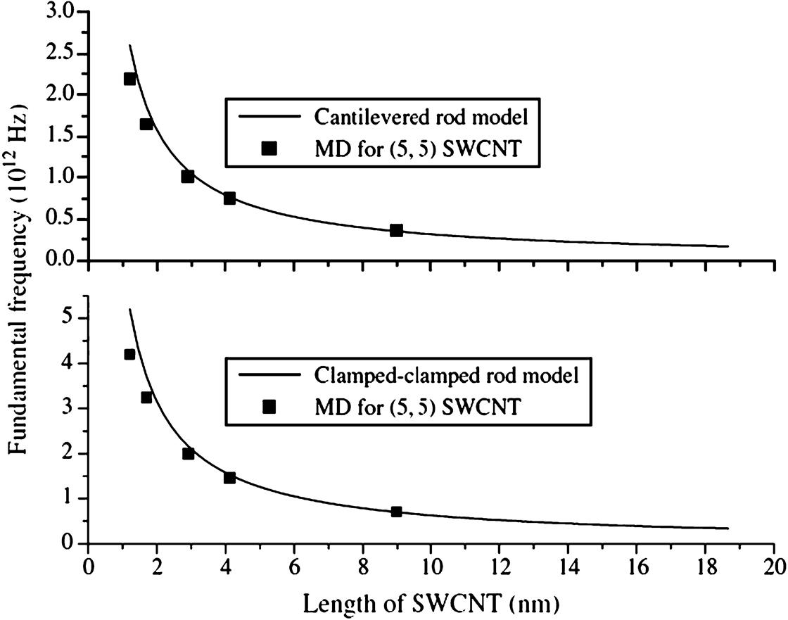
Table 7.3
The Parameter e0 in Nonlocal Rod Models for Longitudinal and Torsional Vibrations of SWCNTs With Two Different Boundary Conditions [71]
| SWCNT | Longitudinal Vibration | Torsional Vibration | ||
| Cantilevered | Clamped–Clamped | Cantilevered | Clamped–Clamped | |
| (5, 5) | 5.8 | 3 | 4 | 2.2 |
| (10, 10) | 5.8 | 3.1 | 3.8 | 2.3 |
| (15, 15) | 7.3 | 3 | 3.4 | 2.7 |
| (20, 20) | 7.7 | 2.3 | 3.3 | 2.8 |

Reprinted with permission from Hu YG, Liew KM, Wang Q. Nonlocal continuum model and molecular dynamics for free vibration of single-walled carbon nanotubes. J Nanosci Nanotechno 2011;11(12):10401–7. Copyright © American Scientific Publishers.
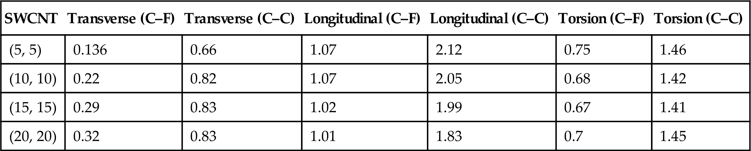
Table 7.4 shows the fundamental frequencies of SWCNTs with different boundary conditions and the length of 4.12 nm. The boundary conditions have a significant effect on the fundamental frequency. The symbols C–F and C–C in the table represent cantilevered and clamped–clamped boundary conditions, respectively. The clamped–clamped SWCNT’s fundamental frequency is higher than the cantilevered one. The fundamental frequency of longitudinal vibration of a clamped–clamped SWCNT is higher than others for the same SWCNT in Table 7.4.
Table 7.4
MD Results of the Fundamental Frequencies (1012 Hz) of SWCNTs With Different Boundary Conditions and the Same Length 4.12 nm [71]
| SWCNT | Transverse (C–F) | Transverse (C–C) | Longitudinal (C–F) | Longitudinal (C–C) | Torsion (C–F) | Torsion (C–C) |
| (5, 5) | 0.136 | 0.66 | 1.07 | 2.12 | 0.75 | 1.46 |
| (10, 10) | 0.22 | 0.82 | 1.07 | 2.05 | 0.68 | 1.42 |
| (15, 15) | 0.29 | 0.83 | 1.02 | 1.99 | 0.67 | 1.41 |
| (20, 20) | 0.32 | 0.83 | 1.01 | 1.83 | 0.7 | 1.45 |
Reprinted with permission from Hu YG, Liew KM, Wang Q. Nonlocal continuum model and molecular dynamics for free vibration of single-walled carbon nanotubes. J Nanosci Nanotechno 2011;11(12):10401–7. Copyright © American Scientific Publishers.
In summary, free transverse, longitudinal, and torsional vibrations of cantilevered and clamped–clamped SWCNTs are studied through nonlocal beam models, nonlocal rod models, and MD simulations. Nonlocal beam and nonlocal rod models for the free vibrations of SWCNTs are verified by MD simulations. The nonlocal Timoshenko beam model can predict MD results better than the classical beam model does for short SWCNTs. The nonlocal Euler–Bernoulli model can also predict the fundamental frequency of short clamped–clamped SWCNTs. The classical (local) beam and rod models can give good predictions of fundamental frequencies of long SWCNTs when the length is larger than 3.5 nm.
7.5 Wave Propagation of CNTs [40]
7.5.1 Nonlocal Elastic Beam Models for Flexural Wave Propagation
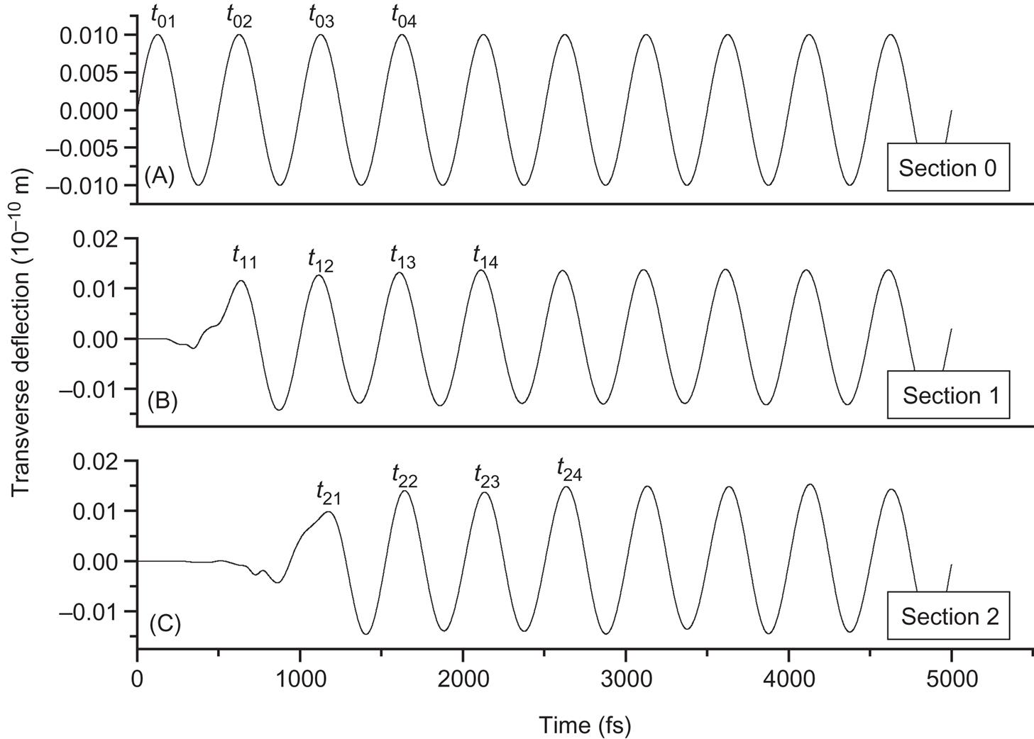
The phase velocity and wavenumber can be determined from the flexural vibration of two arbitrary sections of a CNT that is simulated using MD. The transverse displacement of some section of an armchair–armchair (10, 10)@(15, 15) DWCNT can be obtained by computing the average displacements of the atoms in the section. The harmonic deflection is achieved by shifting the edge atoms at one end of the CNT shown in Fig. 7.11. For example, the atoms that are located at the end of the armchair–armchair (10, 10)@(15, 15) DWCNT denoted by 0 are assumed to be subjected to a harmonic deflection of period T=500 fs, as shown in Fig. 7.12. The corresponding angular frequency is ![]() =2/T
=2/T ![]() 1.26
1.26![]() 1013 rad/s while the other end is kept free. Fig. 7.12B and C shows the flexural vibrations of 1 at x1=2.46 nm and 2 at x2=4.92 nm, respectively, of the DWCNT that is simulated using MD. If the transient deflection of the first two periods is neglected, then the propagation duration
1013 rad/s while the other end is kept free. Fig. 7.12B and C shows the flexural vibrations of 1 at x1=2.46 nm and 2 at x2=4.92 nm, respectively, of the DWCNT that is simulated using MD. If the transient deflection of the first two periods is neglected, then the propagation duration ![]() t of the wave from 1 to 2 can be estimated as
t of the wave from 1 to 2 can be estimated as
(7.31)
The phase velocity and wave number are expressed as follows, respectively,
(7.32)
One section of the inner tube and outer tube at period T=500 fs is presented in Fig. 7.13. The inner tube and outer tube are observed to vibrate coaxially in the figure.
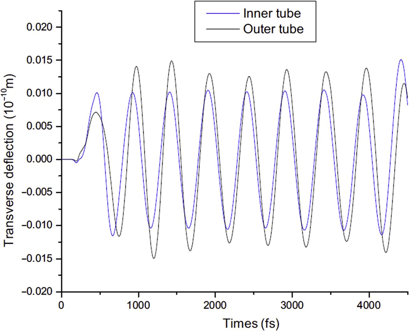
Fig. 7.14 illustrates the dispersion relations between the phase velocity c and the wave number k of the flexural wave in the (10, 10)@(15, 15) DWCNT. The flexural wave dispersion relation derived from the above governing equation for nonlocal double Euler–Bernoulli and Timoshenko beam models are showed in Fig. 7.14. The classical (or local) beam theories cannot reveal the small effect on flexural wave dispersion. The scale coefficients, e0=6.5 and a=0.142 nm, are used in the nonlocal elastic double Timoshenko beam model. When the wave number is approximately smaller than 1![]() 109 1/m, the phase velocities given by local or nonlocal beam models are close to each other and they can all predict the MD simulations well. When the wave number is larger than 1.5
109 1/m, the phase velocities given by local or nonlocal beam models are close to each other and they can all predict the MD simulations well. When the wave number is larger than 1.5![]() 109 1/m, the phase velocity decreases, and it is found that only the nonlocal elastic double Timoshenko beam model can predict the flexural wave dispersion of the DWCNT. Figs. 7.15 and 7.16 show the dispersion relation of flexural wave in (5, 5)@(10, 10) DWCNT and (10, 0)@(19, 0)DWCNT. It is clearly seen that only the nonlocal elastic double Timoshenko beam model can predict the flexural wave dispersion of the DWCNTs when the wave numbers are larger than 2.4
109 1/m, the phase velocity decreases, and it is found that only the nonlocal elastic double Timoshenko beam model can predict the flexural wave dispersion of the DWCNT. Figs. 7.15 and 7.16 show the dispersion relation of flexural wave in (5, 5)@(10, 10) DWCNT and (10, 0)@(19, 0)DWCNT. It is clearly seen that only the nonlocal elastic double Timoshenko beam model can predict the flexural wave dispersion of the DWCNTs when the wave numbers are larger than 2.4![]() 109 1/m and 2.44
109 1/m and 2.44![]() 109 1/m for (5, 5)@(10, 10) DWCNT and (10, 0)@(19, 0) DWCNT, respectively. The nonlocal Euler beam model fails to describe wave propagation in the DWCNTs. The values of the scale coefficient e0=4.3 and 6.1 are used in the nonlocal double Timoshenko beam model for the two DWCNTs. In addition, it is found that there are little differences among nonlocal models with different scale parameters e0 when the wave number is small. The good agreement between the dispersion relation induced from the nonlocal elastic double Timoshenko beam model and the MD simulations verifies the effectiveness of this model.
109 1/m for (5, 5)@(10, 10) DWCNT and (10, 0)@(19, 0) DWCNT, respectively. The nonlocal Euler beam model fails to describe wave propagation in the DWCNTs. The values of the scale coefficient e0=4.3 and 6.1 are used in the nonlocal double Timoshenko beam model for the two DWCNTs. In addition, it is found that there are little differences among nonlocal models with different scale parameters e0 when the wave number is small. The good agreement between the dispersion relation induced from the nonlocal elastic double Timoshenko beam model and the MD simulations verifies the effectiveness of this model.

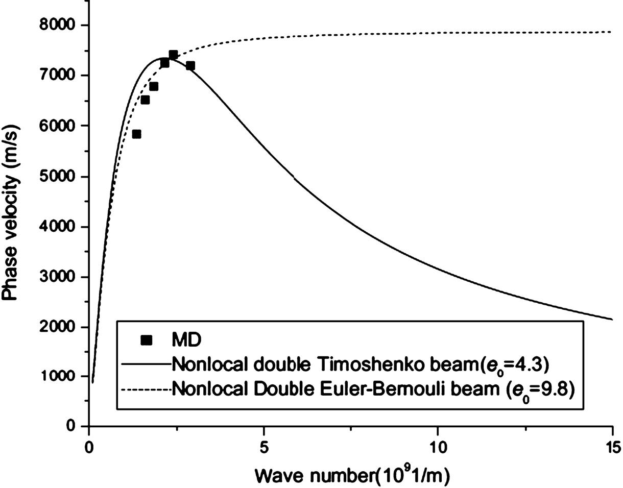
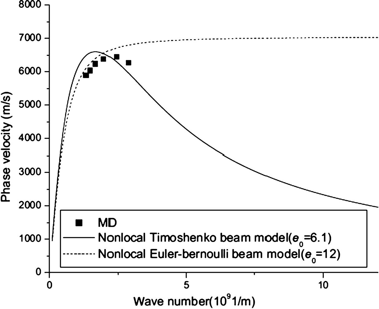
Fig. 7.17 provides the vibration of the (10, 10)@(15, 15) DWCNT at the period T=330 fs and the corresponding angular frequency is ![]() =2/T≈1.9
=2/T≈1.9![]() 1013 rad/s. From the figure, it shows that when the frequency is larger than 1.9
1013 rad/s. From the figure, it shows that when the frequency is larger than 1.9![]() 1013 rad/s, a noncoaxial vibration of the DWCNT will occur. The average phase difference between the inner tube and the outer tube can be estimated from Fig. 7.17 as
1013 rad/s, a noncoaxial vibration of the DWCNT will occur. The average phase difference between the inner tube and the outer tube can be estimated from Fig. 7.17 as ![]() . In order to check the effect of the vdW force on the noncoaxial vibration of the DWCNT, MD simulations for flexural wave in SWCNTs are conducted. Fig. 7.18 indicates that the (10, 10) and (15, 15) SWCNTs have different phases at the period T=330 fs without considering the vdW forces between them. The average phase difference between the (10, 10) and (15, 15) SWCNTs can also be estimated from Fig. 7.18
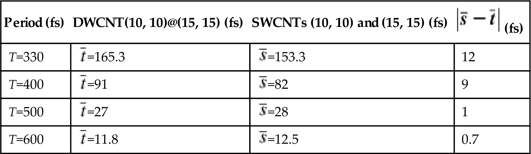
. In order to check the effect of the vdW force on the noncoaxial vibration of the DWCNT, MD simulations for flexural wave in SWCNTs are conducted. Fig. 7.18 indicates that the (10, 10) and (15, 15) SWCNTs have different phases at the period T=330 fs without considering the vdW forces between them. The average phase difference between the (10, 10) and (15, 15) SWCNTs can also be estimated from Fig. 7.18 ![]() . The other average phase differences at different periods are shown in Table 7.5. The phase difference of the vibration becomes increasingly obvious with the decrease in the period. The phase difference increases from 11.8 to 165.3 fs as the period decreases from 600 to 330 fs for DWCNTs. Similarly, the phase difference increases from 12.5 to 153.3 fs as the period decreases from 600 to 330 fs for SWCNTs. The values of
. The other average phase differences at different periods are shown in Table 7.5. The phase difference of the vibration becomes increasingly obvious with the decrease in the period. The phase difference increases from 11.8 to 165.3 fs as the period decreases from 600 to 330 fs for DWCNTs. Similarly, the phase difference increases from 12.5 to 153.3 fs as the period decreases from 600 to 330 fs for SWCNTs. The values of ![]() and
and ![]() are very close at the periods T=500 fs and T=600 fs, at which the phase velocity also starts to decrease, as indicated in Fig. 7.14. It is concluded that the different small-scale effects of SWCNTs with different diameters have a significant effect on the noncoaxial flexural vibration of DWCNTs at high frequency. The vdW forces make no significant contribution to the phase differences, as the noncoaxial vibration of DWCNTs would occur without consideration of the vdW forces between the adjacent tubes. The continuum mechanics model is inapplicable in the analysis of flexural wave in DWCNT when the noncoaxial vibration of DWCNTs happens at high frequency, especially when the angular frequency is larger than 1.9
are very close at the periods T=500 fs and T=600 fs, at which the phase velocity also starts to decrease, as indicated in Fig. 7.14. It is concluded that the different small-scale effects of SWCNTs with different diameters have a significant effect on the noncoaxial flexural vibration of DWCNTs at high frequency. The vdW forces make no significant contribution to the phase differences, as the noncoaxial vibration of DWCNTs would occur without consideration of the vdW forces between the adjacent tubes. The continuum mechanics model is inapplicable in the analysis of flexural wave in DWCNT when the noncoaxial vibration of DWCNTs happens at high frequency, especially when the angular frequency is larger than 1.9![]() 1013 rad/s.
1013 rad/s.
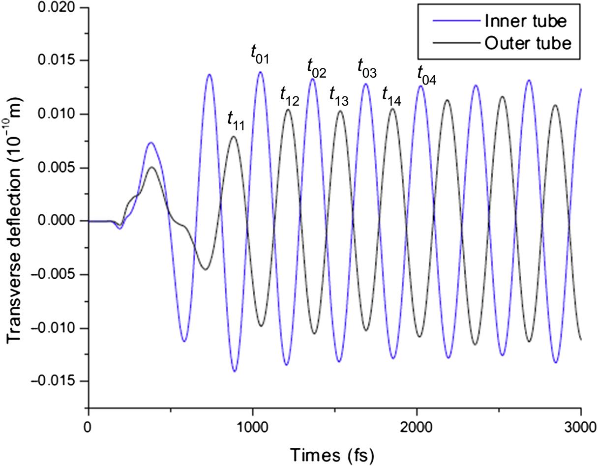

Table 7.5
Average Phase Differences of the Vibration of the Section Which Is 2.46 nm Ahead of the End of the DWCNT (10, 10)@(15, 15) and the SWCNTs (10, 10) and (15, 15) [40]
| Period (fs) | DWCNT(10, 10)@(15, 15) (fs) | SWCNTs (10, 10) and (15, 15) (fs) | |
| T=330 | 12 | ||
| T=400 | 9 | ||
| T=500 | 1 | ||
| T=600 | 0.7 |
In summary, the study of flexural wave dispersion in DWCNTs in a wide range of wavenumbers by the nonlocal elastic double-beam theory and MD simulations is presented. The results indicate that only the nonlocal elastic double Timoshenko beam model is able to predict the small effect on flexural wave dispersion when the wavenumber becomes so large that the CNT microstructure plays an important role in the flexural wave. These small-scale effects have a significant effect on the noncoaxial flexural vibration of DWCNTs at high frequency. The vdW interaction has little effect on the noncoaxial flexural vibration of DWCNT, and the nonlocal elastic Timoshenko beam theory is inapplicable in modeling the noncoaxial wave propagation in CNTs.
7.5.2 Nonlocal Shell Model for Elastic Wave Propagation
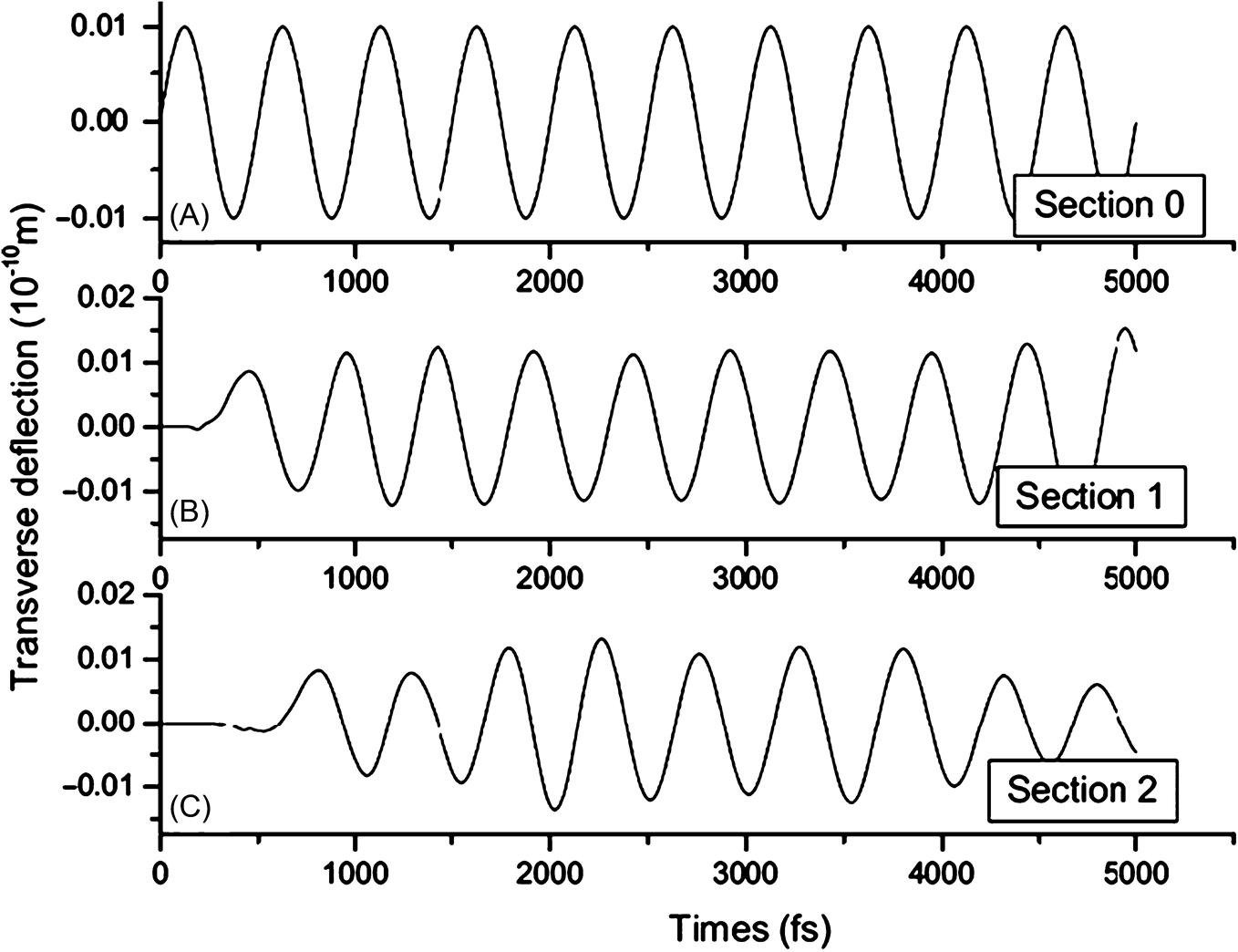
It is quite straightforward to determine the phase velocity and wavenumber from the transverse vibration of atoms in two arbitrary sections of a CNT that was simulated using MD. The harmonic deflection of some atoms was achieved by shifting the atoms at one end of the nanotube while the other end was kept free, as shown in Fig. 7.5A. For example, some atoms that are located at the end of the armchair (15, 15) SWCNT denoted by Section 0 were assumed to be subject to the harmonic deflection of period ![]() , as shown in Fig. 7.19A. The corresponding angular frequency is
, as shown in Fig. 7.19A. The corresponding angular frequency is![]() . Fig. 7.19B and C show the transverse vibrations of the atom in Section 1 at x1=2.46 nm and Section 2 at x2=4.92 nm, respectively. If the transient deflection of the first two periods is neglected, then the propagation duration
. Fig. 7.19B and C show the transverse vibrations of the atom in Section 1 at x1=2.46 nm and Section 2 at x2=4.92 nm, respectively. If the transient deflection of the first two periods is neglected, then the propagation duration ![]() of the wave from Section 1 to Section 2 can be estimated as
of the wave from Section 1 to Section 2 can be estimated as
(7.33)
 input at section 0. (B) The deflection of section 1, 2.46 nm ahead of section 0. (C) The deflection of section 2, 4.92 nm ahead of section 0 [73].
The phase velocity and wavenumber are, respectively,
(7.34)
When the atoms at the end of CNT are subjected to the harmonic excitation indicated in Fig. 7.5B, the torsional wave will propagate in SWCNTs as shown in Fig. 7.20. The torsional wave velocity can be calculated through the method for calculating transverse wave velocity.
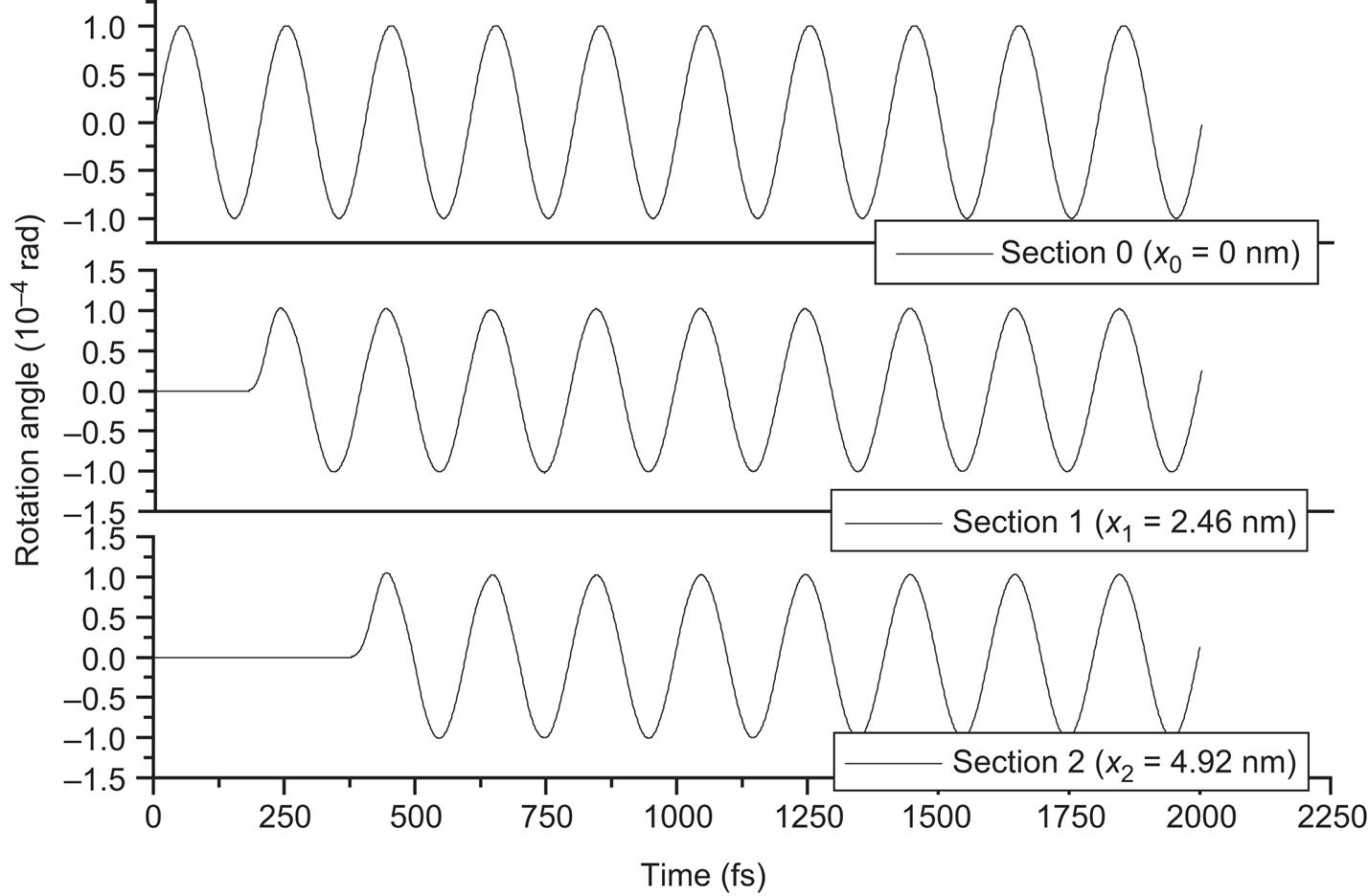
Fig. 7.21 illustrates the dispersion relations between the phase velocity ![]() and the wavenumber k of the transverse wave in the armchair (15, 15) SWCNT and zigzag (20, 0) SWCNT. Fig. 7.21 shows the nonlocal shell model can predict the MD results better than the local shell model can when the wave lengths are less than
and the wavenumber k of the transverse wave in the armchair (15, 15) SWCNT and zigzag (20, 0) SWCNT. Fig. 7.21 shows the nonlocal shell model can predict the MD results better than the local shell model can when the wave lengths are less than ![]() and
and ![]() for (15, 15) SWCNT and (20, 0) SWCNT, respectively. The value of the parameter
for (15, 15) SWCNT and (20, 0) SWCNT, respectively. The value of the parameter ![]() =0.6 is used for transverse wave in armchair (15, 15) and zigzag (20, 0) CNT.
=0.6 is used for transverse wave in armchair (15, 15) and zigzag (20, 0) CNT.
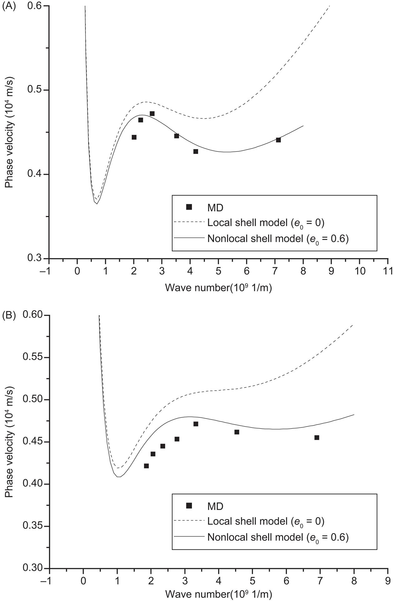
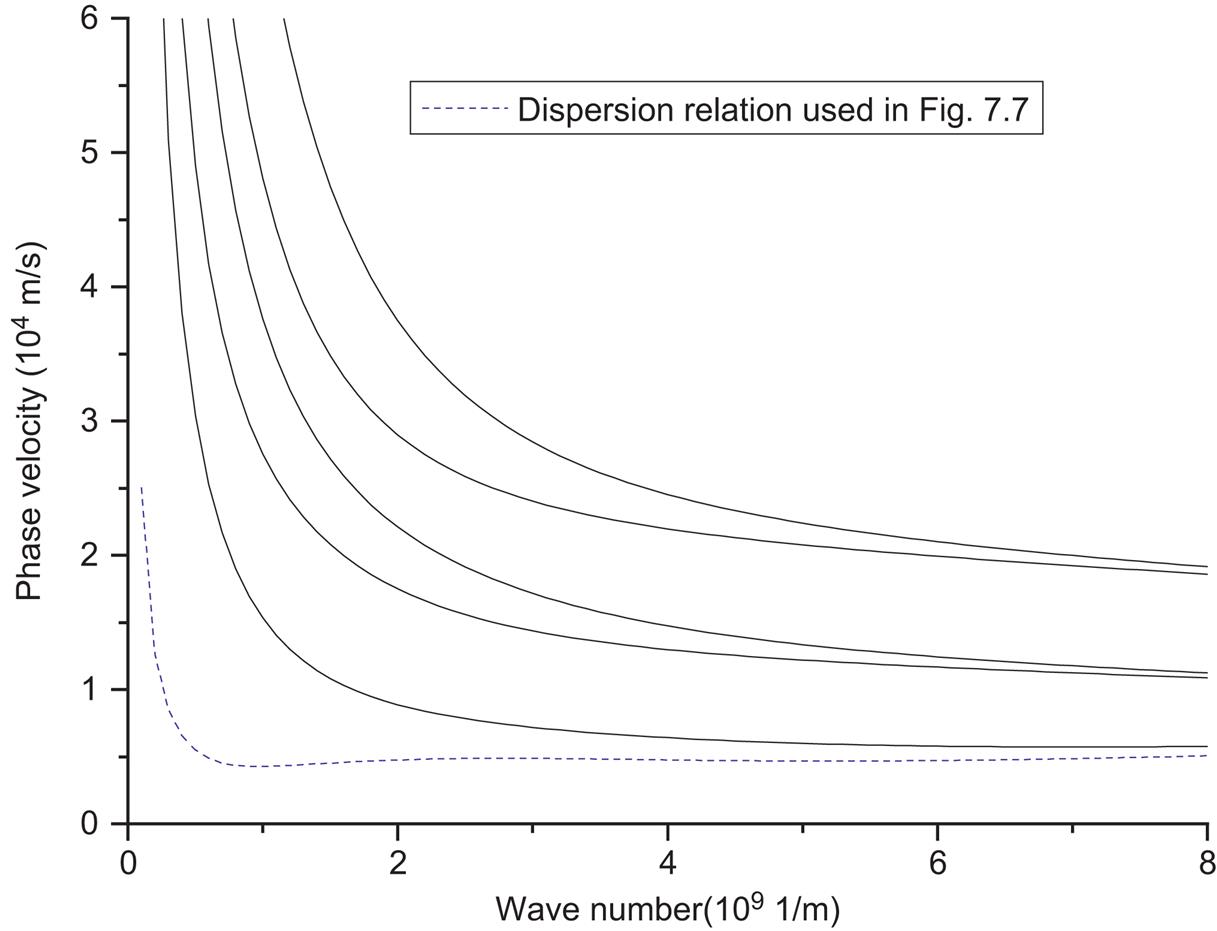
Fig. 7.22 shows that the nonlocal elastic cylindrical double-shell model can predict the dispersion relation of the transverse wave better than local double-shell model when the wavenumber is large enough. This is because the interlayer van der Waals interaction of the DWCNT and the small-scale effect on the dispersion of the transverse wave of the SWCNT are considered. The phase velocity decreases when the wavenumber is approximately larger than ![]() 1/m, or the wavelength is approximately less than
1/m, or the wavelength is approximately less than ![]() . The nonlocal elastic double-shell model can predict the wave dispersion better than local shell model when the wavelength is approximately smaller than
. The nonlocal elastic double-shell model can predict the wave dispersion better than local shell model when the wavelength is approximately smaller than ![]() . Fig. 7.23 indicates that the nonlocal shell model can predict dispersion relation obtained from the MD simulation of torsional wave in (10, 10) SWCNT and (15, 15) SWCNT better than local shell model can when the wavelength is smaller than
. Fig. 7.23 indicates that the nonlocal shell model can predict dispersion relation obtained from the MD simulation of torsional wave in (10, 10) SWCNT and (15, 15) SWCNT better than local shell model can when the wavelength is smaller than ![]() and
and ![]() , respectively. The good agreement between the nonlocal elastic cylindrical shell models results and the MD simulations verifies the effectiveness of this model. The value of the parameter
, respectively. The good agreement between the nonlocal elastic cylindrical shell models results and the MD simulations verifies the effectiveness of this model. The value of the parameter ![]() =0.6 is adopted for (10, 10)@(15, 15) DWCNTs to predict the dispersion of a transverse wave in CNTs, and
=0.6 is adopted for (10, 10)@(15, 15) DWCNTs to predict the dispersion of a transverse wave in CNTs, and ![]() =0.2 and 0.23 are used for a torsional wave in SWCNT (10, 10) and SWCNT (15, 15), respectively. The estimates of
=0.2 and 0.23 are used for a torsional wave in SWCNT (10, 10) and SWCNT (15, 15), respectively. The estimates of ![]() are investigated through the comparison between the dispersion relations obtained from numerical results of equations and MD simulation. The value of
are investigated through the comparison between the dispersion relations obtained from numerical results of equations and MD simulation. The value of ![]() which is a coefficient to identify the scale effect should be different for different issues, such as dispersions of different elastic waves in SWCNT and DWCNT. The scale coefficient is dependent on SWCNTs and DWCNTs for transverse wave, and CNTs for torsional wave. When the value of
which is a coefficient to identify the scale effect should be different for different issues, such as dispersions of different elastic waves in SWCNT and DWCNT. The scale coefficient is dependent on SWCNTs and DWCNTs for transverse wave, and CNTs for torsional wave. When the value of ![]() becomes smaller, the scale effect will be weaker. The torsional wave motion is only related to the displacement in tangential direction, while the transverse wave motion is involved in the displacements in longitudinal, radial, and tangential direction. The carbon atoms more complicated vibration in the transverse wave propagation in CNT leads to the stronger scale effect on the dispersion of the transverse wave. This is the main reason why the vale of
becomes smaller, the scale effect will be weaker. The torsional wave motion is only related to the displacement in tangential direction, while the transverse wave motion is involved in the displacements in longitudinal, radial, and tangential direction. The carbon atoms more complicated vibration in the transverse wave propagation in CNT leads to the stronger scale effect on the dispersion of the transverse wave. This is the main reason why the vale of ![]() =0.2 for the torsional wave in SWCNT is much smaller than the values of
=0.2 for the torsional wave in SWCNT is much smaller than the values of ![]() =0.6 used for transverse wave in CNTs. The structure of CNTs, such as chirality, diameter, and layers, may also be the factors to affect the value of
=0.6 used for transverse wave in CNTs. The structure of CNTs, such as chirality, diameter, and layers, may also be the factors to affect the value of ![]() . But for the same problems, such as transverse wave or torsional wave, in CNT, these structure differences lead to a relatively small change of the value of
. But for the same problems, such as transverse wave or torsional wave, in CNT, these structure differences lead to a relatively small change of the value of ![]() compared to the changes of values for different problems.
compared to the changes of values for different problems.
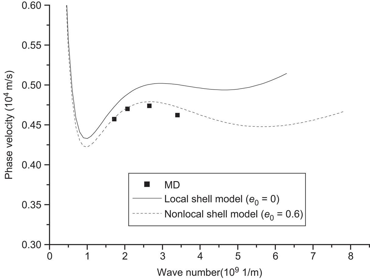

Fig. 7.24 indicates that the obvious phase difference of inner and outer tube of the (10, 10)@(15, 15) DWCNT will occur at the period T=300 fs. The corresponding angular frequency is ![]() rad/s. The average phase difference between the inner tube and the outer tube can be estimated from Fig. 7.8 as
rad/s. The average phase difference between the inner tube and the outer tube can be estimated from Fig. 7.8 as ![]() . Fig. 7.25 indicates that the SWCNTs (10, 10) and (15, 15) have different phases at the period T=300 fs without considering the van der Waals forces between them. The average phase difference between the SWCNTs (10, 10) and (15, 15) can also be estimated from Fig. 7.25:
. Fig. 7.25 indicates that the SWCNTs (10, 10) and (15, 15) have different phases at the period T=300 fs without considering the van der Waals forces between them. The average phase difference between the SWCNTs (10, 10) and (15, 15) can also be estimated from Fig. 7.25: ![]() fs. The other average phase differences at different periods are shown in Table 7.6. The phase difference of the vibration becomes increasingly obvious with the decrease of the period. The phase difference increases from 43.3 to 103.2 fs as the period decreases from 700 to 300 fs for DWCNTs. Similarly, the phase difference increases from 40 to 101.2 fs as the period decreases from 700 to 300 fs for SWCNTs. The van der Waals forces make no significant contribution to the phase differences of the transverse wave in the inner and outer tube, as the phase differences would occur without consideration of the van der Waals forces between the adjacent tubes. This indicates that the small-scale effects can change the phase when the frequency is extremely high.
fs. The other average phase differences at different periods are shown in Table 7.6. The phase difference of the vibration becomes increasingly obvious with the decrease of the period. The phase difference increases from 43.3 to 103.2 fs as the period decreases from 700 to 300 fs for DWCNTs. Similarly, the phase difference increases from 40 to 101.2 fs as the period decreases from 700 to 300 fs for SWCNTs. The van der Waals forces make no significant contribution to the phase differences of the transverse wave in the inner and outer tube, as the phase differences would occur without consideration of the van der Waals forces between the adjacent tubes. This indicates that the small-scale effects can change the phase when the frequency is extremely high.

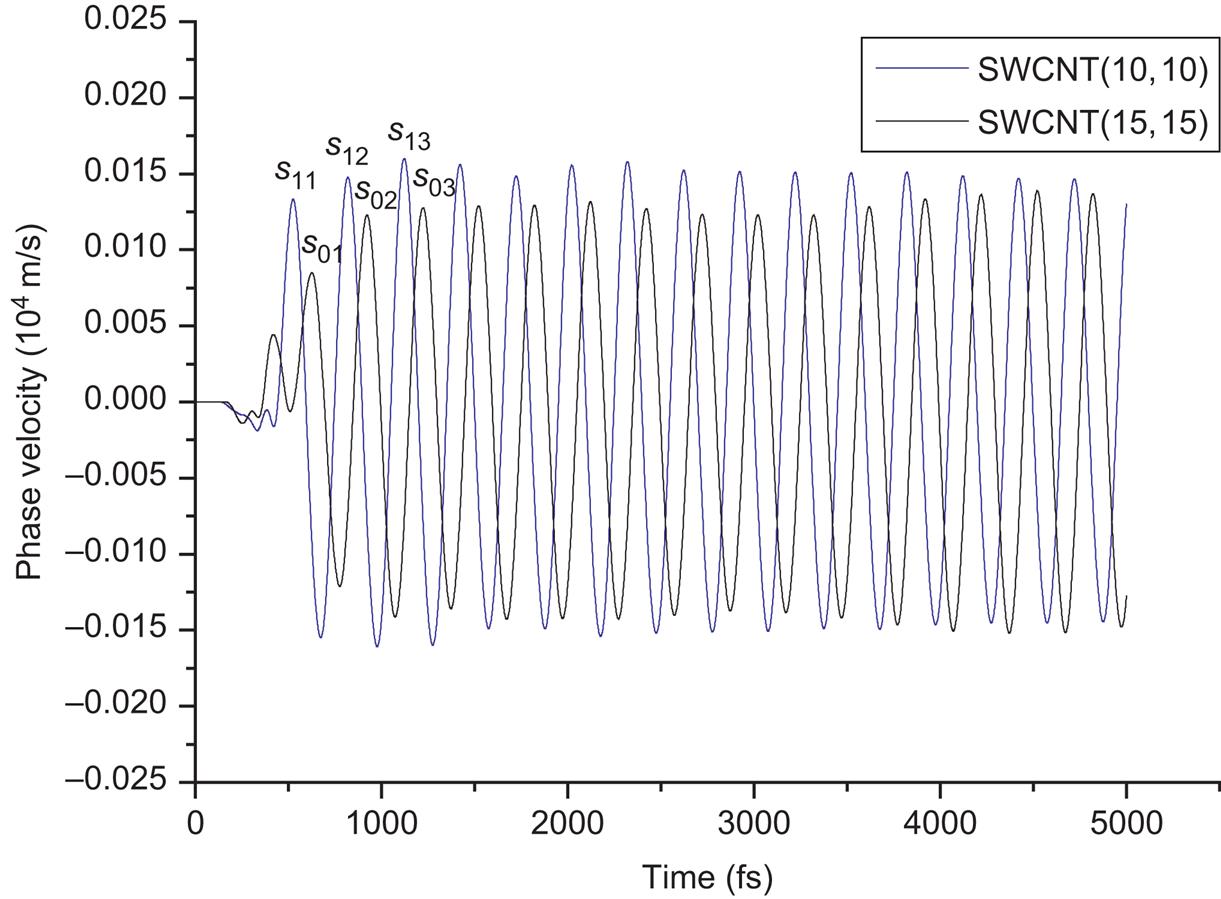
Table 7.6
The Average Phase Differences of the Vibrations of Atom at the Section, 2.46 nm Ahead of the End of the DWCNT (10, 10)@(15, 15) and the SWCNTs (10, 10) and (15, 15) [73]
| Period (fs) | DWCNT (10, 10)@(15, 15) (fs) | SWCNTs (10, 10) and (15, 15) (fs) | | |
| T=300 | 2 | ||
| T=400 | 6.2 | ||
| T=500 | 21 | ||
| T=600 | 25 | ||
| T=700 | 3.3 |

In summary, the study of transverse and torsional wave dispersion in SWCNTs and DWCNTs on the basis of the nonlocal elastic cylindrical shell theory and the use of MD simulations for SWCNT and an armchair–armchair (10, 10)@(15, 15) DWCNT in a wide range of wavenumbers are presented. The value of parameter ![]() is estimated based on the MD result to predict the dispersion of a transverse wave in CNTs through using the nonlocal shell models. The results of this study indicate that the nonlocal elastic cylindrical shell model is able to offer a better prediction for transverse and torsional wave dispersion in CNTs than the local elastic shell model when the wavenumber is large enough. The nonlocal shell models are required when the wavelengths are approximately less than
is estimated based on the MD result to predict the dispersion of a transverse wave in CNTs through using the nonlocal shell models. The results of this study indicate that the nonlocal elastic cylindrical shell model is able to offer a better prediction for transverse and torsional wave dispersion in CNTs than the local elastic shell model when the wavenumber is large enough. The nonlocal shell models are required when the wavelengths are approximately less than ![]() and
and ![]() for a transverse wave in armchair (15, 15) SWCNTs and a torsional wave in armchair (10, 10) SWCNTs, respectively. These small-scale effects have a significant effect on the phase difference of a transverse wave in the inner and outer tubes of DWCNTs at high frequency.
for a transverse wave in armchair (15, 15) SWCNTs and a torsional wave in armchair (10, 10) SWCNTs, respectively. These small-scale effects have a significant effect on the phase difference of a transverse wave in the inner and outer tubes of DWCNTs at high frequency.