
Chapter 18
High-Speed Filters
Abstract
High-speed op amps have given rise to high-speed band-pass filters. While the design techniques remain the same, the open-loop response of the op amp gives rise to some interesting, but troubling, limitations to what can be done in the design of an active filter.
Keywords
Frequency shift; Gain compression; High-speed filters; Open-loop response
18.1. Introduction
Once the exclusive domain of passive filters and discrete components, op amps have progressed to the point where they can be considered for high-frequency filter design. At high speeds, however, filter design gets particularly challenging. The main limitation of high-speed op amp filter design comes from the op amp open-loop bandwidth. You may remember how the open-loop bandwidth affects op amp gain circuits from Section 7.6. The effect of open-loop gain on filters, however, begins lower in frequency and can produce very nonintuitive–nonworking filters. If you love challenges, high-speed filter design will test the limits of what you can do with analog filters, with the foreknowledge that things will start to get strange!

18.2. High-Speed Low-Pass Filters
Reviewing Fig. 18.1, which is repeated from earlier in the book.
It is immediately obvious that the general shape of the open-loop response plot is that of a low-pass filter. Therefore, if the low-pass breakpoint is not terribly critical, all you have to do is to select an op amp with a unity gain bandwidth at the desired −3 dB breakpoint! Imagine explaining to a manager how the low-pass filter actually is identical to a unity gain stage. The high-speed low-pass filter can also have gain—it will lower the −3 dB breakpoint by approximately a decade for each 20 dB of gain.
Obviously in the case of low-pass filters, you got off very easily. This will not be the case for the remainder of filter responses!
18.3. High-Speed High-Pass Filters
There is no such thing as an active high-pass filter with good reason. The gain/bandwidth product of the op amp used will ultimately produce a low-pass response characteristic, making this a wide band-pass filter. It is your responsibility to choose an op amp with a frequency limit well above the bandwidth of interest. This is doubly so at high speeds, because you are inevitably closer to the open-loop limitation of the op amp.
You will need to select an op amp that has sufficient open-loop response that it will pass the bandwidth of interest before it starts rolling off due to open-loop gain limitations.
18.4. High-Speed Band-Pass Filters
This is where things get really interesting, because the physics of an op amp can and will actually force the resonant peak off frequency (lower) and erode the peak. You may be asking how can this be? The capacitors and resistors are supposed to define the center frequency of the filter, they will not change with frequency. This is a valid question, and it leads to the answer—the frequency shift is coming from the op amp itself. But again why?
The answer comes from the location of the open-loop response characteristic of the op amp—which is the ultimate speed limit of the op amp at any frequency. A band-pass filter is composed of both low-pass and high-pass elements, and the high pass characteristics will tend to get chopped off as they approach the open-loop characteristic. This will appear as first an amplitude limitation and finally as a frequency shift as the bandwidth limitation of the high-pass elements comes into play and limits the point at which they interact with the low-pass filter elements. The result is a truncated response that appears to be a frequency shift.

To illustrate this effect, band-pass filters were constructed using the topology of Section 17.3.3. The results are shown in Fig. 18.2.
Three frequencies were constructed, indicated by the sets of peaks above. For 10 MHz, the third set of peaks, a Q (and gain) of 1, the open-loop response of the op amp was a little over 30 dB above the peak at 10 MHz, and the filter actually worked very well. As the Q (and gain in V/V) was raised in steps of 5, however, things began to change. By the time a Q of 25 was attempted, the gain of the filter was almost back to unity, and the frequency shifted to the left to about 6.5 MHz! Clearly, the proximity of the open-loop response was affecting the op amp. Even the attempts to make a 1 MHz band-pass filter—although not showing the undesirable frequency shift—still show an amplitude compression effect. Only the 100 kHz filter shows anything close to lab results matching theoretical.
Note that the open-loop response of this particular op amp indicates that it is approximately a 1 GHz op amp, in other words close to the state of the art in op amp design! Therefore, there is a practical limit to how fast a band-pass filter can be constructed, about 10 MHz for unity gain and Q of 1. That limit is about 1/100 the rated bandwidth of the op amp. If a higher Q is desired, say 10, then the practical limit is about 1/1000 the rated bandwidth of the op amp. In other words,
This limitation may also hit lower-frequency band-pass filters—be extremely careful! I can assure the reader—this bandwidth limitation has hit more than one time in my career, and the reader is warned that these effects on filter center frequency can occur differently in different batches of the same op amp and may only appear at certain temperatures. Unlike the stability criteria discussed in Chapter 6, there is little or no warning when this effect is about to show up, it is similar to falling off a cliff in the dark! Leave a generous safety margin when designing high-frequency band-pass filters, because the effects of insufficient op amp bandwidth can occur unexpectedly and dramatically. One board may work, another board may not. One layout may work, another layout may not. Even a fairly low-frequency band-pass filter may require a very fast op amp to accommodate higher values of Q. You have two choices if you encounter this limit—either select an op amp with a higher gain/bandwidth product or lower the Q of the band-pass filter. The time to anticipate this is before a product is produced, not after it has failed in the field!
18.5. High-Speed Notch Filters
A very similar bandwidth restriction affects notch filters. Instead of eroding the amplitude of the peak and/or shifting it in frequency as it does band-pass filters, the bandwidth restriction erodes the depth of the notch. A notch filter was constructed using the techniques of Section 17.3.5. A 1 GHz bandwidth op amp was used, for a filter center frequency of 1 MHz. No tuning of center frequency was attempted. Various values of Q were attempted, with the following results (Fig. 18.3).
Obviously, the center frequency is largely unaffected, it is the Q that takes a hit. At a Q of 1, a 30 dB notch is possible at 1 MHz. However, higher Q's only erode the depth of the notch. The circuit as constructed is completely unsuitable for a Q greater than 1.

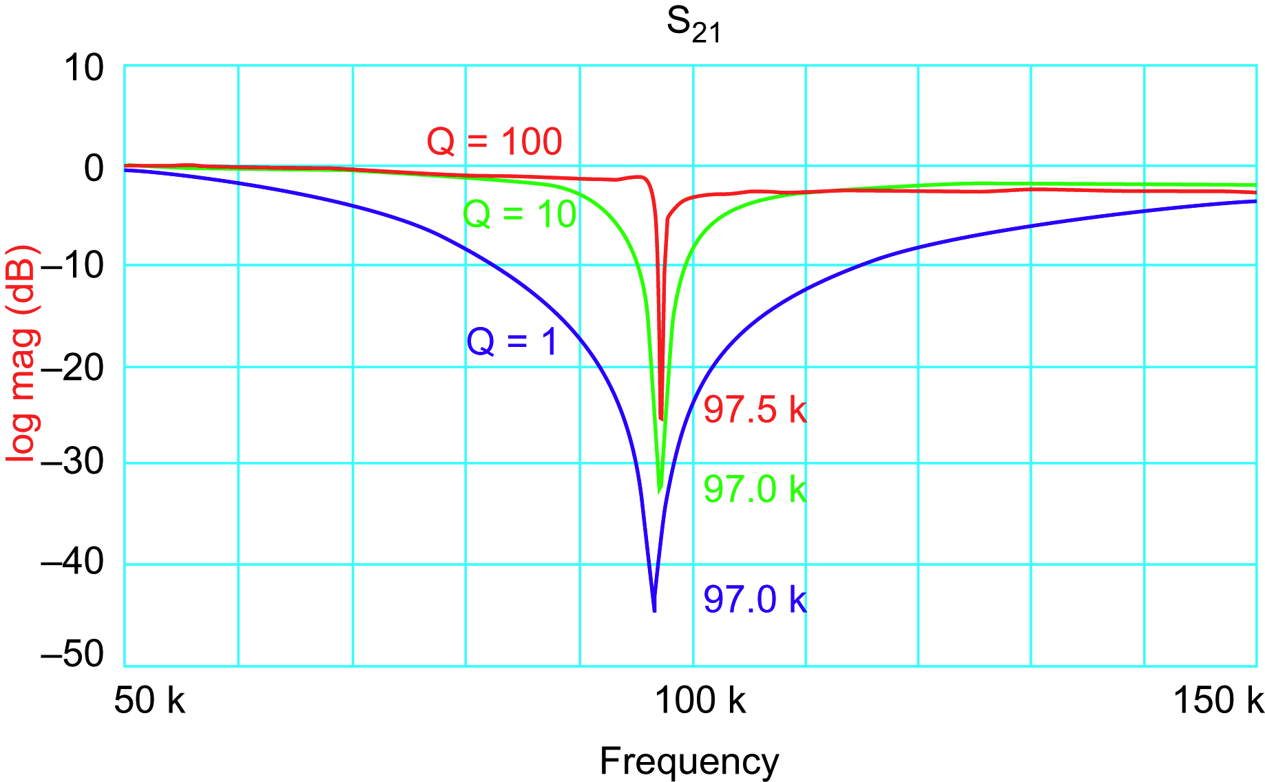
The circuit was retuned for a center frequency of 100 kHz, and the results below were measured (Fig. 18.4).
Notch depth erosion is even evident at 100 kHz. At this point, it is clear that even a 1 GHz op amp can only be used to construct notch filters at 1 MHz and a Q of 1 and 100 kHz with a Q of 10 or so. This amazing degree of limitation was totally unexpected, to say the least!
18.6. 10 kHz Notch Filter Results
The results above were so dramatic that I thought I would retune the circuit for a center frequency of 10 kHz to see what the results might be. This is the resulting response for a Q of 100 and a Q of 10 (Fig. 18.5).

Incredibly, the bandwidth of a 1 GHz op amp is still affecting the Q, even at 10 kHz. That is 5 decades of frequency!
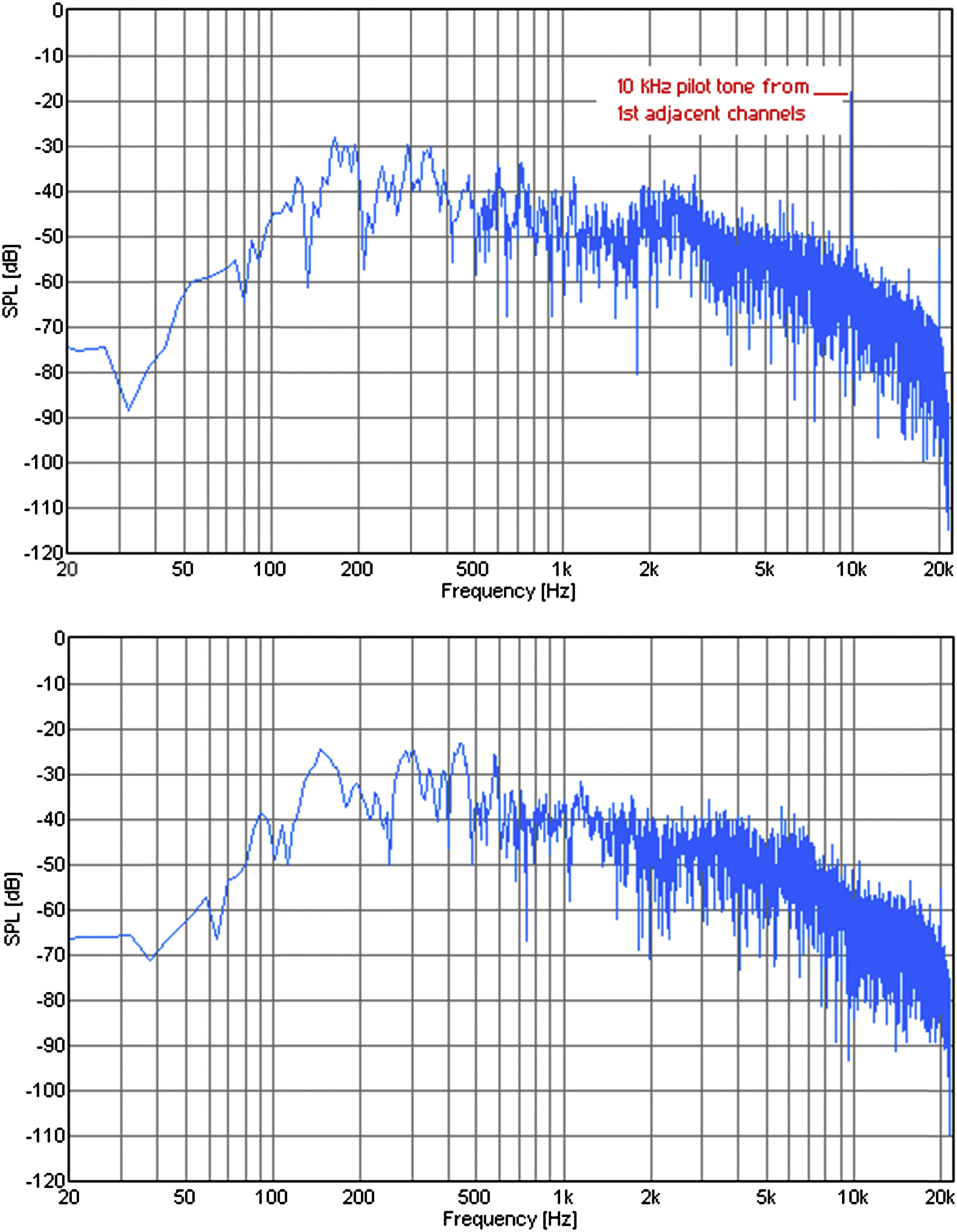
A good application for 10 kHz notch filters is amplitude modulation (medium wave) receivers, where the carrier from adjacent stations produces a loud 10 kHz whine in the audio, particularly at night. This is a real ear-full and can really grate on one's nerves when listening for a prolonged time. Fig. 18.6 shows the received audio spectrum of a station before and after the 10 kHz notch was applied. Note that the 10 kHz whine is the loudest portion of the received audio, although the human ear is less sensitive to it. This audio spectrum was taken at night on a local station, which had two strong stations on either side. FCC regulations allow for some variation of the carrier of stations. Therefore, slight errors in carrier frequency of the two adjacent stations will make the 10 kHz tones heterodyne, increasing the unpleasant listening sensation. When the notch filter is applied in the bottom plot of Fig. 18.6, the 10 kHz tone is reduced to the same level as surrounding modulation. Also visible on the audio spectrum are 20 kHz carriers from stations two channels away and a 16 kHz tone from a transatlantic station. These are not a problem, because they are attenuated substantially by the receiver IF. A frequency of 20 kHz is inaudible to the vast majority of people in any event.
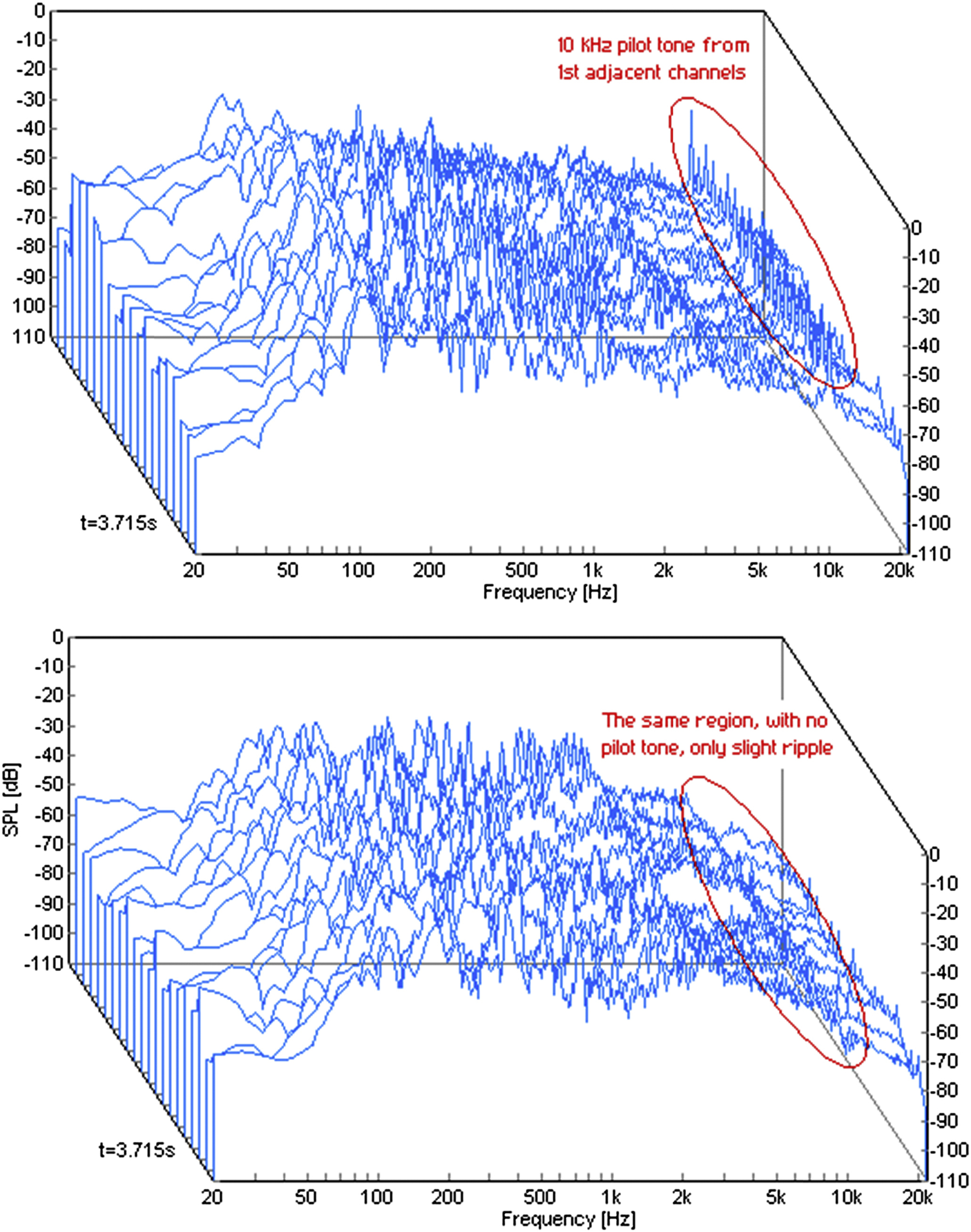
Fig. 18.7 shows the same spectrum on a waterfall diagram. In this case, the sample window is widened, and the 10 kHz carrier interference is shown as a string of peaks which vary in amplitude. When the notch is applied, the 10 kHz peaks are eliminated, and there is only a slight ripple in the received audio where 10 kHz has been notched out.
18.7. Conclusions
High-speed filter design is a new frontier—the state of the art of op amps is barely adequate. If proper care is taken, the results can be good. But the designer is cautioned once again—the open-loop bandwidth of an op amp has much more of a limiting effect on an op amp used in a filter configuration than it does on an op amp that is merely used for gain. Especially in the case of band-pass and notch filters, the circuit design must be overly cautious and rigorously tested.
..................Content has been hidden....................
You can't read the all page of ebook, please click here login for view all page.