
34.6.5 Summary
What is Discussed in the above
The physical principles of the operation of a PMBDCM have been discussed which lead to the development of the necessary parts of a power electronic controller. One specific type of current control, hysteresis band current control was explained in detail, and one specific type of switch logic pattern was developed. The exposition has included many of the issues that can cause difficulties for controller designers if they are not careful.
What is Not Discussed in the above
Many PMBDCMs have more than one pair of poles. The arguments above can all be extended to higher pole count machines, by taking any mention of degrees to be electrical degrees rather than mechanical degrees. The controller discussed in detail only manages one direction of rotation. It is an excellent exercise, and straightforward, but not trivial, to repeat the above steps, preparing the tables for clockwise rotation of the simple machine discussed above. Then, following the discussion in the first part of Section 34.6.3, Current/Torque Control about H bridge switching, prepare the logic tables again for full bidirectional control, using the I up and I down logic signals exactly as above, but applying them to both “legs” determined by the rotor position. Only one form of current sensing was discussed in detail. There are many simpler schemes in use which do not have quite the flexibility and accuracy of the above, but which can suit certain applications. Similarly, there are other forms of current control such as the constant-frequency linear method briefly discussed. Shaft position sensors take many forms. Adherence to the HE sensor was for simplicity, and to reinforce the magnetic field aspects of the machine operation.
34.7 Servo Drives
34.7.1 Introduction
Servo drives are motor drives that operate with high dynamic response. Historically, servo drives have implied motion-control systems in which sophisticated motor design, drive, and control techniques have been employed to obtain very much shorter positioning times than is possible with conventional drive systems. Examples are in machine tool drives, robotic actuators, computer disk drives, and so on. The power range for these drives has typically been in the range of a few kilowatts or less. This range has steadily increased in recent years as a result of advances in magnetic materials, machine design, power and signal electronic devices, and sensors.
Apart from the fast positioning times, “high dynamic response” also means that the drive operates with the following:
The last of the foregoing items is brought about by robust and intelligent control algorithms; the first two items are brought about by innovative and often costly motor and controller designs. As a result of these, the cost of a servo motor drive is usually much higher than the equivalent power rated industrial drives.
The distinctions just mentioned may be easily recognized by noting, for example, that the drives that bring material to a mill may not require high performance, but the drives that take part in shaping, milling, or reducing the material should have high dynamic response in order to increase throughput and meet the accuracy requirements of the final product.
34.7.2 Servo Drive Performance Criteria
The performance of a servo drive can be expressed in terms of a number or factors such as servo bandwidth, accuracy, percentage regulation, and stiffness. While servo bandwidth indicates the ability of the drive to track a moving or cyclic reference, the percentage regulation and stiffness stipulates the drive's static holding performance for speed or position, in the face of disturbances from the load and in the supply conditions. The servo bandwidth, specified as a frequency in Hertz or rad/sec, is often found from the system frequency response plot, such as the Bode diagram.
The percentage regulation of a speed-controlled system often refers to the percentage change in speed from no load to full load. In a type-zero system, this figure will have a finite value. Many systems are type zero, albeit with a high gain so that the regulation is acceptably low. For such systems, the regulation is often necessary for operational reasons. In some applications, zero percentage error is required, which calls for type 1 or integral type control system.
The servo stiffness is similar to the percentage error mentioned earlier, but it applies mainly for the position servo. It specifies the deflection of the load from its reference position, when full load torque is applied. It is usually the slope of the deflection versus the applied load torque in rad/Nm around the reference position.
34.7.3 Servo Motors, Shaft Sensors, and Coupling
Servo drives use motors which allow the desired goals of high dynamic response to be achieved. The important parameters/attributes of a servo motor are:
1. High torque-to-inertia ratio,
2. High torque-to-volume ratio,
3. Low inductance of the motor windings,
4. Low cogging torque at low speed,
5. Efficient heat dissipation,
6. Low coefficient of shaft compliance,
7. Direct-coupled, high-resolution, shaft-mounted sensors for position and speed.
High torque-to-inertia ratio allows fast acceleration or deceleration of the drive when motion references are changed. This is often achieved through innovative low-inertia rotor design and low inductance in the stator winding. One example of a dc servo motor is the pancake printed armature dc motor with no iron in the rotor, as indicated in Fig. 34.70. The rotor is sandwiched between axially mounted stator poles. The commutator is also on the printed armature. Another example is the disk rotor stepping motor, also without iron in the rotor, as indicated in Fig. 34.71.

FIGURE 34.70 Pancake armature of a de servo motor. Courtesy: Printed Motors Ltd., UK.
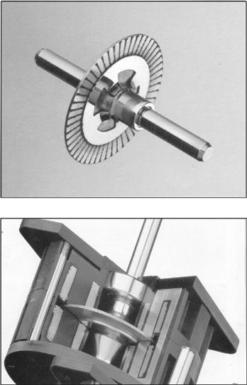
FIGURE 34.71 A disk rotor stepping motor with ironless rotor for low inertia and inductance. Courtesy: Escap Motors.
The PM ac synchronous motors with modern high-energy-density magnets in the rotor, as described in Section 34.6, are also examples where the motor designer strives to minimize the rotor inertia. Modern permanent magnets allow the required airgap flux to be developed with a much reduced volume of the magnets, consequently reducing the diameter of the rotor.
It is well-known that the moment of inertia of a motor increases as the fourth power of its outer radius!
Another benefit of the modern permanent-magnet material is that the motor volume is also reduced. Servo motors often have to be located in a very confined space, and this reduction in volume is an important attribute.
The ironless designs mentioned earlier bring other benefits in the form of reduced inductance and cogging torque. Brushed pancake ironless motors are available with armature inductance as low as 100 μH.
From Section 34.2.2, the mechanical and electrical time constants of a brushed dc motor are given by
and ![]()
It is well known that for the highest load acceleration, the load inertia referred to the motor should be equal to the rotor inertia. Thus, in a matched system, the total inertia the motor accelerates is twice its own inertia. In other words, the motor inertia should also be minimized.
For a good servo motor, the ratio between the mechanical and the electrical time constants is often of the order of five or more. This allows the speed and the current-control loops to be decoupled and noninteracting. The electrical time constant of a motor determines how quickly the motor current may be changed and hence how quickly the torque can be changed. As also mentioned in Section 34.2, drives with a reasonable dynamic performance should have an inner torque loop. This torque loop is built around current loops, for the armature for the brushed dc motor, or for the d- and q-axes currents for the induction and synchronous motor drives. Having a low inductance in the winding allows these currents to be followed dynamically changing current or the torque references with higher accuracy and bandwidth.
The cogging torque, if appreciable, causes the rotor to have preferential positions. As a result, the position accuracy of the motor may suffer. Another problem is the ripple in speed as the motor is operated at low speed. At high speed, these ripples due to cogging torque may be filtered out by the motor inertia; however, the extra loss due to cogging remains. The ironless or toothless rotor obviously produce very small cogging torque because of the absence of preferential paths for the airgap flux to establish through the rotor iron of the brushed dc motor. The surface-magnet synchronous motor also has this feature. The interior-magnet motor normally has skewed stator slots to avoid the production of cogging torque.
Servo motors often operate with frequent start-and-stop duty, with the fastest allowable acceleration and deceleration during which the motor current is allowed to reach about 2–3 times the continuously rated current. The increased I2 Rloss in such duty must be dissipated. This calls for adequate cooling measures to be incorporated in the motor housing. With such operation, it is sometimes possible to excite the mechanical resonance due to shaft compliance. This is avoided through proper arrangement of the shaft position/speed sensor and the coupling between the motor and the sensor. A belt-driven speed sensor may be acceptable for an industrial drive; however, for servo applications, a rigid, direct-coupled sensor mounted as close as possible to the motor armature is preferable. Additionally, the speed sensor is also required to have negligible noise. Speed signal from analog tachogenerators, which were used for speed sensing until recently, invariably needed to be filtered to remove the cyclic ripple/noise that existed. Such filtering often limits the maximum speed-control bandwidth of a drive.
34.7.4 The Inner Current/Torque Loop
The inner current loop(s) in a servo motor drive play a more important role than just limiting the current in case of overload. These loops operate continuously to regulate the motor-developed torque so as to meet the load demand, and for meeting the speed trajectory specified by the motion controller. Motor drives of high dynamic response currently employ PWM current sources. These sources use MOSFET or IGBT switching devices that allow the modulator to be operated with a switching frequency between 10 and 25 kHz. At these frequencies, the inherent switching delay, which is equivalent to half of the PWM switching period, is made rather small for the bandwidth of the torque control loop. The bandwidth of the current control loops closely represents the bandwidth of the torque control. This is because the motor-developed torque generally is proportional to these currents. Servo drives up to a few kilowatts presently have torque/current control-loop bandwidths in excess of 1 kHz.
For higher power, fast-response drives, such as those used in the metal-processing industries, thyristor converters have been used for many years. The switching frequencies of these converters are rather low, being some multiple of the mains frequency, according to the converter chosen. Fortunately, the larger mechanical time constant of the larger power motor and the nature of the applications have allowed the 300 Hz (360 Hz in the United States) switch frequency of the three-phase thyristor bridge converter to be used satisfactorily in many applications requiring high dynamic response. The growing availability of faster and higher power IGBT devices is continually enhancing the dynamic performance of larger drives.
Fast-response, inner torque control loops have in recent years been extended to ac induction and synchronous motors. These motors were hitherto considered only for industrial drives. The vector methods described in Sections 34.3 and 34.4, which employ inner quadrature axis current controllers in the synchronous (for the induction motor) or the rotor (for the synchronous motor) reference frame, have transformed the prospects of ac motor drives in servo applications.
Because of the fast dynamic response requirement of servo drives, the servo motor is nearly always driven with the maximum torque per ampere (MTPA) characteristic. Field weakening is normally not used. In other words, field control either directly for a brushed dc motor or a synchronous motor or indirectly through armature reaction (i.e. through id current control) for induction or PM ac synchronous motors is not used for field weakening. It is nevertheless used for regulating the field at the desired level. Field weakening are mainly used for drives where the operation at higher than base speed with constant-power characteristic is desirable.
34.7.5 Sensors for Servo Drives
Servo drives require high-bandwidth current sensors for the inner torque loop and high-accuracy, noise-free speed and position sensors for the outer loops. The current sensor is often a Hall device with an amplifier, which can have band-widths as high as 100 kHz. The inner current loop both limits and continuously regulates the motor current in all operating modes of the drive, including acceleration and deceleration. About 2–3 times, the continuous rated current of the motor is tolerated during acceleration and deceleration. This entails limiting the speed controller output to the level corresponding to the current sensor output for the limiting values of motor currents.
The current-sensor output has to be filtered to adequately remove the switching frequency noise. Otherwise, certain switching devices in converter may be overloaded. This task is more important for the thyristor converters for dc drives for which the switching frequency is rather low. This filtering of the current-sensor output limits the bandwidth of the current-control system, i.e. the inner torque-control loop.
Performance of servo-motor drives depends critically on the noise and accuracy of the speed and position sensors. Synchro-resolvers with 12 bit or higher digital accuracy were used in many servo-drive systems until recently. The advent of cheaper incremental and absolute optical encoders has altered this situation completely. These digital sensors are actually position sensors. The speed information is derived from positions measured by discrete differentiation. Such differentiation is not feasible with analog position sensors, because of the noise.
Analog tachogenerators are also avoided for speed servo systems. This is because of the tachogenerator ripples inherent in the sensor.
Modern discrete position sensors provide for virtually noise-free speed and position sensing. This allows very fast dynamic response to be achieved if the switching frequency of the converter allows it.
34.7.6 Servo Control-loop Design Issues
34.7.6.1 Typical Controllers
34.7.6.1.1 Proportional Controller
A proportional controller provides for a straight gain to amplify the error signal. It has no discriminatory properties. With the input and feed-resistance values indicated in Fig. 34.72, the total gain of the controller is (K + 1).

FIGURE 34.72 Proportional controller.
34.7.6.1.2 Transient Velocity Feedback Controller
It is well-known that a following error will exist in the preceding system when a moving or ramp reference is tracked. If a rate feedback, such as the speed feedback in a position-control system, is used to damp the system, this error is further increased. To overcome this following error due to velocity feedback, transient velocity feedback can be used as indicated in Fig. 34.73.

FIGURE 34.73 Transient velocity feedback controller.
The speed (velocity) signal is passed through an RC circuit at the input of the amplifier circuit. An input current occurs only when the speed signal changes. In the steady state, the capacitor is fully charged, so that no following error in the steady state due to the velocity feedback can exist.
In the steady state when the velocities are equal, the output may lag or lead depending on the relative values of R1 and R2.·It can be shown that in the absence of frictional load torque, as is often the case in servo applications, no following error is introduced if R1 = R2.
34.7.6.1.3 Integral Controller
In the transient-velocity and error-rate feedback schemes, the following error will exist if viscous friction and load torque are present. If such loads are present, the system gain has to be infinity to have a zero error. Very large gains will make any physical systems unstable, unless bandwidth limitations exist. One way to employ infinite gain in the steady state is to use an integrator. This amplifies the steady-state error until it is eliminated.
Normally, a proportional plus integral (PI) action is used. A derivative term is normally not used in the control system of a drive system, since the drive feedback signals are very noisy. Instead, derivative signals are obtained through sensors such as tachogenerators. The structure of a PI controller is indicated in Fig. 34.74.

FIGURE 34.74 Integral controller.
It can be shown that there will be no steady-state error even in the presence of frictional or other load torque.
Many types of more complex controllers are available, such as the variable structure controller. Drives with fuzzy controllers have also been in the marketplace for some years.
The controller circuits just described are usually implemented in analog circuits using operational amplifiers. Digital implementations are also being gradually introduced using the embedded microcontrollers and digital signal processors.
34.7.6.2 Simplified Drive Representations and Control
Consider the block diagram of Fig. 34.75 in which the individual elements (blocks) are represented in terms of their transfer functions in terms of the Laplace operators.

FIGURE 34.75 Block diagram of a speed-control system.
Here, GA(s), GC(s), GL(s), HT(S), and HF(s) represent the transfer functions of the power converter plus the motor, the controller, the load, the sensor (of speed in this example), and the filter following the sensor respectively. The reference input for speed and the feedback signal are connected to a summing junction of an operational amplifier through resistors Ri and Rf, respectively.
The preceding system can be simplified to that shown in Fig. 34.76, and further to that in Fig. 34.77.

FIGURE 34.76 Simplified representation of Fig. 34.75.

FIGURE 34.77 Further simplified representation of Fig. 34.75.
In general, if the individual control blocks are approximated as first-order systems and are mutually decoupled, meaning that each block operates in a frequency band that is far outside the frequency bands of all other blocks, then the foregoing systems can be represented by a transfer function of the form
When T3 and T4 are much smaller time constants than T1 and T2, the preceding may be approximated by
where Ts = T3 + T4 + … etc. A dc-motor speed-control system with current and speed sensors falls in this category. For such a system there exist two dominant time constants (poles).
For such a system, a proportional plus integral controller is of the form
One optimization criterion (Kessler's) stipulates that τ1 ≈ T1, τ2 ≈ T2, and τ0 ≈ 2KTs. With this stipulation, the transfer function of the complete system is given by
Note that the two filter time constants τF1 and τF2 are included in Gc(s) for the sake of its realizability. These can be relegated to frequencies far higher than the range of interest and can be ignored for further analysis of the system. For an unit step input of Vi, the output V is given by
A typical output is sketched Fig. 34.78.

FIGURE 34.78 Response of the optimized system of Fig. 34.75.
If the transfer function G1(s) has one dominant time constant T1(s), as for the field current control of a dc motor, a suitable controller is the form
In some cases, the transfer function G1(s) is of the form
where Ts is the sum of a number of short time constants, associated with sensors, switching frequency, and so on. The current controller of the dc motor with back-emf has such a characteristic. A suitable PI controller for this system is
For this system, Kessler's optimization criterion stipulates that
The transfer function of the complete system is then
The peak overshoot of this system to a unit step unit is usually unacceptable, as indicated by the response of Fig. 34.79. This overshoot is usually reduced by inserting a first-order filter in the reference circuit. The filter network and the responses are given in Fig. 34.80.

FIGURE 34.79 Block diagram representation of a typical current controller.

FIGURE 34.80 Optimized response of the system of Fig. 34.80.
34.8 Stepper Motor Drives
34.8.1 Introduction
A stepper motor is a positioning device that increments its shaft position in direct proportion to the number of current pulses supplied to its windings. A digital positioning system without any position or speed feedback is thus easily implemented at a much lower cost than with the other types of motors, simply by delivering a counted number of switching signals to the motor. Typically, a 200 steps-per-revolution stepper motor with 5% stepping accuracy will be equivalent to a dc motor with a 12-bit (or 4000 counts/rev) encoder plus the closed-loop speed and position controllers for obtaining similar positioning resolution. This advantage, however, is obtained at a cost of increased complexity of the drive circuits. A disadvantage of the motor is perhaps its inability to reach an absolute position, since the final position reached is only relative to its arbitrary initial position. Nevertheless, the true digital nature of this motor makes it a very suitable candidate for digital positioning systems in many manufacturing, automation, and indexing systems.
The working principle of stepper motors is based on the tendency of the rotor to align with the position where the stator flux becomes maximum (i.e. seeking of the minimum-reluctance position, also called the detent position). The rotor and the stator are both toothed structures, and the stator normally has more than two windings to step the rotor in the desired direction when they are energized in certain combinations with current. Some motors additionally have permanent magnets embedded in the rotor that accentuate an already existing, zero-excitation detent torque. These motors hold their positions even when the stator excitations are removed completely, a feature desirable for some applications.
In addition to the point-to-point stepping action, these motors can also be operated at high slewing speed, simply by increasing the pulsing rate of phase currents. Since the motor is inherently a synchronous actuator, the pulsing rate has to be increased and decreased properly, so that the rotor may follow it. At the end of a complete run, the motor always stops at the desired incremental position or angle without any accumulated error. The only error that may be encountered is mainly due to the machining accuracy of the teeth in the stator and rotor. This error is of the order of about 5% of one step position/angle and it is nonaccumulative.
34.8.2 Motor Types and Characteristics
34.8.2.1 Single-stack Variable-reluctance Stepper Motor
Single-stack motors are normally of the variable-reluctance type with no excitation in the rotor. The cross section of a three-phase motor with two stator poles/phase and four rotor poles are indicated in Fig. 34.81. The motor can be stepped clock or anticlockwise by energizing the phase winding in the ABCA or ACBA sequence, respectively. The step angle, i.e. the angle moved by the rotor for each change in excitation sequence, of the motor is given by

FIGURE 34.81 Cross section of a single-stack variable-reluctance stepper motor.
where N is the number of phases in the stator and P is the number of poles in the stator. Single stack motors typically has larger step angles than other types because of limitations of space for the windings. The step angle of these motor tend to be larger than the multistack and hybrid stepper motors.
For each excited winding, the motor develops a torque angle (T–θ) characteristic as indicated in Fig. 34.82. Note that there are two equilibrium positions of the rotor, namely, X and Y, where the motor develops zero torque.

FIGURE 34.82 Static torque characteristic of a stepper motor.
The position X is referred to as the stable detent position, around which the rotor develops a restoring torque when displaced. The restoring torque increases as the rotor is moved from its detent position, becoming a maximum Tmax on either side of this position. The slope of the T–θ characteristic around this detent position and the maximum torque, both of which depend on the level of excitation, indicate how far the rotor will be displaced under load torque. This means that the level of excitation also affects the position holding accuracy of the motor.
The motor may also be excited in the sequence: AB–BC–CA or AB–CA–BC for forward and reverse stepping, respectively. The two phases-on scheme develops more torque around the detent positions at the expense of twice the resistive losses.
Yet another excitation scheme is AB–B–BC–C–CA–A–AB for forward stepping and AB–A–AC–C–BC–B–AB for reverse stepping. In this scheme, the step size is halved as opposed to the full-step size of the previous sequences. Two different levels of torque is produced for alternate detent positions. However, the reduced step size and the more damped nature of each step may outweigh this disadvantage.
34.8.2.2 Multi Stack Variable-Reluctance Stepping Motor
In a multi stack variable-reluctance motor, the stator windings are stacked along the shaft. Each stack section now has the same number of poles in the stator and the rotor. Normally each stator stack is staggered with respect to its neighbor by one/Nth of a pole pitch, where N is the number of stator/rotor phases or sections. The cut out view of Fig. 34.83 shows some internal details of a six-phase multi stack motor, in which each stack has a phase winding between two rings, each with 32 stator and rotor poles. The step size of this motor is
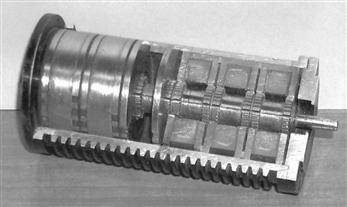
FIGURE 34.83 Cut out view of a six-phase, multi stack, variable-reluctance stepper motor. Courtesy: Pratt Hydraulics, UK.
The excitation sequence of this motor is similar to the ones mentioned in Section 34.8.2.1, except that more excitation sequences are available. When a stator winding is energized, the rotor poles of that section tend to align with those defined by the stator excitation. The stator and rotor teeth in the other sections are not aligned. By changing the combination of excited phases to the next in sequence, the rotor is made to move by one step angle.
34.8.2.3 Hybrid Stepping Motor
A hybrid stepper motor has an axially oriented permanent magnet sandwiched between two sections of the stator and rotor, as indicated in Fig. 34.84. The magnetic flux distributes radially through the two stator and rotor sections, both of which are toothed, and axially through the back iron of the stator and the shaft. The stator has two phase windings, each of which creates alternate polarities of magnetic poles in both sections of the stator. Stator windings are excited with bipolar currents, as opposed to the unipolar currents in the variable-reluctance motors of the two preceding sections. The magnetic flux produced by the stator windings is circumferential in each stator and rotor section, but also crosses the airgap radially. It does not, however, pass through the rotor magnet. The two rotor sections are offset by half its tooth pitch.

FIGURE 34.84 Axial section of the hybrid motor.
The rotor magnet causes to the stator and rotor teeth to settle at the minimum reluctance position with a modest amount of detent torque to keep the rotor in position, when the stator windings are not energized. The rotor magnetic flux distributes outward through stator poles 3 and 7 in section X and inward through poles 1 and 5 in section Y, as shown in Figs. 34.85a and b. When the stator windings A and B (indicated as dark and faint shaded, respectively) are energized with positive and negative currents, respectively, the resulting stator flux also distributes through these same poles, so that the rotor then develops a much higher detent torque (T–θ) characteristic. The motor can be stepped forward or backward by energizing windings in sequence ![]() or
or ![]() respectively, where the over bar indicates the polarity of currents in phases A and B.
respectively, where the over bar indicates the polarity of currents in phases A and B.

FIGURE 34.85 Cross section of the hybrid motor: (a) section X and (b) section Y.
The stepping angle of a hybrid stepper motor is given by
where P is the number of rotor poles.
34.8.2.4 Permanent-magnet Stepping Motor
Permanent-magnet stepper motors have alternate polarities of permanent magnets on the rotor surface while the rotor iron, if it is used, has no teeth. In one type of construction, the rotor has no iron, and the stator consists of two windings that setup alternate poles when energized, just as in the case of the hybrid motor. The rotor consists of permanent magnets, alternately polarized, attached to the surface of a nonmagnetic disk, as shown in Fig. 34.86. The stator and rotor fluxes cross the airgap, one on either side of the disk, axially

FIGURE 34.86 Rotor of a PM stepper motor. Courtesy: Escap Motors.
34.8.3 Mechanism of Torque Production
34.8.3.1 Variable-reluctance Motor
If it is assumed that the current in the excited winding remains constant, the production of static torque of a variable-reluctance motor around a detent position is given by
This torque expression may also be expressed as in Eq. 34.94, when it is further assumed that the inductance of the excited winding at any given position remains constant for all currents.
The developed torque is due to the variation of inductance (or reluctance) with position. Note that the direction of current has no bearing on the developed torque. When the stator and rotor poles are perfectly aligned, as indicated in Fig. 34.87a, the inductance L changes little with a small change in θ. The developed torque is thus very small around this position, corresponding to the position X in Fig. 34.82. When the stator and rotor teeth are unaligned, as in Fig. 34.87b, L changes more significantly with θ, and the restoring torque becomes much larger. As θ increases, dL/dθ goes through a maximum, producing Tmax. It should be noted that around a stable detent, L reduces as θ increases, so that the slope of the T–θ characteristic is negative at the origin. Beyond the position where Tmax is developed, L increases as a result of the next set of rotor teeth coming under the stator teeth. This explains the drop in Tmax and the positive slope of the T–θ characteristic in the region between where Tmax is developed and Y in Fig. 34.82.

FIGURE 34.87 Stator and rotor teeth alignment: (a) aligned position, θ = X and (b) unaligned position, θ = Y.
If stepper motors are operated in magnetically linear region where L remains constant with the current for a given angular position, the developed torque per unit volume is small. Because of this, steppers motors are normally driven far into saturation. Equation (34.94) then does not represent the torque characteristic adequately.
For a saturated stepper motor, the calculation of the T –θ characteristic for any given current involves complex computation of stored energy, or coenergy, for each position of the rotor. This requires the magnetization characteristics of the motor for different levels of stator currents and rotor positions to be known. Reference [33] maybe consulted for further reading on this.
34.8.3.2 Hybrid and PM Motors
In hybrid stepper motors, most of the developed torque is contributed by the variable-reluctance principle explained earlier. The rest is developed by the rotor magnet in striving to find the minimum-reluctance position. It should be noted that the alternate polarities of the magnetic poles created by each winding may be reversed by the direction of its current. Consequently, the polarity of the winding currents also determines the direction in which the developed torque increases positively around a detent position.
34.8.4 Single- and Multi-step Responses
When the rotor is at a detent position and phase currents are changed to a new value, the detent position is moved and the rotor proceeds towards it and settles down at the new detent position. The movement of the rotor is influenced by the shape of the T–θ characteristic and the load friction. The rotor stepping is normally quite under-damped. The final positioning error is also determined largely by the load torque. For instance, if the T–θ characteristic is assumed to be a sinusoidal function of θ, the error in stepping is given by Eq. (34.95), where Tmax is the peak of the T–θ characteristic and TL, is the load friction torque.
However, this error does not accumulate as further stepping is performed. If the phase currents are switched in succession, the rotor makes multiple steps. Typical single and multi step responses are as indicated in Fig. 34.88.

FIGURE 34.88 Typical step responses of a stepper motor: (a) single step response and (b) multi step response.
The maximum rate at which the rotor can be moved depends on several factors. The rise and fall times of the winding currents, which are largely determined by the electrical parameters of the windings and the type of drive circuits used, and the combined inertia and friction parameters of the motor and load are important factors.
The discrete signals to step the motor in the forward or reverse direction are translated into current-switching signals for the drive circuits. This translator is a simple logical operation that is embedded in most of the integrated circuits available for driving stepper motors.
In many applications, the stepper motor is operated at far higher speeds than which it can start/stop from. The performance of a stepper motor at high speed is normally given in terms of its pull-out torque-speed (T–ω) characteristic.
This characteristic indicates the maximum average torque, the motor may develop while stepping continuously at a given rate. This torque is also largely determined by the parameters of the motor and its drive circuits. Figure 34.89 indicates the typical shape of the pull-out T–ω characteristic of a stepper motor drive.

FIGURE 34.89 Typical pull-out torque characteristic of a stepper motor.
At low speed, the pull-out torque is roughly equal to the average value of the positive half-cycle of the T–θ waveforms of Fig. 34.82. At high speed, the finite but fixed rise and fall times of the currents and the back-emf of the winding reduces the extent to which the windings are energized during each switching period. Consequently, the pull-out torque of the motors falls as the stepping rate (speed) increases.
For operation at high speed, the stepping rate is gradually increased and decreased from one speed to another. Without careful acceleration and deceleration to and from a high speed, the motor will not be able to follow the stepping commands and will lose its synchronism with the stepping pulses or winding excitations. The acceleration and deceleration rates of a stepper motor are also determined largely by the pull-out torque characteristic.
Stepper motors are known to suffer from mechanically induced resonance and consequent mis-stepping when its switching rate falls within certain bands, which are largely determined by the way the developed torque varies with time, as the motor steps. Careful selection of stepping rate is normally employed to overcome the problem. Some shaft-mounted external damping measures may also be used when the stepping rate needs to be continuously varied, such as in the case of machine-tool profile following.
34.8.5 Drive Circuits
Two types of drive circuits are in general use for stepper motors. The unipolar drive is suitable for variable-reluctance stepper motors, for which the developed torque is determined by the level of current, not its polarity. For hybrid and permanent-magnet motors, the direction of current is also important, so that the bipolar drive circuits are more suitable.
34.8.5.1 Unipolar Drive Circuits
In its simplest form, the unipolar drive circuits, one for each winding, are as indicated in Fig. 34.90. The transistor (MOSFET) is turned on to energize the winding, with a current that is limited either by the winding resistance or by hysteresis or PWM current controllers. The freewheeling diode allows the winding current a circulating path when the transistor is turned off.

FIGURE 34.90 Three commonly used unipolar drive circuits: (a) the basic unipolar drive; (b) unipolar drive with PWM current limiting and zener diode turn-off; and (c) unipolar drive with regenerative turn-off.
The drive circuit of Fig. 34.90a is a basic one. A better drive circuit is shown in Fig. 34.90b, which includes a zener diode in the freewheeling path. A pulse-width modulator is also included in the gate driving circuit. The pulse-width modulator allows a higher dc supply voltage (typically 5–10 times the voltage for the resistance-limited drive) to be used, thereby reducing the rise time of current at switch-on by 5–10 times. The zener diode allows a fast fall time for the current when the transistor is turned off by dissipating the trapped energy of the winding at switch-off faster. Yet another scheme is shown in Fig. 34.90c which allows the trapped energy of the winding at switch-off to be returned to the dc source when the transistor is turned off, rather than being dissipated in the winding or the freewheeling circuits. This circuit is by far the most efficient, and at the same time gives the fastest possible rise and fall times for the winding currents.
34.8.5.2 Bipolar Drive Circuits
The bipolar drive allows the motor windings to be driven with bidirectional currents. The four-transistor bridge drive circuit of Fig. 34.91, one for each winding, is the most popular. The circuit can cater to the required rise and fall times of the winding by properly selecting the dc supply voltage Vdc, the pulse-width modulator, and the current controller gains.

FIGURE 34.91 Bipolar drive circuit (gate-drive circuits omitted).
Some hybrid and PM motors come with four windings, two for each phase. These may be connected in series or parallel, depending on the torque characteristics desired. In any case, only two drive circuits of the type indicated in Fig. 34.91 are required.
34.8.5.3 Drive Circuits for Bifilar Wound Motors
Hybrid stepping motors may also come with bifilar windings, which allow the simpler unipolar drive circuits to be used. These motors have two tightly coupled windings for each phase. Figure 34.92 illustrates two bifilar windings on stator pole and their unipolar drives. The two windings on each pole have opposite sense, so that the magnetic polarity is reversed by simply switching the other winding. Since only unidirectional current is involved, the unipolar drive circuits of Fig. 34.90a or b maybe used at a considerable savings in terms of the drive circuits. This benefit is, however, derived at the cost of extra winding space, and hence larger volume, for the same torque.

FIGURE 34.92 Drive circuits for one phase of a bifilar-wound motor: (a) bifilar pole windings and (b) drive circuits.
34.8.6 Micro Stepping
The drive sequences mentioned in Section 34.8.2 normally switch rated current through the motor windings. These produce regular step angles. The half-stepping operation also uses rated motor currents. Halving of the step angle is arranged mainly through the selection of the windings switched. In micro stepping, the regular step angle of the motor is subdivided further by a factor, typically from 10 to 100, by energizing the windings partially, with combinations of currents ranging from zero to full rated value in more than one windings simultaneously. This does not lead to any sacrifice of the developed torque, since the phase currents are so selected that the peak of total torque contributed by two partially energized windings is not lower than the peak detent torque Tmax obtained in regular stepping.
The idea behind micro stepping is readily understood when it is considered that by increasing the current in phase A of a two-phase hybrid in 10 equal steps to full value and decreasing the current in phase B in a similar manner, the motor step size may be divided by a factor of 10. If the closed-loop current controllers are added to the two drive circuits of Fig. 34.91 and distinct current references are obtained from a reference generator, a complete micro stepping drive is realized.
In micro stepping, the two current references must have values such that the motor does the following:
1. Develops the same Tmax for every combination of winding currents.
2. Develops the same torque slope, i.e. dt/dθ at every micro stepping detent position.
3. Dissipates no more than the rated power loss (I2 R) for every combination of winding currents.
The preceding conditions are necessary if the motor is to retain its static accuracy, maximum torque, and power dissipation characteristics.
The static torque characteristics (Fig. 34.92) of stepper motors are close to, but not exactly, sinusoidal functions of angle θ. The required current references for all windings of a stepper motor, including the variable-reluctance motor of three or more phases, can easily be calculated from the data of the T–θ characteristics of the motor for each phase for various currents and rotor positions. A typical set of T–θ data for a three-phase variable-reluctance motor is shown in Fig. 34.93. The application of the three conditions mentioned earlier leads to an unique set of current references for each phase of the motor for each micro step. Figure 34.94 shows the current references for this motor for micro stepping.

FIGURE 34.93 τ–θ characteristics of a three-phase variable-reluctance motor.

FIGURE 34.94 Micro stepping current references for the VR motor of Fig. 34.93. Stepping rate: 28,800 steps/s., I = 6 A (maximum).
In multi stepping operation, these micro stepping current references have to be issued to the current controllers for each phase, at a rate determined by the commanded stepping rate.
Care has to be taken in designing the phase-current controllers so that the actual winding currents match the current references in both single and multi stepping operation up to the maximum stepping rate desired. Since the current references are time varying, high-bandwidth current controllers are normally required to cover the desired speed range.
34.8.7 Open-loop Acceleration-Deceleration Profiles
As mentioned in Section 34.8.4, many applications require the stepper motors to be driven far above the stepping rates to and from which the motor can start and stop abruptly without losing or gaining any step. This calls for carefully designed acceleration–deceleration profiles that the stepping pulse rate must not exceed.
The number of steps the motor is to be stepped and its direction are normally under the control of the motion controller. Once this reference is known, a digital timer/counter circuit can be used in the controller to progressively adjust the time between the stepping pulses such that a prescribed acceleration–deceleration profile, as indicated in Fig. 34.95, is followed. The timer/counter and the pulsing sequence controller (the translator) need to be managed in realtime to execute the motion-control task at hand.

FIGURE 34.95 Typical acceleration-deceleration profiles.
The fastest acceleration–deceleration profile, a stepper motor is capable of is largely determined by its pull-out (T–ω) characteristic, which in turn is determined by the motor winding parameters and the drive circuit. An optimized stepping profile to and from the top speed may have a number of segments as indicated in Fig. 34.95. These profiles are easily computed from the pull-out (T–ω) characteristic by integrating the dynamic torque balance equation of the drive. For a large positioning angle, the entire profile, including some constant-speed running at the top speed, may be used. For short positioning angles, only part of the profile may be traversed. In general, a single segment acceleration-deceleration profile is used in commercial stepper motor controllers, so as to avoid a great deal of realtime number crunching by the profile controller.
The overall stepper motor controller thus consists of the blocks depicted in Fig. 34.96.

FIGURE 34.96 Structure of an open-loop motion controller for a stepper motor.
34.9 Switched-reluctance Motor Drives
34.9.1 Introduction
The switched-reluctance (SR) motor is a doubly salient electric machine with salient-poles on both the stator and rotor. The machine is operated by switching current pulses to each stator winding on and off in a continuous switching sequence. The rotor poles have no excitation. Figure 34.97 shows the physical topology of a typical SR motor. The diagram illustrates a motor with eight salient stator poles (numbered Al to D2) and six salient rotor poles (numbered 1 to 6). Although many combinations of the number of stator and rotor poles are possible, this particular type has found widespread use.

FIGURE 34.97 Four-phase SR motor topology.
The phase windings on the stator of the SR motor consist of concentrated windings wrapped around the stator poles. In the conventional arrangement, each stator pole winding is connected with that of the diametrically opposite pole to form a stator phase. In Fig. 34.97, the connected stator pole pairs are indicated by the same prefix letter.
The general principle of operation of the SR motor is the same as all types of reluctance machines, i.e. the stator and the rotor poles seek the minimum-reluctance position, so that the stator excited flux becomes maximum. Hence, when current flows in an SR motor stator phase and produces a magnetic field, the nearest rotor pole will tend to position itself with the direction of the developed magnetic field. This position, which is termed the aligned position, is reached when the rotor pole center axis is aligned with the stator pole center axis (assuming symmetrical poles). The aligned position also corresponds to the position of minimum reluctance, and hence the position of maximum inductance.
It should be noted that the unaligned position is defined as the position when the inter-pole axis, or the axis of the center of the inter-polar space in the rotor, is aligned with a stator pole axis. This position corresponds to the position of minimum inductance. These rotor axis positions are illustrated in Fig. 34.98.

FIGURE 34.98 Rotor pole axis positions.
To achieve continuous rotation, the stator phase currents are switched on and off in each phase in a sequence according to the position of the rotor. Consider the motor schematic illustrated in Fig. 34.97. If coils Al and A2 of phase A are excited and produce a magnetic field in a vertical direction, then poles 1 and 4 on the rotor will align themselves with the stator poles of phase A. If the coils of phase A now have their current switched off, and coils Bl and B2 of phase B are now excited, then in a similar fashion the rotor will move so that the poles 2 and 5 are aligned with stator poles Bl and B2. Exciting phases A, B, C, and D in sequence will produce rotor rotation in the counterclockwise direction.
From the preceding discussion, one may see that the switching on and off of excitation current to the motor phases is related to the rotor pole positions. This means that some form of position sensor is essential for the effective operation of the SR motor.
34.9.2 Advantages and Disadvantages of Switched-reluctance Motors
The SR motor has a number of inherent advantages that makes it suitable for use in certain variable-speed drive applications. Nevertheless, the motor also has some inherent disadvantages that must be considered before choosing the motor for a particular application. In Table 34.6, the main advantages and disadvantages of the SR motor drive are summarized.
TABLE 34.6 Advantages and disadvantages of SR drives
| Advantages | Disadvantages |
| Low cost motor. | Need for position measurement. |
| Robust motor construction. | Higher torque ripple than other machine types. |
| Absence of brushes. | Higher noise than other machine types. |
| No motor short-circuit fault. | Nonlinear and complex characteristics. |
| No shoot-through faults. | |
| Ability to operate with faulted phase. | |
| High torque to inertia ratio. | |
| Unidirectional currents. | |
| High efficiency. |
34.9.3 Switched-reluctance Motor Variable-speed Drive Applications
The main application for SR motors is in variable-speed drive systems. One application area has been general-purpose industrial drives where speed, acceleration, and torque control are desired. SR-motor-based industrial drives provide the advantages of a very wide range of operating speeds as well as high efficiency and robustness. Other applications of the SR drive include automotive applications, where the SR motor has advantages of robustness and fault tolerance. The SR motor in this application can also be easily controlled for acceleration, steady speed, and regenerative braking.
The SR motor is also well suited to aerospace applications where the ability to operate under faulted conditions and its suitability for operation under harsh environments are critical. Additionally, the very high-speed capability and high-power density also make these motors well suited in the aerospace field. There are also many domestic appliances where cost is of primary concern. In these products, the SR motor can provide a low-cost solution for a brushless fully controllable motor drive. In addition, the motor can be used in battery-powered applications, where the motor-high efficiency and ability to use a dc supply are important.
34.9.4 SR Motor and Drive Design Options
The main components of the drive system are shown in Fig. 34.99. It is important to design the motor and drive together in an integrated manner. The main criteria that need to be considered in designing the components of the SR drive system will be discussed later. It will be seen that certain design choices, which may be advantageous for one component of the drive system, may bring about disadvantages in another component. This highlights the need for a careful, integrated system approach to be taken when designing the drive system.

FIGURE 34.99 Main components of an SR drive.
34.9.4.1 Number of Motor Phases
There are many possibilities in choosing the number of stator phases and rotor poles in SR motors. The simplest SR motor may consist of only one phase; however, to operate the motor in four quadrants (motoring or generating in both forward or reverse directions), at least three phases are required. The most common configuration to date has been the four-phase SR motor, which has eight rotor poles and six stator poles, as was shown in Fig. 34.97.
34.9.4.2 Maximum Speed
The SR motor is capable of operating at very high speeds because of its robust rotor construction, and in most applications the maximum speed is limited by the inverter switching speed and not limited by the motor itself. The maximum speed of the SR motor is itself normally greater than 15,000 rpm for a standard SR motor.
However, to determine the maximum drive speed, the controller and motor must be considered together. This is because the power-electronic device switching speed is directly proportional to the commutation frequency, which is in turn proportional to the motor speed. The maximum switching frequency of the power devices must therefore be taken into account in the SR drive design.
34.9.4.3 Number of Power Devices
In general, the number of switches per phase in SR motor drives will vary according to the inverter topology. A wide range of different SR drive circuits are available for SR drives, and these are detailed below. Circuits with only one switch per phase are possible; however, these have various disadvantages such as control restrictions, a need for extra windings, or higher switch voltages. However, with two switches per phase, the motor is fully controllable in four quadrants and has completely independent motor phase control. Therefore, the maximum number of power switches required for the motor operation is normally 2q, where q is the number of phases.
34.9.4.4 Inverter Topology Types for SR Motors
As was mentioned, the torque produced in the SR motor is independent of the direction of current flow in each motor phase. This means the inverter is only required to supply unidirectional currents into the stator windings. The three major circuit topology types that have been used for each winding of an SR motor drives are shown in Fig. 34.100. As indicated in this figure, these are commonly termed the bifilar, split dc supply, and two-switch type inverter circuits.

FIGURE 34.100 Major SR inverter topology types: (a) bifilar type; (b) split dc supply type; and (c) two switch type.
In the circuits shown in Fig. 34.100, only one or two switching components per phase are required. Other circuit topology types that use shared components between the motor phases have limitations in control flexibility.
34.9.4.4.1 Bifilar Type Inverter Circuit
In Fig. 34.100a, a drive circuit for a bifilar-wound SR motor is shown. The bifilar windings are closely coupled, with one winding being connected to a switching device while the other is connected to a freewheeling diode. Current is increased in the winding when the switching device closes. At turn-off, the current transfers to the secondary winding through transformer action, and the inductive energy flows back into the supply via the freewheeling diode. If perfect coupling is assumed, then the voltage across the switching device will rise to twice the dc supply voltage during turn-off. However, in practice this would be higher. This is because there will be some uncoupled inductance in the primary that will cause high induced voltages when the current in the winding collapses to zero. Thus, snubbing circuits would almost certainly be required to protect the switching components from over-voltage.
The advantage of the bifilar circuit is that it requires only one switching device per phase. However, with the advent of modern power electronic devices, which have both low cost and low losses, this advantage quickly disappears.
34.9.4.4.2 Split DC Supply Inverter Circuit
The split dc supply type inverter circuit is in Fig. 34.100b. As in the bifilar circuit, this configuration also uses only one switching device and one diode per phase. However, a center-tapped dc source is required. When the switching device is turned on, current increases in the phase winding because of the positive capacitor voltage being applied. At turn-off, the current is forced to flow through the diode and thus decays to zero more quickly because of the connection to the negative voltage. It is usual for the dc center tap to be implemented using a split capacitor in the dc-link. The voltages across each capacitor must remain balanced, which means that there can be no significant power-flow difference between the two capacitors.
Upon examination of the circuit, it can be seen that because of the split capacitor bank, only half the available dc voltage can be switched across the phase winding. Thus, for the same voltage across the motor phases that is supplied by the bifilar circuit described earlier, the dc supply voltage must be doubled with respect to the bifilar circuit supply. This means that the voltage rating of the devices would effectively be the same as in the bifilar circuit.
This is inherently inefficient. The configuration also has the need for balanced split capacitive components. In addition, it will be seen that the soft-chopping form of control described in Section 34.9.7 is not available in this drive.
34.9.4.4.3 Two-switch Inverter Circuit
The two-switch inverter type circuit, which is shown in Fig. 34.100c, uses two switching devices and two diodes per phase. Unlike the previous two circuits, three modes of operation are possible:
Mode 1: Positive phase voltage
A positive phase voltage can be applied by turning both switching devices on. This will cause the current to increase in the phase winding.
Mode 2: Zero phase voltage
A zero-voltage loop can be imposed on the motor phases when one of the two switches is turned off while current is flowing through the phase winding. This results in current flow through a freewheeling loop consisting of one switching device and one diode, with no energy being supplied by or returned to the dc supply. The current will decay slowly because of the small resistance of the semiconductors and connections, which leads to small conduction losses. This mode of operation is used in soft-chopping control, as described in Section 34.9.7.
Mode 3: Negative phase voltage
When both switches in a motor phase leg are turned off, the third mode of operation occurs. In this mode, the motor phase current will transfer to both of the freewheeling diodes and return energy to the supply. When both of the diodes in the phase circuit are conducting, a negative voltage with amplitude equal to the dc supply voltage level is imposed on the phase windings.
In this circuit, the switching devices and diodes must be able to block the dc supply voltage amplitude when they are turned off, in addition to any switching transient voltages. However, because the circuit contains two devices in series, the blocking voltage is essentially half the value seen in the previous two circuit types for the same applied motor phase voltage amplitude. Another advantage of the two-switch inverter circuit is that it offers greater control flexibility with its three modes of voltage control.
A disadvantage of this inverter type, as compared to the bifilar and split dc supply types, is that it contains twice as many switching components per phase. However, with the current wide availability and economy of power semiconductors, in most applications, the advantages of the two-switch circuit outweigh the cost of an extra switching device per phase.
34.9.5 Operating Theory of the Switched-reluctance Motor: Linear Model
If a linear magnetic circuit is assumed, the flux linkage is proportional to phase current for any rotor position θ. This is demonstrated in Fig. 34.101, where the magnetization curves for the linear SR motor for various rotor positions and currents are shown. In this linear case, the inductance L at any position θ, which is the slope of these curves, is constant and independent of current.

FIGURE 34.101 Magnetization characteristics of linear SR motor.
As the motor rotates, each stator phase undergoes a cyclic variation of inductance. As can be seen in Fig. 34.101, in the fully aligned position (when a rotor pole axis is directly aligned with the stator pole axis) the reluctance of the magnetic circuit through the stator and rotor poles will be at a minimum, and thus the inductance of the stator winding will be at a maximum. The opposite will occur in the fully unaligned position (when the rotor inter-pole axis is aligned with the stator pole). Thus, the inductance becomes a function of position only and is not related to the current level. If it is also assumed that mutual inductance between the phases is zero, then a typical inductance variation L(θ) with respect to the rotor position similar to that shown in Fig. 34.102 arises. Although this is an idealized inductance variation, it is helpful in the understanding of key operating principles of the machine. One should note that in the idealized inductance variation there are sharp corners, which can only arise if flux fringing is completely ignored.

FIGURE 34.102 Typical linear inductance variations and corresponding torque variations for constant phase current.
Four distinct regions can be identified in the plot of the linear inductance variation shown in Fig. 34.102. These distinct regions correspond to a ranges of rotor pole positions relative to the stator pole positions as described below:
Region A
This region begins at rotor angle θ1, where the first edge of the rotor, with respect to the direction of rotation, just meets the first edge of the stator pole. The inductance will then rise in a linear fashion until the poles of the stator and rotor are completely overlapped at angle θ2. At this point, the magnetic reluctance is at a minimum and the phase inductance is at a maximum. These rotor positions are illustrated in Figs. 34.103a and b, for example, four phase motor with rotor pole 1 approaching the stator pole of phase A.

FIGURE 34.103 Rotor pole 1 positions: (a) meeting edge of stator pole A; (b) overlapped by stator pole A; (c) edge of rotor pole leaving overlap region; and (d) rotor pole completely leaving overlap region. (Note: Airgap space is exaggerated for clarity.)
Region B
This region spans from rotor positions θ2 to θ3. In this region, the inductance remains constant because the rotor pole is completely overlapped by the stator pole (i.e. the overlap area of the poles remains constant). At rotor angle θ3 the edge of the rotor pole leaves the stator pole overlap region, and thus the area of overlap will again begin to decrease. The position at which this occurs is illustrated in Fig. 34.103c.
Region C
When the rotor moves past θ3, the rotor pole leading edge begins to leave the pole overlap region, and region C begins. At this point, the inductance begins to linearly decrease, until at θ4, the rotor pole has completely left the stator pole face overlap region. At this point, the inductance is at its minimum once more. The rotor position at which the rotor pole has completely left the overlap is indicated in Fig. 34.103d.
Region D
In this region, the rotor and stator have no overlap, and thus the inductance remains constant at the minimum level, until region A is reached once again.
It was mentioned earlier that when a stator phase is excited, the rotor poles will tend to move toward the maximum-inductance region. Thus, a motoring torque is produced when a stator phase is provided with a current pulse during the angles when the inductance is rising (assuming motoring rotation is in the direction of increasing θ in Fig. 34.102). This means that if positive torque is desired, excitation should be arranged such that the current flows between the appropriate rotor angles when the inductance is rising.
Conversely, if current flows during the decreasing inductance region, a negative torque would result. This is because the rotor will be attracted to the stator pole in such a way that it rotates in the opposite direction to the motoring rotation, or in other words, the rotor experiences a torque opposite to the direction of rotation.
It should be noted that this reluctance-machine torque always acts to decrease the reluctance. The direction of current flowing into the stator winding is irrelevant. This signifies that unidirectional current excitation is possible in the SR motor drive.
The variation of torque with rotor angle for a constant phase winding current is as shown in Fig. 34.102. It can be seen that the torque is constant in the increasing and decreasing inductance regions, and is zero when the inductance remains constant.
The preceding physical explanation of the developed torque is also given by the familiar torque Eq. (34.96) for a variable-reluctance machine.
From Eq. (34.96), it is evident that the magnitude of the instantaneous torque developed in the SR motor is proportional to both i2 and dL/dθ. If the inductance is increasing with respect to the angle, and current flows in the phase winding, then the torque will be positive and the machine will operate in motoring mode. Hence, from Eq. (34.96), it can be seen that when the motor phase is excited during a rising inductance region, part of the energy from the supply is converted to mechanical energy to produce the torque, and another part is stored in the magnetic field. If the supply is turned off during this region, then any stored magnetic energy is partly converted to mechanical energy and partly returned to the supply.
However, a negative, or braking torque will be developed by the motor if the inductance is decreasing with respect to the rotor angle and current flows in the phase winding. In this case energy flows back to the supply from both the stored magnetic energy and the mechanical load, which acts as a generator.
It can also be seen from Eq. (34.96) that the sign (or direction) of the torque is independent of the direction of the current and is only dependent on the sign of dL/dθ. This explains the torque waveforms that were seen in Fig. 34.102, where for constant current (and constant dL/dθ magnitude), the magnitude of the torque was constant in the rising or decreasing inductance regions. However, it was seen that the torque changes from positive to negative according to the sign of dL/dθ.
Hence, the ideal waveform for the production of motoring torque would be a square wave pulse of current (with magnitude equal to the maximum possible supply current) flowing only during the increasing inductance period (Fig. 34.104). This current waveform is illustrated in Fig. 34.104b. However, in practice this type of current waveform is difficult to produce in a motor phase. This is because the motor phase current is supplied from a finite dc voltage source, and thus inductance of the stator phase winding would delay the rise and fall of current at the pulse edges. Instead, a more practical current waveform is normally used as is illustrated in Fig. 34.104c.

FIGURE 34.104 (a) Linear phase inductance variation; (b) ideal square wave phase current; (c) chopping-mode phase current; (d) chopping-mode phase voltage; and (e) flux linkage waveform corresponding to chopping-mode current.
It can be seen that in this waveform, the ideal square waveform is closely approximated by the use of hysteresis current control. At higher speeds, hysteresis current control can no longer be used and a current waveform similar to that shown in Fig. 34.104b is seen in the phase winding. These two types of practical current waveforms, which approximate the ideal square pulse waveform (a) at low to medium speeds and (b) at high speeds, will be discussed next.
34.9.5.1 Low to Medium-speed Approximation to Square-pulse Current Waveform
At low to medium motor speeds, the ideal square-pulse current waveform is approximated in the practical motor drive using hysteresis current control, as is shown in Fig. 34.104c. The hysteresis method of controlling the current is termed the chopping-mode control method in SR motor drives. During the time of conduction (between the turn-on and turn-off angles), the current is maintained within the hysteresis band by the switching off and on of the phase voltage by the inverter when the phase current reaches the maximum and minimum hysteresis band. An example of the voltage waveform used for the hysteresis current control is shown Fig. 34.104d, where a constant inverter dc supply voltage of magnitude Vs is used. It can be seen that the switching frequency of the voltage waveform decreases as the angle increases. This is due to the fact that the phase inductance is linearly increasing with angle, which has the effect of increasing the current rise and fall time within the hysteresis band.
In the chopping-mode control method, the turn-on region is defined as the angle between the turn-on angle θon and the turn-off angle θoff, and is chosen to occur during the rising inductance region for motoring torque. In the practical chopping current waveform, the current turn-on angle θon is placed somewhat before the rising-inductance region. This is to ensure that the current can quickly rise to the maximum level in the minimum-inductance region before the rising-inductance, or torque-producing, region. Similarly the turn-off angle θoff is placed a little before the maximum-inductance region so that the current has time to decay before the negative-torque, or decreasing-inductance, region. The angle at which the current decays to zero after turn-off is labeled as θq in Fig. 34.104c.
34.9.5.2 High-speed Approximation to Square-pulse Current Waveform
The chopping-mode of operation cannot be used at higher speeds, as at these speeds the hysteresis band current level will not be reached. This is because at high speeds, the back-emf of the motor becomes equal to or larger than the voltage supply in the rising-inductance region (Fig. 34.105), which limits the increase of the motor phase current. In addition, the rise time of the current will correspond to an ever-increasing angle as the speed is increased. Eventually, at high speeds, the rise-time angle will be so large that the turn-off angle θoff will be reached before the hysteresis current level has been exceeded. Thus, at high speeds, the current is switched on and off only once per cycle. In SR motor drive control, this is called the single-pulse mode of operation. An example of the single-pulse mode current is illustrated in Fig. 34.105b.

FIGURE 34.105 (a) Linear phase inductance variation; (b) single-pulse mode phase current; (c) single-pulse mode phase voltage, and (d) flux linkage waveform corresponding to single-pulse mode current.
In the single-pulse mode of operation, the inverter power switches turn-on at rotor angle θon, which places the dc voltage supply Vs across the phase winding, as is shown for the example single-pulse voltage waveform in Fig. 34.105c.
As for the chopping-mode case, in order to maximize torque, θon must usually be located prior to the rising-inductance region. This is so that, while the inductance is low, the current has a chance to rise rapidly to a substantial value before the torque-producing region begins and the motor back-emf increases. At rotor angle θoff, the power switches are turned off, and the phase will have a negative voltage (typically –Vs) thrown across it. The current will then decay until it becomes zero at rotor angle θq.
34.9.6 Operating Theory of the SR Motor (II): Magnetic Saturation and Nonlinear Model
In the linear model described earlier, it was assumed that the inductance of a phase winding is independent of current. However, in a real SR motor, significant saturation of the magnetic circuit normally occurs as the phase current increases, and thus the phase inductance is related to both the phase current level and position. Because of the magnetic saturation effect, the actual phase inductances at a given rotor position can be reduced significantly compared to the inductance given by linear magnetization characteristics. In addition, the effect of magnetic saturation becomes larger as the motor current level increases.
The effects of saturation in an SR motor can be observed in a plot of its magnetization curves. This shows the relationship of flux linkage vs current, at rotor positions varying between the fully aligned and unaligned angles. A typical set of SR motor magnetization curves is shown in Fig. 34.106, where it can be seen that there is a nonlinear relationship between the flux linkage and current for each curve.

FIGURE 34.106 Measured four-phase SR motor magnetization characteristics (each curve represents a constant rotor position).
Due to the magnetic saturation effect discussed earlier, the instantaneous torque Eq. (34.96) which was derived assuming linear conditions, will not be generally valid for calculating the torque in SR motors. Therefore, for accurate calculations, the torque must take into account the dependence of phase inductance with current and position.
If one considers the phase-inductance saturation, the expression for instantaneous torque production of an SR motor phase can be written as
where the coenergy W’ is defined as
34.9.7 Control Parameters of the SR Motor
A variety of performance characteristics can be obtained in the SR motor by controlling various parameters. These parameters include the chopping-mode control hysteresis level at low to medium- speeds, and the turn-on and turn-off angles θon and θoff at all motor speeds. By controlling these parameters, it is possible to produce any desired characteristic such as constant torque, constant power, or some other particular characteristic in between.
As discussed in Section 34.9.5, two distinct modes of operation apply in the SR motor depending on the nature of the current waveform. These modes are the chopping-mode control, which can be used at low to medium motor speeds, and single-pulse mode of control, which is used at high speeds. Both of these modes of operation will be further detailed hereafter, with an explanation of the corresponding inverter switching operation.
34.9.7.1 Chopping-mode Control
In the chopping-mode control region, the turn-on and turn-off angles are controlled together with the current level. As described in Section 34.9.5, the turn-on angle and turn-off angle are controlled, so that the current flows during the rising-inductance, or positive torque-producing, region. This normally means that the turn-on angle is placed shortly before the place where the rising-inductance angle begins, and the turn-off angle is placed shortly before this region ends.
In the chopping mode, the current level is controlled to remain below the maximum allowable level. This involves switching the voltage across the phase on and off in such a manner that the current is maintained between some chosen upper and lower hysteresis current levels. An example of this form of current chopping control was shown in Fig. 34.104c.
The actual torque production of the motor in the chopping mode is set by the control turn-on and turn-off angles and the current hysteresis level. Within the chopping-mode of operation, two current hysteresis control schemes can be used. These are termed soft and hard chopping. Soft chopping can only be used in some circuit configurations, such as that shown in Fig. 34.107. For soft-chopping control, one switching device remains on during the entire conduction period, while the other is switched on and off to maintain the desired current level. This can be seen in Figs. 34.107a and b, where the two conduction modes during chopping are shown. When both switches are on, the phase winding receives the full positive supply, whereas when only one switching device is on, the phase experiences a zero-voltage freewheeling loop that will decrease the current.

FIGURE 34.107 Soft-chopping mode conduction paths: (a) both devices on: positive voltage applied to motor phase and (b) T1 turned off: zero voltage freewheeling loop applied to motor phase.
In the hard-chopping scheme, both devices are switched simultaneously and have the same switching state at all times. If both switching devices are turned on, the phase winding sees the full positive supply. To decrease the current, the full negative supply is applied by turning both devices off as shown in Fig. 34.108. In circuit configurations with fewer than two switches per phase, only hard chopping can be used.

FIGURE 34.108 Hard-chopping mode conduction paths: (a) both devices on: positive voltage applied to motor phase and (b) T1 and T2 turned off: negative voltage applied to motor phase.
Soft chopping is more advantageous than hard chopping. This is because of a smaller dc ripple current in the supply, which can substantially minimize the ripple-current rating of the dc-link capacitor, as well as lower the hysteresis loss in the motor. It has also been found that the soft chopping lowers acoustic noise and electromagnetic radiation.
34.9.7.2 Single-pulse Mode Control
At higher speeds, the back-emf of the SR motor eventually becomes greater than or equal to the supply voltage during the rising-inductance region. This means that even if a phase is excited, the current in the motor phase will not increase in the rising-inductance region. Therefore, at higher speeds, the turn-on angle must be placed before the beginning of the increasing inductance region, so that the phase current will have an adequate time to increase before the back-emf becomes high.
In addition, the time available for the current to rise after turn-on becomes less and less as the speed of the motor increases. This is due to the fact that the available conduction time is lower for constant switching angles as the speed of rotation increases. This can be seen by considering that speed is the time rate of change of angle. Thus, as the speed increases, there will be a point when the current level never rises to the chopping level. At this point, the single-pulse mode of operation will come into effect and the current will decrease or remain constant throughout the increasing-inductance zone. An example of a single-pulse mode current waveform was seen in Fig. 34.105b.
As the current is not commutated in the single-pulse mode, the control in this mode consists only of controlling the on and off angles. The turn-on angle θon can be placed at some point in advance of the rising-inductance region where the phase inductance is low, so that the current can increase at a faster rate before the increasing-inductance region. The angle can be advanced up until maximum allowable current occurs at the peak of the waveform (this may even mean switching on in the previous decreasing-inductance zone). The actual control turn-on and turn-off angles for the single-pulse mode, for a given load torque and speed, can be determined by simulating the motor equations.
The speed at which a changeover between single-pulse and chopping-mode occurs is called the base speed. Base speed is defined as the highest speed at which the chopping mode can be maintained at the rated voltage and with fixed on and off angles. Below the base speed, the current increases during the rising-inductance region, unless it is maintained at the maximum or a lower level by chopping.
Therefore, it can be seen that at lower speeds that are below the base speed, the motor is controlled using chopping-mode control, whereas at speeds above the base speed, the single pulse mode of control is used. In both the control modes, the control turn-on and turn-off angles are chosen so that the motor provides the required load torque.
34.9.8 Position Sensing
It can be seen from the preceding discussion that to control the SR motor satisfactorily, the motor phases are excited at the rotor angles determined by the control method. It is therefore essential to have knowledge of the rotor position. Furthermore, the rotor-angle information must be accurate and have high resolution to allow implementation of the more sophisticated nonlinear control schemes that can minimize torque ripple and optimize the motor performance.
This means that the performance of an SR drive depends on the accurate position sensing. The efficiency of the drive and its torque output can be greatly decreased by the inaccurate position sensing, and the corresponding inaccurate excitation angles. It has been demonstrated that at high motor speeds, an error of only 1° may decrease the torque production by almost 8% of the maximum torque output.
Traditionally, the rotor-position information has been measured using some form of mechanical angle transducer or encoder. The position-sensing requirements are in fact similar to those for brushless PM motors. However, although position sensing is required for the motor operation, the position-measurement sensors are often undesirable. The disadvantages of the electromechanical sensors include the following:
(a) The position sensors have a tendency to be unreliable because of environmental factors such as dust, high temperature, humidity, and vibration.
(b) The cost of the sensors rises with the position resolution. Hence, if high-performance control is required, an expensive high-resolution encoder needs to be employed.
(c) There is an additional manufacturing expense and inconvenience due to the sensor installation on the motor shaft. In addition, consideration must be given to maintenance of the motor because of the mechanical mounting of the sensors, which also adds to the design time and cost.
(d) Mechanical position sensors entail extra electrical connections to the motor. This increases the quantity of electrical wiring between the motor and the motor drive. This wire normally needs to be shielded from electromagnetic noise and thus further adds to the expense of the drive system.
(e) The allocation of space for the mounting of the position sensor may be a problem for small applications (such as for motors used in consumer products).
Hence, to overcome the problems induced by rotor-position transducers, researchers have developed a number of methods to eliminate the electromechanical sensor for deriving position information. This is achieved by indirectly determining the rotor position. Such methods are commonly termed sensorless rotor-position estimation methods. The term sensor-less seems to imply that there are no sensors at all. However, there must be some form of sensor used to measure the rotor position. In fact, the term sensorless position estimation in reality implies that there are no additional sensors required to determine position apart from those that measure the motor electrical parameters to control the motor. These are normally current- or voltage-measuring circuits.
Hence, all sensorless position estimation methods for the SR motor use some form of processing on electrical waveforms of the motor windings. In essence, the major difference between sensorless position detection, and the electromechanical sensors mentioned above, is that there is no mechanical connection of the sensor to the motor shaft. Therefore, sensorless position detection involves electrical measurements only.
34.10 Synchronous Reluctance Motor Drives
34.10.1 Introduction
In recent years, there has been a revival of interest in reluctance machines. Two main machines have been the focus of this interest: the switched-reluctance machine (SRM) and the synchronous reluctance machine (Syncrel). The SRM is a machine that does not have sine-wave spatial distributed windings, but instead has concentrated coils and a doubly salient rotor and stator structure. The operation of this machine is highly nonlinear in character, and normal ac machine modeling techniques cannot be applied in a straightforward manner to describe its operation. The SRM drive has been considered in detail in an earlier section.
The Syncrel, on the other hand, has conventional three-phase sinusoidally distributed windings on the stator. The word “synchronous” in the machine's name emphasizes the fact that the stator windings generate a spatial sinusoidally distributed magnetomotive force (mmf) in the airgap between the stator and the rotor, and under steady-state conditions the rotor rotates in synchronism with this field. Therefore, the stator winding configuration of this machine is virtually exactly the same as that of the induction machine or the conventional synchronous machine. The major difference between the Syncrel and conventional synchronous and induction machines is in the rotor structure. In both the induction machine and the synchronous machine, there is a source of flux in the rotor itself. In the case of the induction machine, this flux is produced by currents resulting from an induction mechanism, and for the synchronous machine, there is a field winding wound on the rotor that is fed with the dc current to produce flux. The permanent-magnet synchronous machine replaces the wound field on the rotor with a permanent magnet. The Syncrel, on the other hand, does not have any source of flux on the rotor, but instead the rotor is designed to distort the flux density distribution produced by the sinusoidally distributed mmf.
Sinusoidally wound reluctance machines were traditionally used in the fiber-spinning industry because of their synchronous nature. This made it simple to keep a large number of machines running at the same speed using just the frequency of the supply to the machines. These machines were direct-online-start machines. This was facilitated by the presence of an induction machine starting cage on the rotor. This cage was also essential to damp out oscillations in the rotor speed when running at synchronous speed. It should be pointed out that these machines are not considered to be Syncrels –a Syncrel does not have an induction machine cage on the rotor. A Syncrel is absolutely dependent on an intelligent inverter drive in order to start the machine and to stabilize it when running. The lack of a requirement for a starting cage means that the rotor design can be optimized for best torque and power performance.
The revival of interest in the Syncrel in the early 1980s was motivated by the development of low-cost microprocessors and reliable power electronics, coupled with the perception that the Syncrel may be more efficient and simpler to control in variable-speed applications compared to the induction machine. The control simplicity is achieved in practice, mainly because one does not have to locate the flux vector in order to implement vector control. The potential for improved efficiency and torque density compared to the induction machine is very much dependent on the rotor design. The Syncrel has the advantage over the switched-reluctance machine; in that it produces relatively smooth torque naturally, and it uses a conventional three-phase inverter. Therefore, inverter technology developed for the induction machine can be applied directly.
34.10.2 Basic Principles
Reluctance machines are one of the oldest electric machine structures, since they are based on the basic physical fact that a magnet attracts a piece of iron. In fact, Syncrel structures were being published in the early 1920s [1]. The essential idea behind the operation of all reluctance machines is that the windings of the machine produce magnetic poles that are used to attract the reluctance rotor. If the magnetic poles are moved around the periphery of the machine at the rate at which the rotor is moving, then sustained torque and rotation can be achieved.
A conceptual diagram of a Syncrel is shown in Fig. 34.109. In this figure, the rotor is represented as a simple “dumbbell”-type rotor. The axes of the three-phase sinusoidally distributed windings are indicated by the dashed lines. If these windings are being fed with currents, then a spatial sinusoidally distributed, mmf results. Because this mmf is sinusoidally distributed, it can be represented by a “space vector” (similar to sinusoidal time-varying quantities being represented by a time phasor). In Fig. 34.109, this resultant space vector is indicated by F, Fd, and Fq are the components of this vector that lie along the high-permeance and low-permeance axes of the machine, respectively.

FIGURE 34.109 Conceptual diagram of a synchronous reluctance machine.
If one considers the situation shown in Fig. 34.109, then the rotor would tend to rotate in the direction indicated. This rotation would continue until the high permeance dr axis (i.e. the least-reluctance axis) of the machine aligns with the mmf vector. When this alignment occurs, the flux produced by the stator mmf vector would be maximized. If the vector F also rotates as the rotor rotates, then as mentioned previously, the angle between F and dr will remain constant and the rotor will continue to chase the F vector, continuous rotation being the result.
One can ask even more fundamental questions such as “Why does the rotor rotate to the position that maximizes the flux density?” This is essentially asking, why does a magnet attract a piece of iron. To completely answer this question one has to delve into the field of quantum physics, which is beyond the scope of this presentation. A less complicated explanation is based on the fact that the stator flux density tends to align the domains in the ferromagnetic rotor material, which produces an effect similar to having a current-carrying winding wrapped around the rotor. This effective current then interacts with the stator flux density to produce a force that has a component that is oriented radially around the periphery of the machine. It is this component that produces the torque on the rotor that causes the alignment with the stator mmf vector.
It was mentioned previously that in order to have a continuous motion, the mmf vector F must rotate at the same angular velocity as the rotor, so that the angle between the mmf vector and the dr axis of the rotor is kept at a constant value. The rotation of the mmf vector is achieved by feeding the three-phase windings of the machine with time-varying currents.
It can be shown that if these form a balanced 120° temporally phase-shifted set of sinusoidal currents, then the resultant mmf vector will rotate at a constant velocity related to the frequency of the input current waveforms and the number of pole pairs in the machine.
In order to get a more precise figure for the torque produced by a Syncrel, one has to develop techniques of modeling the machine. Because the Syncrel is a reluctance machine, the coenergy technique for developing the torque expressions can be used [2, 3]. The coenergy technique is a very accurate way of determining the torque as it explicitly takes into account, the saturation nonlinearities in the iron of the machine. However, the technique does not lend itself to mathematical analysis and is not a good way of understanding the basic dynamic properties of the machine. The coenergy approach will not be pursued any further in this presentation.
34.10.3 Machine Structure
The essential difference between the Syncrel and, say, the induction machine is the design of the rotor. Most experimental Syncrel systems that have been built use the stator of an induction machine, including the same windings. The rotor designs can take on a number of different forms, from the very simple and basic dumbbell-shaped rotor (such as that sketched in Fig. 34.109) to more complex designs. Unfortunately, the designs that are simple to manufacture (such as the dumbbell design) do not give good performance; therefore, one is forced into more complex designs. The design of the rotor in a Syncrel is the key to whether it is economic to manufacture and has competitive performance with similar machines.
The design of Syncrel rotors fall into four main categories of increasing manufacturing complexity and performance: dumbbell or higher pole-number equivalent designs, flux-barrier designs, radially laminated flux-barrier designs, and axially laminated designs. The first two of these design methodologies are old and lead to designs with poor to modest performance. Therefore, they will not be considered any further. The latter two, however, lead to machine designs with performance comparable to that of the induction machine.
Figures 34.110 and 34.111 show the cross section of a four-pole machine with a radial lamination flux barrier designed rotor and an axially laminated rotor. The radial lamination design allows the rotor to be built using similar techniques to standard radial laminations for other machines. The flux barriers can be punched for mass production, or wire-eroded for low production numbers. These laminations are simply stacked onto the shaft to form the rotor. The punched areas can be filled with plastic or epoxy materials for extra strength, if required. The iron bridges at the outside of the rotor are designed to saturate under normal flux levels and therefore do not adversely affect the performance of the machine. They are there to provide mechanical strength.

FIGURE 34.110 Cross section of a radially laminated Syncrel.

FIGURE 34.111 Cross section of an axially laminated Syncrel.
The axially laminated rotor is constructed with laminations running the length of the rotor (i.e. into the page on Fig. 34.111). In between the laminations, a nonmagnetic packing material is used. This can be aluminum or bronze, for example, but a nonconductive material such as slot insulation is better since eddy currents can be induced in conductive materials. The ratio of the steel laminations to nonmagnetic material is usually about 1:1. The axial laminations are all stacked on top of each other, and a nonmagnetic pole piece is bolted on top of the stack to hold the laminations to the shaft. The strength of these bolts is usually the main limitation on the mechanical strength and hence the speed of rotation of this rotor. If more or thicker bolts are used to increase strength, the magnetic properties of the rotor are compromised because of the amount of lamination that has to be cut out to make room for them.
Radial and axial laminated rotors are usually limited to four-pole or higher machines because of the difficulty of accommodating the shaft in two-pole designs. An axially laminated two-pole rotor has been built with the shafts effectively bonded onto the end of the rotor. Another design was constructed of a block of alternating steel and bronze laminations, the whole structure being brazed together and the resultant stack then being machined into a round rotor and shafts (this rotor was used for high-speed generator applications).
Of the two rotor designs, the radially laminated one has the best potential for economic production. The axially laminated rotor in general gives the best performance, but the mass production difficulties with folding and assembling the laminations make its adoption by industry unlikely. On the other hand, improved designs for radially laminated rotors mean that they can now produce performance very close to that of the axial-laminated designs, and the ease of manufacture would indicate that these rotors are the future of Syncrel rotors.
34.10.4 Basic Mathematical Modeling
In order to give a more quantitative understanding of the machine, a basic mathematical dynamic model of the machine will be introduced.1 This model will assume that the iron material in the machine does not saturate. This means that the flux density and flux linkage of the windings in the machine are linear functions of the currents in the machine.
To derive the electrical dynamic model of a machine, one usually uses Faraday's flux linkage expressions. In the case of the Syncrel, the self and mutual flux linkage between the phases is obviously a function of the angular position of the rotor; therefore, one needs to have expressions for these inductances in terms of rotor position. The fundamental assumption used to make this mathematically tractable is that the inductances vary as a sinusoidal function of the rotor position.2 The other major part of the modeling process is the conversion from a three-phase model to a two-phase model. This is a process that is carried out for most sinusoidally wound machines, since it allows a variety of machines to be represented by very similar models.
A further complication in this process is that the two-phase model is derived in a “rotating reference frame,” as opposed to a stationary reference frame. Developing the equations in a rotating reference frame has the advantage that the normal sinusoidal currents feeding the machine are transformed into dc currents in steady state, and the angular dependence of the machine's inductances disappear.
One way of heuristically understanding the effect of the rotating frame transformation is to imagine that we are observing the machine's behavior from the vantage point of the rotor. Because the sinusoidal flux density waveform is rotating around the machine in synchronism with the rotor, it appears from the rotor that the flux density is not changing with time –i.e. it is a flux density created by dc currents flowing in a single sinusoidally distributed winding. This single sinusoidal winding is effectively rotating with the rotor. It should be noted that the transformation process of the fluxes, currents, voltages, and machine parameters to the two-phase rotating frame is an invertible process; therefore one can apply the inverse transformation to ascertain what is happening in the original three-phase machine.
The models derived using the three-phase to two-phase transformations are known as dq models, the d and q referring to the two axes of the machine in the two-phase model (both stationary and rotating frame dq axes are shown in Fig. 34.109). The linear3 dq equations for the Syncrel can be derived as [4]
where
vdid = the d-axis voltage and current,
vqiq = the q-axis voltage and current,
Ld, Lq = the d-and q-axes inductances, respectively,
ω = the electrical angular velocity of the rotor.
Thus far we have concentrated on the electrical dynamics of the machine. The other very important aspect is the torque produced by the machine. It is possible to derive the torque of the Syncrel using the principle of virtual work based on coenergy as:
The 3/2 factor is to account for the fact that the two-phase machine produces two-thirds the torque of the three-phase machine.4
The only other remaining equation is the mechanical equation for the system:
where
J ≡ the rotational inertia of the rotor/load,
D ≡ the friction coefficient for the load,
TF ≡ the fixed load torque of the load,
ωr ≡ the rotor mechanical angular velocity (= ω/pp).
Remark
Equation (34.101) shows that the machine must be designed so that Ld –Lq is as large as possible. This will maximize the torque that is produced by the machine for given d- and q-axis currents. To lower Lq, one must design the q-axis so that it has as much air obstructing the flow of flux as possible, and the d-axis must be designed so that it has as much iron as possible. In practice these quantities cannot be varied independently.
Figure 34.112 shows the equivalent circuit for the Syncrel corresponding to Eqs. (34.99) and (34.100). One can see that the dynamic equations for the Syncrel are intrinsically simple. In contrast, the induction machine electrical equations consist of a set of four complex coupled differential equations.

FIGURE 34.112 Two-phase equivalent circuit of the Syncrel in a rotating frame.
34.10.5 Control Strategies and Important Parameters
The dq model captured in Eqs. (34.99)–(34.101) can be used to explain a number of control strategies for the Syncrel. It is beyond the scope of this section to present the derivation of these. The interested reader should consult references [4–6] cited at the end of this chapter.
One of the most common control strategies for any electrical machine is to maximize the torque per ampere of input current. The following discussion should be considered in conjunction with Fig. 34.113, which shows the relationship of the various vectors in the machine to the drqr- and dsqs-axes.

FIGURE 34.113 Space phasor diagram of a Syncrel.
It turns out that one of the critical parameters for the control of the Syncrel is the angle of the resultant current vector in the machine in relation to the d-axis of the machine. It is possible to write the torque expression for the Syncrel in terms of this as
It is obvious that this expression is maximized for a given value of i if ![]() . Therefore, one should control the currents so that δ stays at this angle, if maximum torque per ampere is desired.
. Therefore, one should control the currents so that δ stays at this angle, if maximum torque per ampere is desired.
Another control objective for the Syncrel is to maximize the power factor for the machine. This is important to minimize the kVA for the inverter. It can be shown that the current angle to maximize the power factor is [4]
where
τ = Ld/Lq (the inductance ratio).
Remark
Equation (34.104) indicates that τ is the important parameter in relation to power factor. In order to obtain a power factor of 0.8, one requires an inductance ratio of approximately 10.
Finally, we shall consider another control objective –maximize the rate of change of torque with a fixed-current-angle control strategy. In effect, this means that one is maximizing the rate of change of the currents in the machine for a given voltage applied to it. The analysis of this requirement results in [4]
Remark
As with the maximum-power-factor case, τ is the most important parameter in relation to the rate of change of torque. Because this control effectively optimizes the current into the machine for a given voltage and angular velocity, this angle also corresponds to that required to maximize the field-weakening range of the machine.
Other control strategies for the machine can be devised, as well as the current angles required to obtain the maximum power from the machine during field-weakening operation.
Remark
If one carries out a thorough analysis of all the control properties of the Syncrel, then it emerges that all performance measures for the machine are enhanced by a large value of the τ ratio.
34.10.6 Practical Considerations
The control strategies discussed in the previous section were all derived assuming that the machine does not exhibit saturation and there are no iron losses. The q-axis of the machine does not have any saturation, as the flux path on this axis is dominated by air. However, the d-axis of the machine does exhibit substantial saturation under operational flux levels, and this effect must be accounted for to optimize the drive performance.
The effect that saturation has on the ideal current angles is to increase them. This increase is most pronounced for the maximum torque per ampere control strategy, since this strategy results in a larger component of current in the d-axis, and consequently more saturation. Maximum power factor and maximum rate of change of torque are not affected as much. In order to get the correct current angle for maximum torque per ampere, a lookup table of the saturation characteristic of the machine must be stored in the controller, which is consulted in order to calculate the desired current angle [7].
It has been found that iron losses in the stator and the rotor also affect the optimal current angles. However, usually saturation effects dominate, and the effects of iron losses can be ignored.
34.10.7 A Syncrel Drive System
The basic structure of a variable-speed drive system based on using the Syncrel is shown in Fig. 34.114. Many components of this drive are very similar to those found in an induction machine drive system. One notable exception is the Ld lookup table block and the current reference generator. The Ld lookup stores the current vs d-axis inductance table for the machine, thereby allowing the inductance to be determined for various current levels. This table is also used to generate the incremental d-axis inductance. The inductance values generated from this table are used in the state feedback block and the torque estimator.

FIGURE 34.114 Block diagram of a Syncrel drive system.
The state feedback block effectively generates an offset voltage to the PWM generator so that the voltage it produces is at least enough to counter the back-emf. This technique effectively eliminates the back-emf disturbance from the current-control loops.
The current reference generator takes the desired torque as an input and generates the required d- and q-axis currents at the output. This block uses a lookup-table technique together with an inverse of the torque equation to generate these currents and takes into account the saturation characteristics of the machine.
The three-to-two-phase block converts the currents from a three-phase stationary frame to a two-phase rotating frame. This is a standard block in induction machine drives, and as with induction machine drives, this means that the Syncrel control algorithm is implemented in a rotating reference frame. The conversion from this frame back to the stationary frame occurs implicitly in the space vector PWM generator.
The Syncrel control algorithm is essentially a simplified vector controller, and consequently the computational requirements are not high. This means that a Syncrel controller can be implemented on a modest microprocessor. As far as input and output hardware is concerned, the requirements are basically the same as those for an induction machine system –i.e. sample two of the phase currents, the link voltage, and the rotor position.
34.10.8 Conclusion
The Syncrel-based drive system offers simplicity in control, excellent performance for variable speed and position-control applications, good torque and power density, and efficiency that is more than competitive with that of the induction machine drive systems. To date very few commercial drive systems are available using Syncrels, this being mainly due to the slow emergence of easy-to-manufacture rotors that give good performance, and the conservatism of the motor-drive industry. One commercial application that has emerged is ac-servo applications, where the Syncrel offers low torque ripple (with appropriate rotor design) together with a small moment of inertia. Other applications under consideration are in the area of drives for electric vehicles and generators for flywheel energy storage systems. It remains to be seen whether the Syncrel can ever challenge the supremacy of the vector-controlled induction machine in mainstream industrial applications.
The interested reader who wishes to pursue Syncrel drives in more detail can find a good coverage of the control and motor design issues in [8].
REFERENCES
1. Kostko J. Polyphase reaction synchronous motors. J. Amer. Inst. Elec. Eng.. 1923; 42:1162–1168.
2. O’Kelly D, Simmons S. Introduction to Generalised Electrical Machine Theory. U.K.: McGraw Hill; 1968
3. Staton D, Soong W, Miller TJ. Unified theory of torque production in switched reluctance motors. IEEE Trans. on Industry Applications. 1995;IA-31:329–337.
4. Betz RE. Theoretical aspects of control of synchronous reluctance machines. IEE Proc. B. 1992; 139:355–364.
5. Chiba A, Fukao T. A closed-loop operation of super high speed reluctance motor for quick torque response. IEEE Trans. on Industry Applications. 1992;IA-28:600–606.
6. Jovanovic MG, Betz RE. In: Theoretical aspects of the control of synchronous reluctance machine including saturation ad iron losses. October, 1992.
7. Jovanovic MG. Sensorless Control of Synchronous Reluctance Machines. Ph.D. thesis. Australia: University of Newcastle; 1997.
8. Boldea I. Reluctance Synchronous Machines and Drives. Oxford University Press 1996.
Further Reading
DC MotorDrives
9. Dubey GK. Power Semiconductor Controlled Drives. Prentice Hall 1989.
10. Leonard W. Control of Electric Drives. Springer-Verlag 1985.
11. Subrahmanyam V. Electric Drives; Concepts and Applications. McGraw Hill 1994.
12. El-Sharkawi MA. Fundamentals of Electric Drives. Thompson Learning 2000.
Induction Motor Drives
13. Bose BK. Power Electronics and AC Drives. Prentice Hall 1987.
14. Murphy JMD, Turnbull GG. Power Electronic Control of AC Motors. Pergamon Press 1988.
15. Novotny DW, Lipo TA. Vector Control and Dynamics of Drives. Oxford Science Publications 1996.
16. Vas P. Electrical Machines and Drives. a Space Vector Theory Approach. Clarendon Press 1992.
17. Dubey GK. Power Semiconductor Controlled Drives. Prentice Hall 1989.
Synchronous Motor Drives
18. Leonard W. Control of Electrical Drives. Springer-Verlag 1985.
19. Murphy JMD, Turnbull GG. Power Electronic Control of AC Drives. Pergamon Press 1988.
20. Slemon GR. Electric Machines and Drives. Addison-Wesley 1992.
21. Novotny WW, Lipo TA. Vector Control and Dynamics of AC Drives. Oxford Science Publications 1996.
Permanent-magnet AC Synchronous Motor Drives
22. Miller TJE. Brushless Permanent Magnet and Reluctance Motor Drives. Oxford Science Publications 1989.
23. “Performance and Design of Permanent Magnet AC Motor Drives”, Tutorial course, IEEE Industry Application Society, 1989.
24. Crowder RM. Electric Drives and Their Controls. Oxford Science Publications 1995.
Permanent-magnet Brushless DC(BLDC)Motor Drives
25. Miller TJE. Brushless Permanent-magnet and Reluctance Motor Drives. Oxford University press 1989 [For “square-wave brushless dc motors.”].
26. Kenjo T, Nagamori S. Permanent-magnet and Brushless DC Motors. Oxford University Press 1985 [For “small machines used particularly in consumer electronics.”].
27. Hanselman DC. Brushless Permanent-magnet Motor Design. Mc Graw Hill 1994 [For “the possible range of controllers in the last chapter.”].
28. Application notes from the various integrated circuit companies, particularly those that specialize in motor control.
Servo Drives
29. Younkin GW. Industrial Servo Control Systems: Fundamentals and Applications. Marcel Dekker 1996.
30. Kuo BC, Tal J. Incremental Motion Control 1: DC motors and systems. SRL Publishing 1978.
31. Shetty D, Kolk R. Mechatronics Systems Design. PWS Publishing 1997.
32. Fransua A, Magureanu R. Electric machines and Drive Systems. Techical Press, Oxford 1984.
Stepper Motor Drives
33. Ertan HB, Hughes A, Lawrenson PJ. Efficient numerical method for predicting the torque-displacement curve of saturated VR stepping motors. Proc. IEE. 1980; 133 [Part B].
34. Kenjo T, Sugawara A. Stepping Motors and Their Microprocessor Controls. Oxford University Press 1994.
35. Acarnley PP. Stepping Motors: A Guide to Modern Theory and Practice. Peter Peregrinus, Ltd. 1982
36. Application Notes AN235, “Stepper Motor Driving,” Discrete Semiconductor Handbook. SGS Thompson Microelectronics, 1995.
37. Rahman MF, Chang CS, Poo AN. Approaches to ministepping step motor controllers and their accuracy considerations. IEEE Transactions on Industrial Electronics. 1985;IE32.
38. Proceedings of Symposium on Incremental Motion Controls Systems and Devices. 1972–1992. University of Illinois, Urbana-Champaign, IL.
Switched-reluctance Motor Drives
39. Hendershot JR. Application of SR drives. IEEE Industry Application Society Tutorial on Switched Reluctance Drives. 1990; 60–90.
40. Lawrenson PJ. Switched reluctance motor drives. Electronics and Power. 1983;(February):144–147.
41. Richter E. In: Switched reluctance machines for high performance operations in a harsh environment –a review paper. August, 1990. [Part 1, 18–24].
42. Lawrenson PJ. Switched Reluctance Drives –A Fast Growing Technology. Electric Drives and Controls. 1985.
43. Miller TJE. Switched Reluctance Motors and Their Control. Clarendon, Oxford 1993.
44. MacMinn SR. Control of the Switched Reluctance Machine, Switched reluctance drives tutorial. IEEE Industry Applications Society Conference, 25th Industry Application Society Annual Meeting. 1990;Seattle, October 12:36–59.
45. Cheok AD, Ertugrul N. High robustness of an sr motor angle estimation algorithm using fuzzy predictive filters and heuristic knowledge based rules. IEEE Trans. Ind. Electr. 1999;V. 46.
1 Note that the model is not derived but instead just stated. The structure of the model will be heuristically explained.
2 The sinusoidal variation of inductance with rotor position turns out to be very accurate because of the fact that the stator windings are sinusoidally wound. This forces the flux linkage to behave in a sinusoidal fashion.
3 Linear refers to the fact that the equations are derived assuming that the iron circuit behaves linearly in relation to applied mmf and the flux produced.
4 The 3/2 conversion factor is required if the transformations are power-variant transformations, as opposed to the power-invariant transformations. The power-variant transformations are the most common ones used because the single-phase machine parameters can be used directly in the resultant models, and the two-phase voltages and currents are identical in magnitude to their three-phase counterparts.