Chapter Goal: Work with the Blend tool to create warped transitional graphics, shapes, and symbol blends.
The Blend tool is very simple to use and can assist you in creating unique designs quickly. You can then pick part of the transition for a new logo or the start of a pattern. We will also use it to blend parts of two art pieces as well. We will also discover what the alternative is in Photoshop, depending on your artistic vision, when the blends are too complex.
You can find the projects for this chapter in the Chapter 6 folder.
Blend Tool (W)

Toolbars panel Blend tool icon

Two shapes that can be blended
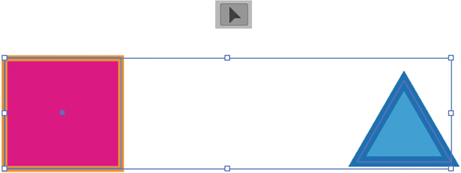
Shift+ Click to select the two shapes with the Blend tool
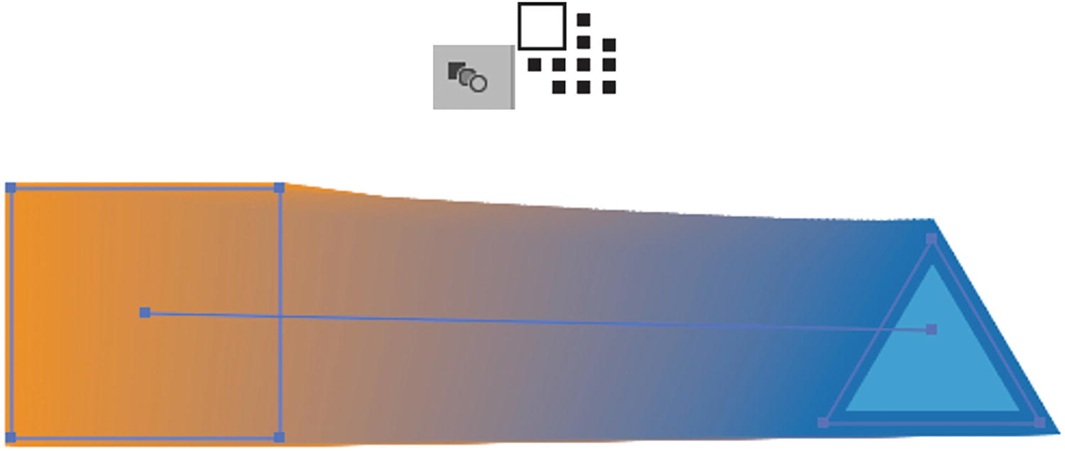
Click with the Blend tool on each shape to create a smooth blend
This created a blend based on the current blend option settings, which we will look at next. You can use the Selection tool if you need to move the blend.
If you clicked on anchor points by accident, rather than clicking on the centers of the shapes, it will cause the blend to happen from those anchor points and produce some unusual results. In this case, the pointer icon had a black square. Refer to Figure 6-5.
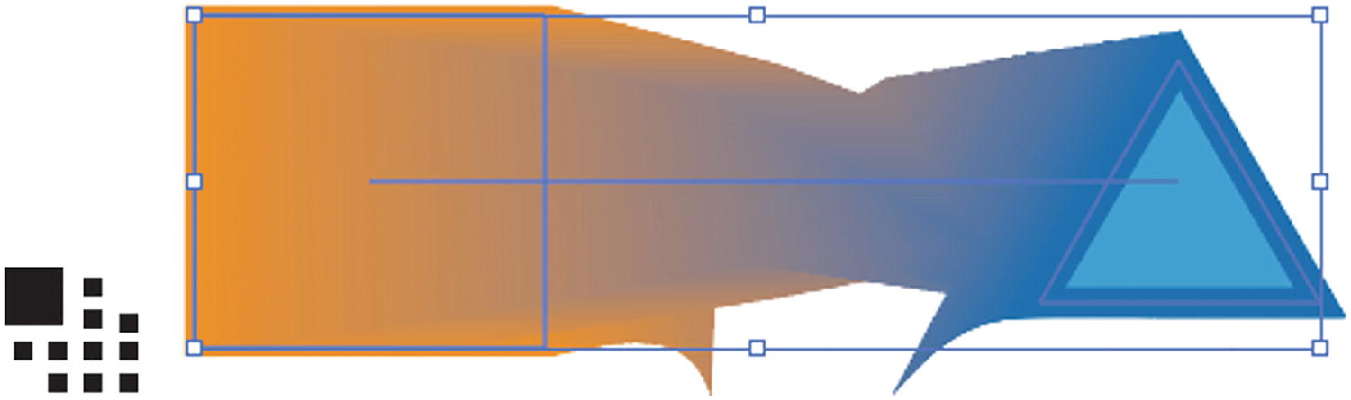
Clicking on anchor points with the Blend tool changes the tool’s pointer and alters the blend
Blend Options and Menu
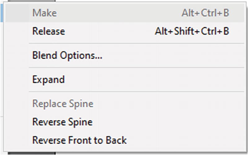
Object ➤ Blend
Make: If you have not already clicked with the Blend tool on the two selected objects, then you can use this menu option instead to create your blend.

The result of releasing a blend

Blend Options dialog box and the buttons in the Properties panel’s Quick Actions
Smooth Color: Used to create a graduated blend of color, very much like a gradient but made of many paths. It automatically calculates how many steps are required to get this effect for a smooth blend. Refer to Figure 6-9.
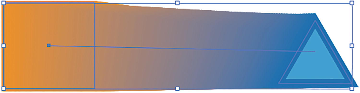
Spacing Smooth Color blend example
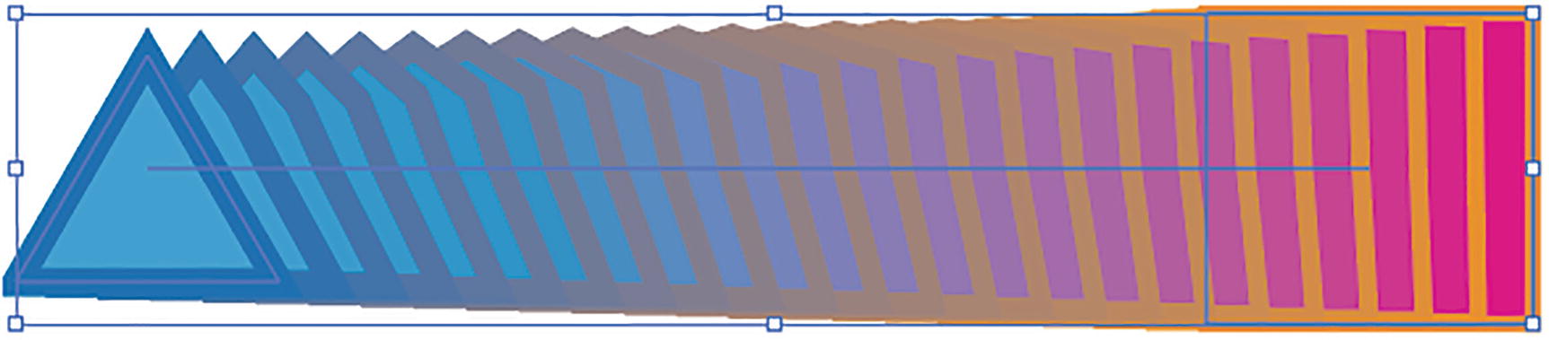
Specified Steps: This can be set to a range of 1–1000 steps and gives a similar gradation. Fewer steps are good if you want to see some spacing or viewable transition between the steps. For example, if I set the steps to 5, then we will see five transition steps between the square and the triangle in both shape stroke and color. Refer to Figure 6-10.
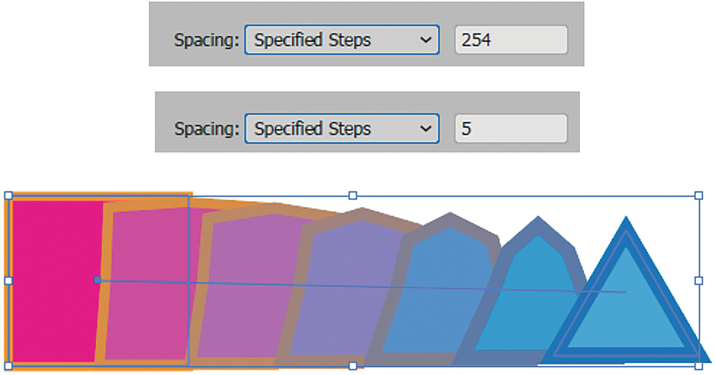
Spacing Specified Steps blend example
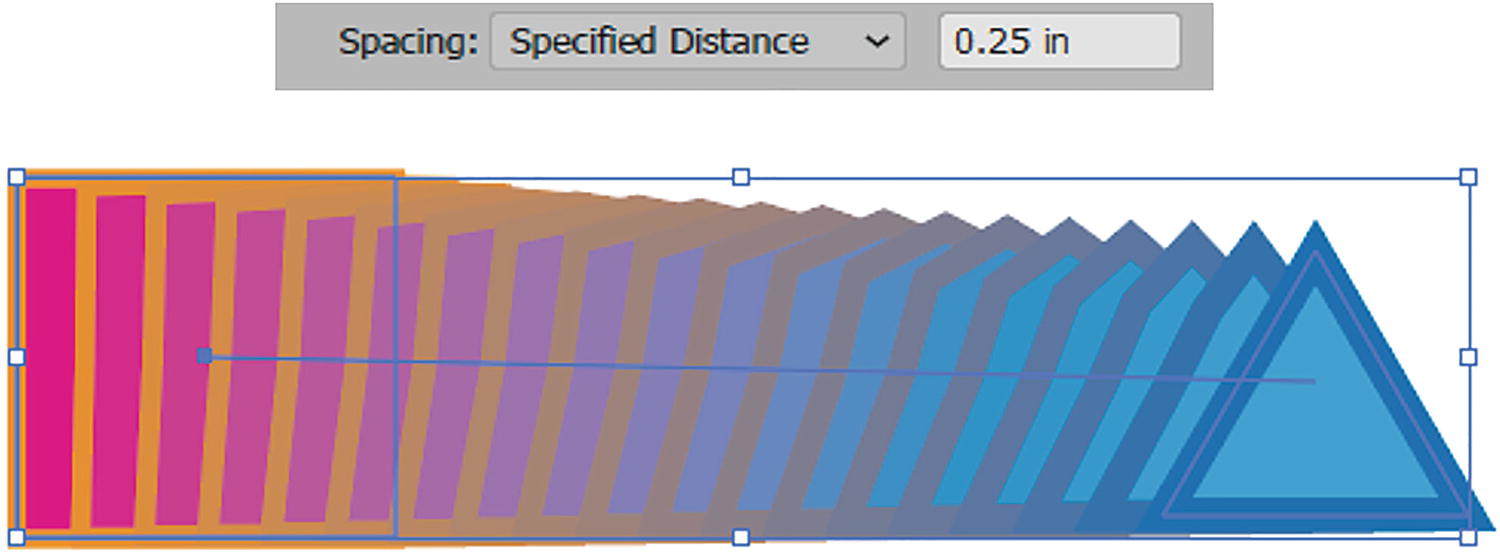
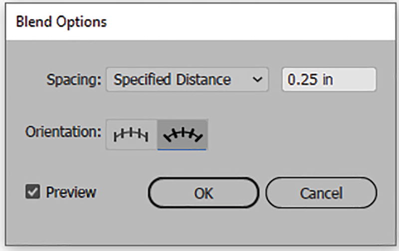
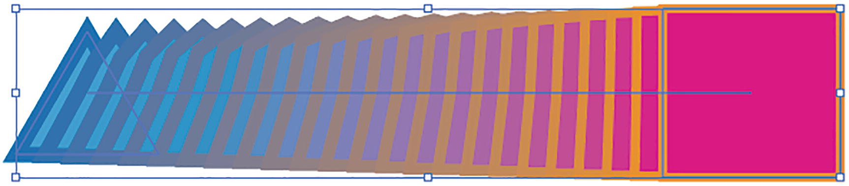
Specified Distance: This sets a distance between each of the transitions to create a distance based on units of increments, in this case inches. If I set the spacing to a higher number like 0.25 inches and click or tab outside the text box, you can see the spacing more clearly. Refer to Figure 6-11 and Figure 6-12.
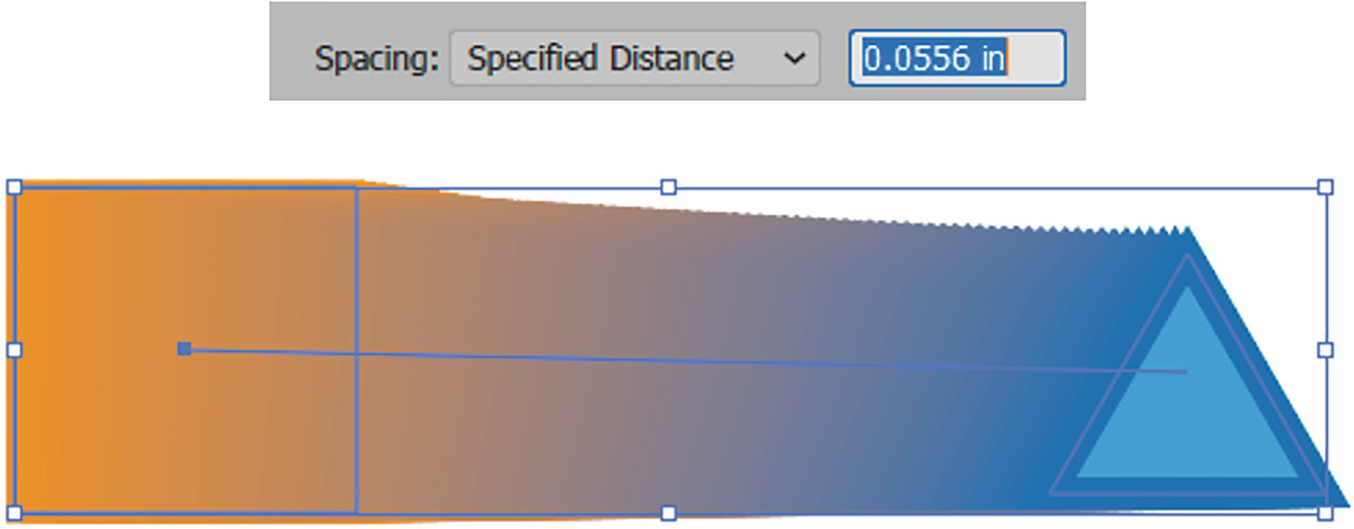
Spacing Specified Distance blend example
Distance blend example with more space
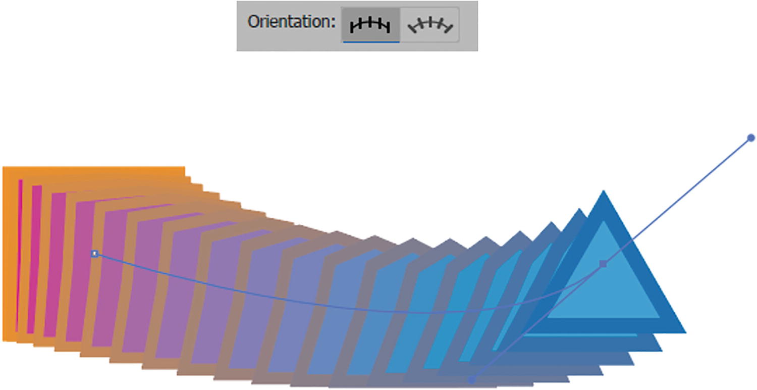
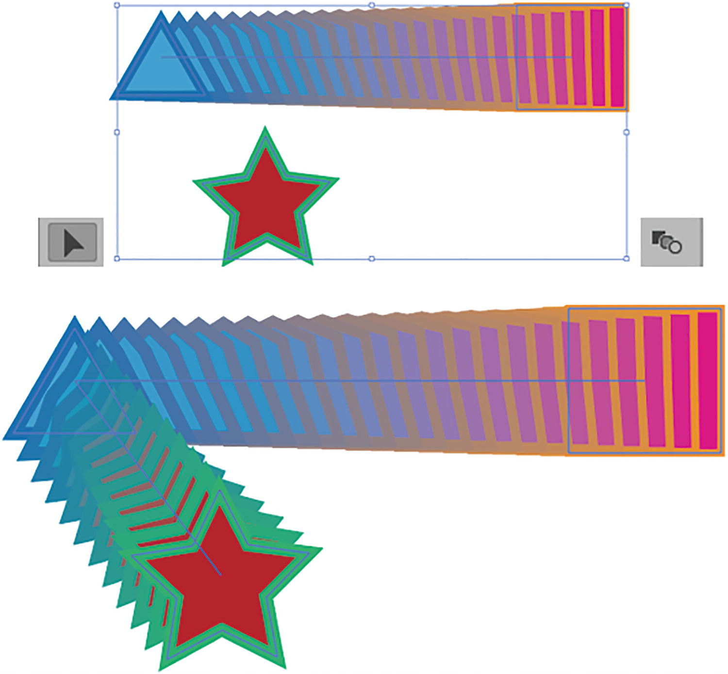
Orientation: Can be used with all three spacing settings. Currently, in these examples, the default is set to Align to Page. Refer to Figure 6-13.

Blend Options Orientation setting of Align to Page

Blend Options Orientation setting of Align to Path
Blend Options Orientation setting of Align to Page, and click OK to exit
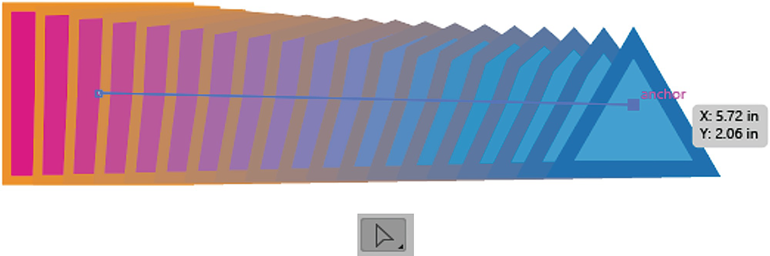
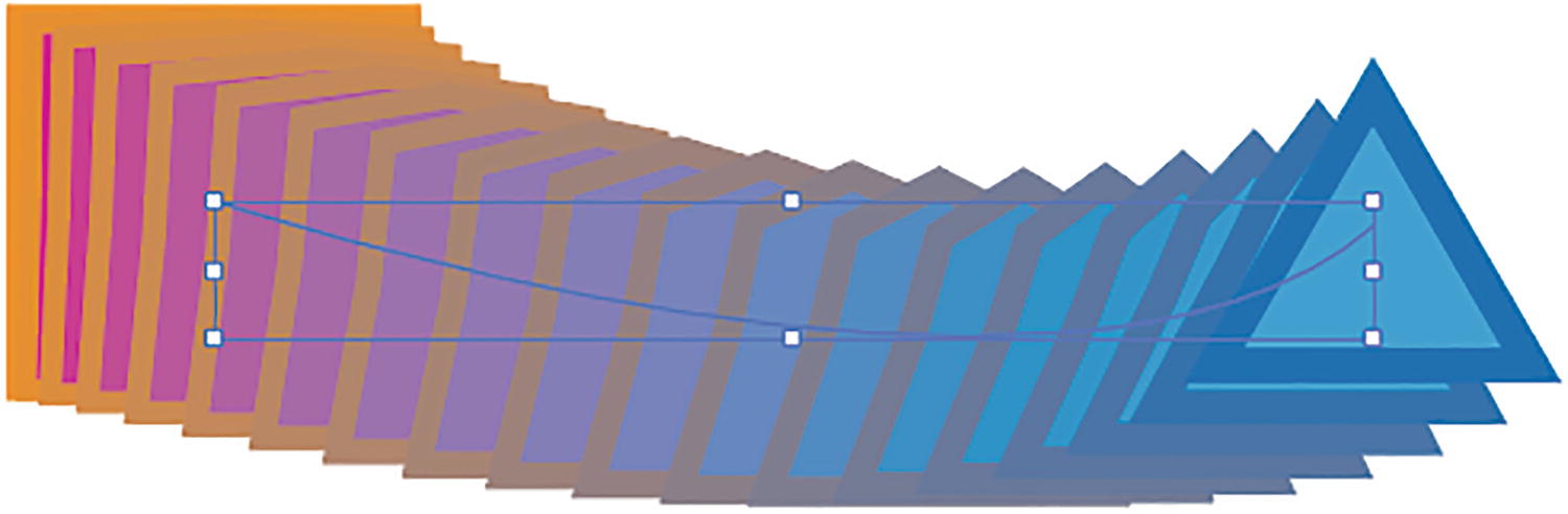
Selecting a point on the spine with the Direct Selection tool

Altering a point on the spine with the Anchor Point tool
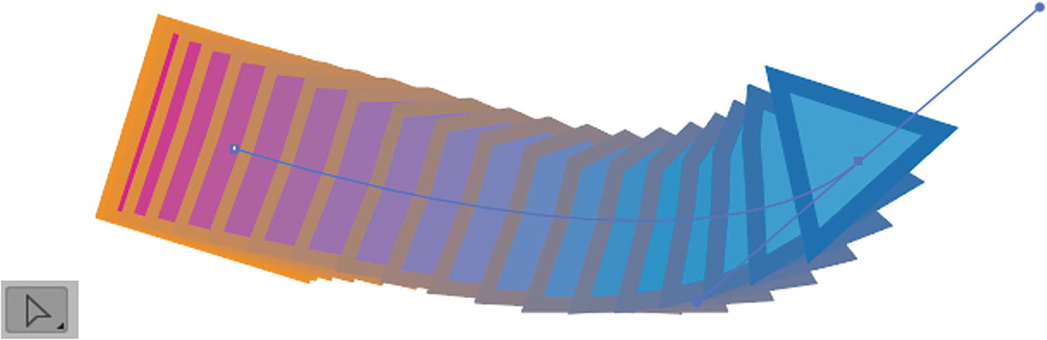
Further altering the spine with the Direct Selection tool
Setting the Blend Options orientation back to Align to Page
Click OK to exit the Blend Options dialog box to confirm the change. Refer to Figure 6-15.
Additional Options in the Object ➤ Blend Menu
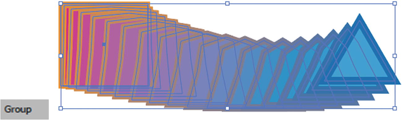
An expanded blend is now part of a grouped object
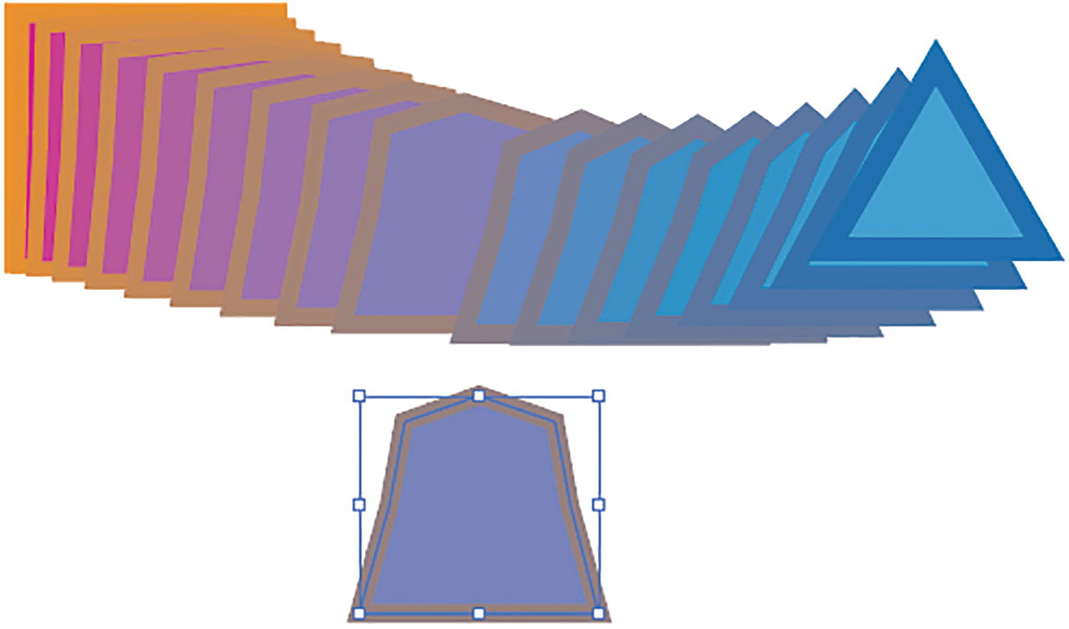
You can remove shapes from an expanded path to use for other projects
Return your shapes back to the blend state

Use the Selection tool and Object menu to replace the spine on a blend
The spine is now replaced with the new path.
Reverse Spine Blend
Reverse Front to Back blend
Adding more shapes to the blend when selected with the Selection tool and then the Blend tool
You can also add more shapes to the selected blend spine. With the Selection tool, Shift + Click on another shape, then with the Blend tool click first on one end of the blend and then on the new shape to add it to the blend and spine.
Scaling Blends

Scaling selected parts of a blend

Altering the color and opacity of selected parts of a blend
When the entire blend is selected, overall opacity can be altered using the Control panel, as well as being able to recolor artwork. Refer to Figure 6-29.

Using the Control panel to alter the overall opacity of the blend
We will explore opacity and transparency in more detail in Chapter 8.
Blending Complex Group Objects

Creating a blend between two girls
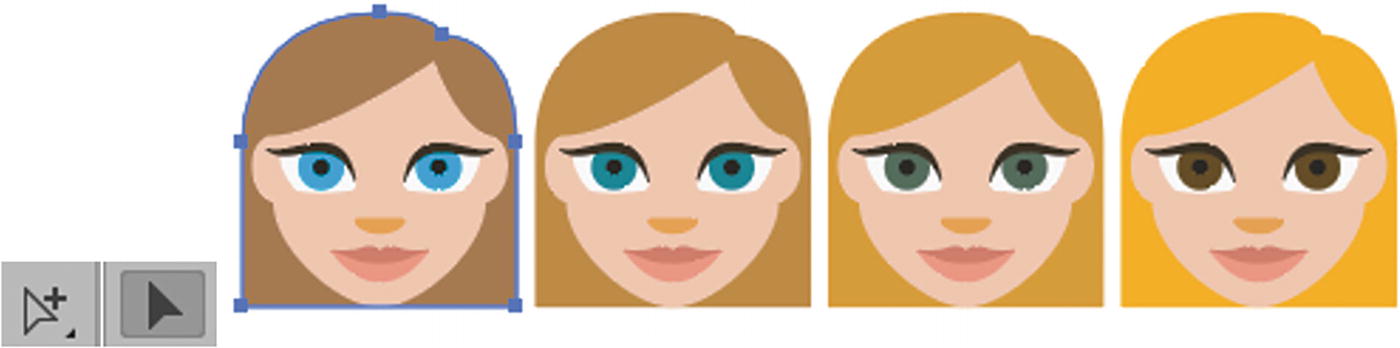
Here, we can see an example of two grouped faces of some girls, which I modified originally from the EmojiOne Color font. You can find these in my file blend_tool_examples1.ai. Save a copy if you want to edit the file.
One Girl has blue eyes and the other has brown, but otherwise they are the same in scale and shape.
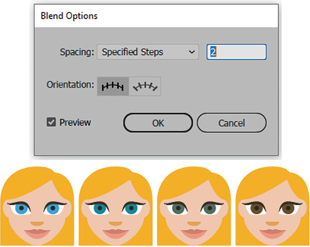
Blend options of two specified steps, and the result
Altering the girl’s hair color with the Group Selection and Selection tools updates the blend
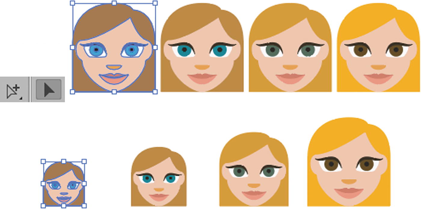
Use the Group Selection and Selection tools to scale the girl
Simple group blends like this work very well, as the similarities between the two grouped shapes are close. Illustrator must do very few calculations to create a blend.
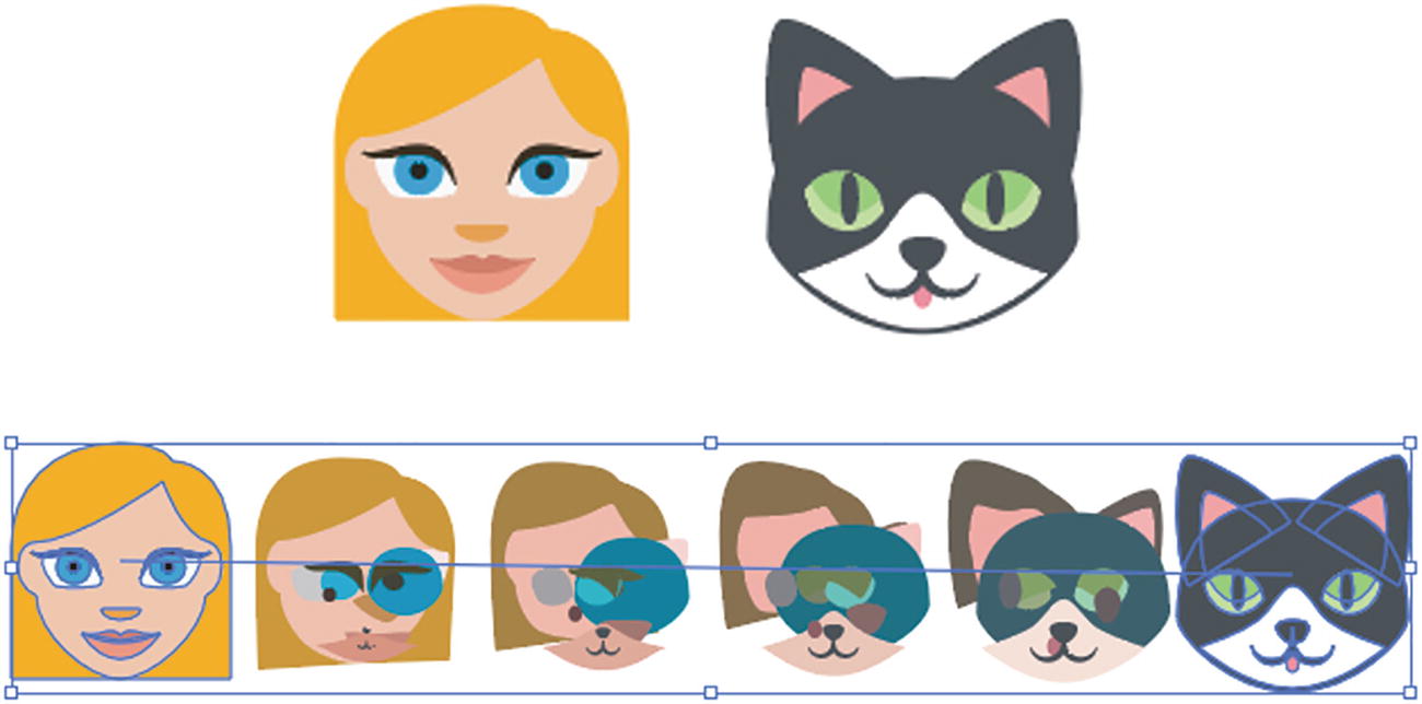
Trying to blend a cat and a girl does not always produce the best results
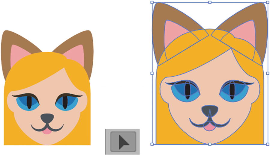
Create your own custom morph with the Selection tool and parts of two illustrations
We’ll explore this kind of complex blend issue further later in the chapter when we look at Wolf Girl and Photoshop.
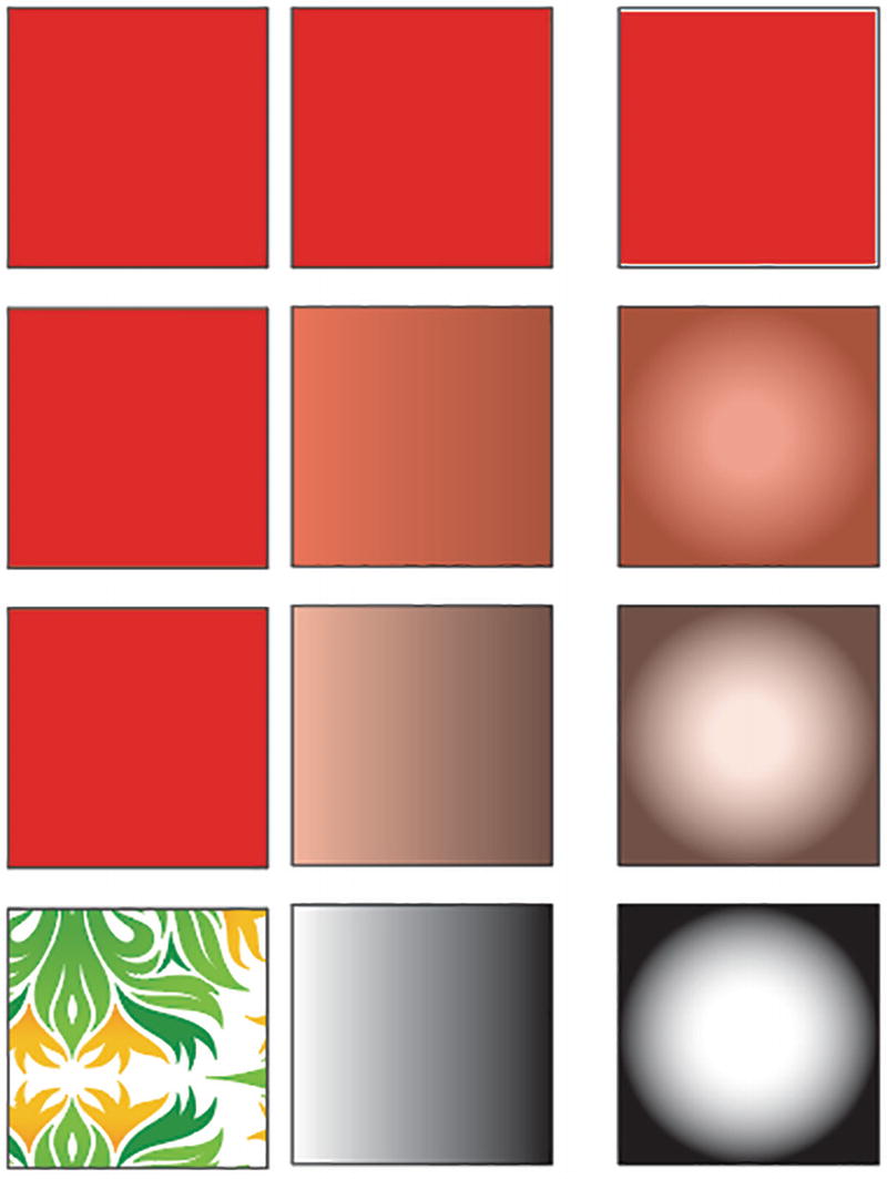
Patterns and most gradients do not blend well into solid colors using the Blend tool
In the case of patterns, no blend occurs between a solid shape and a patterned shape. However, with a simple gradient a smooth color transition can occur. But with a more complex gradient, additional blend steps are required. We will need a different set of tools if we want to blend patterns and gradients.
We’ll explore how to build and blend patterns and solid colors in Chapter 7, and multiple gradients in Chapter 8.
As mentioned, you can look at some of these examples in my file, blend_tool_examples1.ai.
Symbols and the Blend Tool
Any object that you want to repeat can be turned into a symbol
After you have created a grouped object that you might want to use multiple times throughout your document, you can store it as a symbol.
Open the file tree_blend_symbol_start.ai. Save a copy if you want to practice.
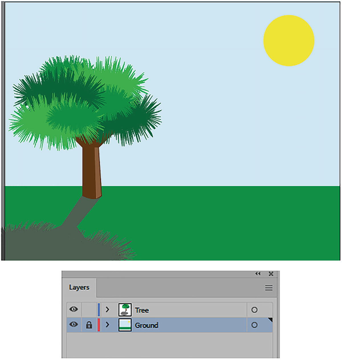
In this example, I start with a grouped object of a tree that includes a shadow on the Tree layer.
What Is a Symbol?
Grouped objects are not symbols, and each must be updated separately
A better way to globally edit objects is to turn them into symbols.
A symbol is a collection of paths or grouped objects that you can reuse in your document multiple times, which reduces file size. These files are linked to the Symbols panel.
A symbol is similar to a Photoshop Smart Object in that it can act as a template without destroying the original while you do basic scaling and rotation.
Symbols Panel
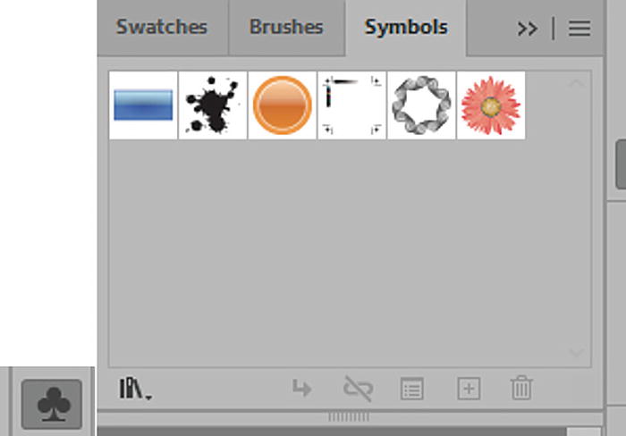
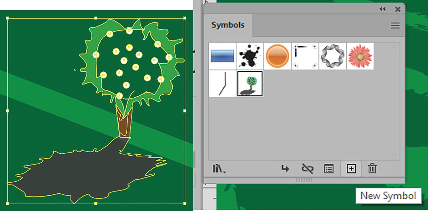
Symbols panel for storing symbols in your document

Select a grouped object and add it to the Symbols panel
Symbol Options
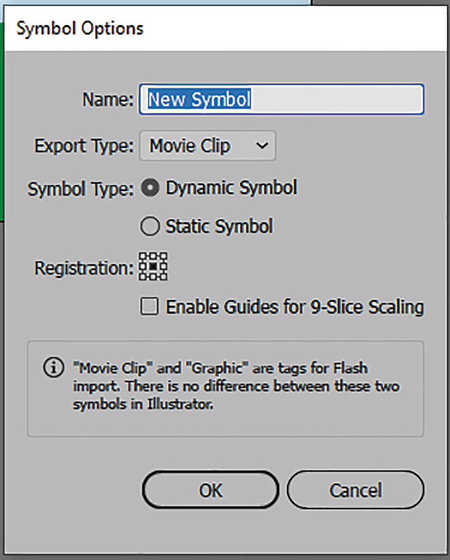
In the options, you can rename the symbol to “Trees.”
Export Type: Either Movie Clip or Graphic. However, in Illustrator this makes no difference, as this is specifically if you use the symbol in an application like Adobe Animate (formerly Flash). So, in this case, I leave it at the Movie Clip setting. Refer to Figure 6-42.

Symbol Options dialog box; Export Type options are only relevant to the Animate application
Symbol Type: Symbols come in two kinds, either dynamic or static. Refer to Figure 6-43.

Symbol Options dialog box; Symbol Type options
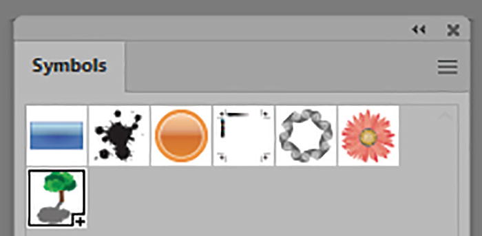
Static and dynamic symbol examples in the Symbols panel
Static Symbols: Like a grouped object, they allow you to move, scale, rotate, reflect, and shear. However, you can do that to the instance of the symbol on the Artboard without affecting the original file stored in the panel. However, the colors of the symbol’s fill and stroke are locked and cannot be edited, unless you use the Control panel to edit the original “master” or parent symbol, which we will look at in the next section. Refer to Figure 6-45.

You can move, scale, and rotate a static symbol
You cannot alter or distort the perspective of a symbol using the Free Transform tool mentioned in Chapter 3 with the Perspective and Free Distort options, as this would alter the structure. In this case, when attempted, the action is canceled and the symbol remains undistorted.
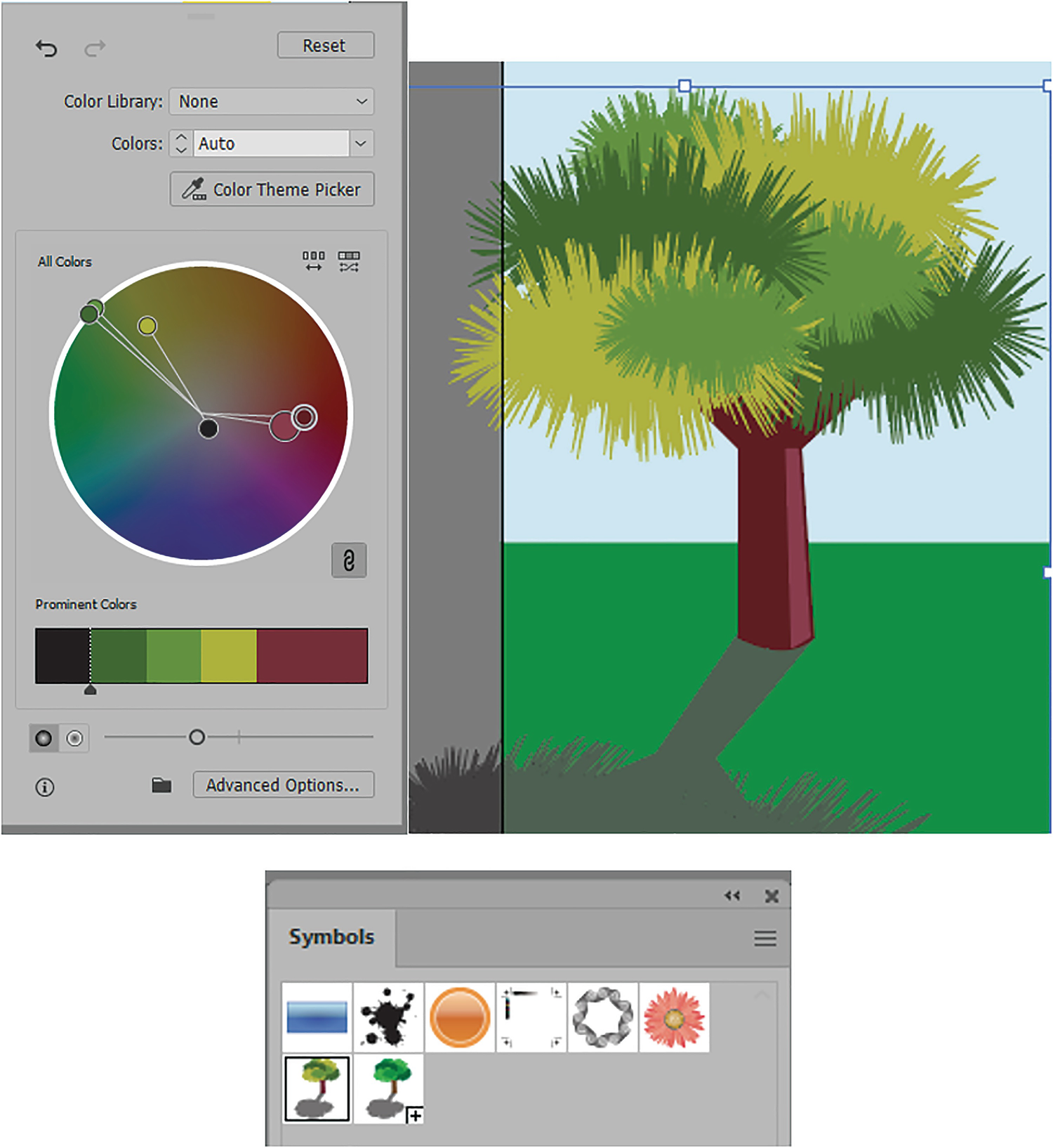
Dynamic Symbols: These allow you to do the same scaling and moving as a static symbol. However, you can also edit the individual colors on the symbol on the Artboard, using the Direct Selection tool. You can use the Toolbars and Swatches panels to select and swap solid colors, gradients, and patterns in the fills and strokes if the path in the symbol already has a stroke. Refer to Figure 6-46.
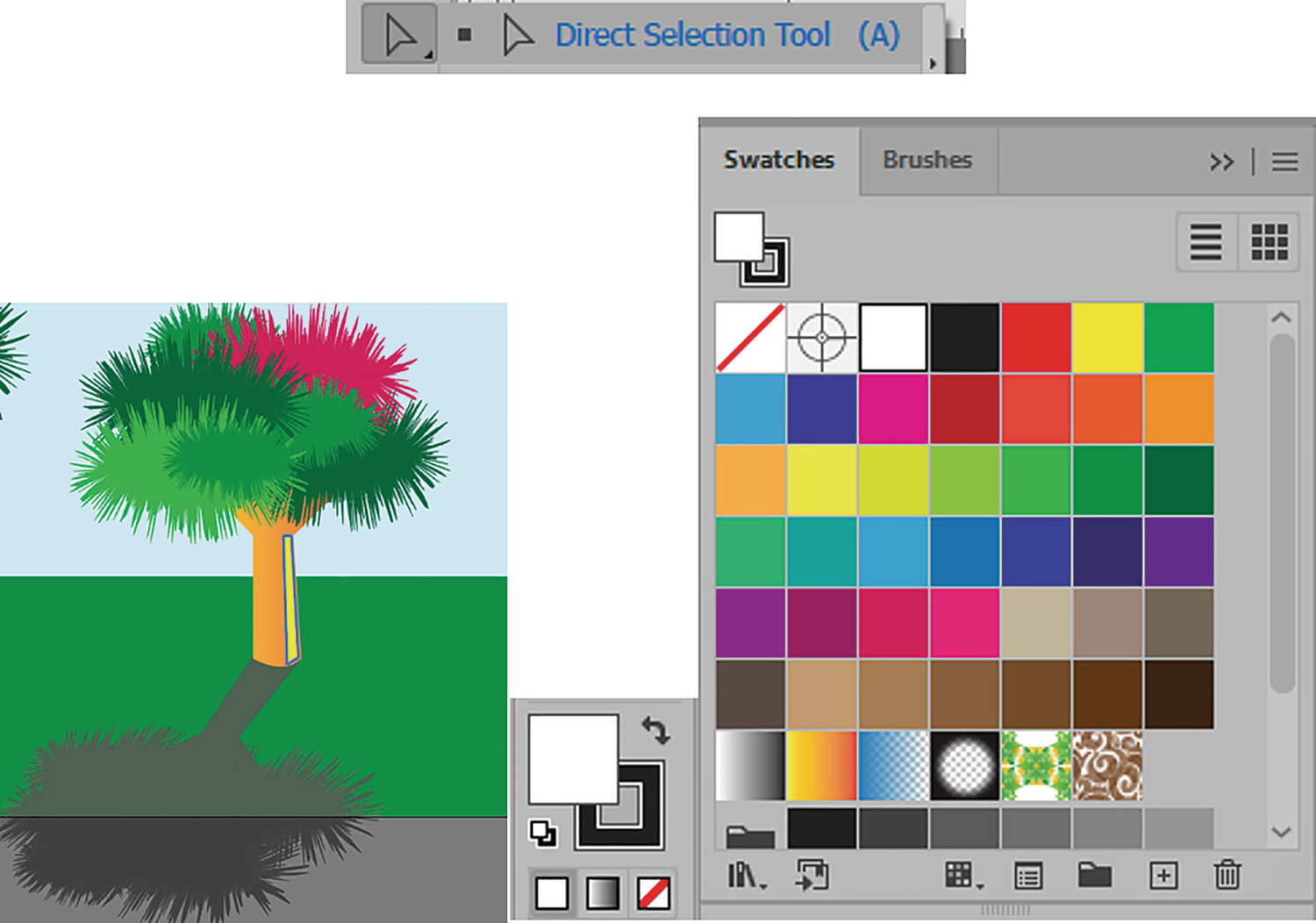
Dynamic symbols allow you to alter color of selected paths using the Direct Selection tool and can be colored with your Toolbars or Swatches panels

The dynamic symbol in the Symbols panel is not altered by the color change
Symbols, whether static or dynamic, can also have additional live effects from the Effects menu applied. We will look at that in more detail in Chapter 11.

Symbols in this chapter are set to be static symbols
You can also set the registration or reference point for the symbol. In this case, I leave it at the center.
Enable Guides for 9-Slice Scaling refers to when working in Animate with graphic or movie clip symbols; it does not apply to this book. However, if you need more details on that topic or symbols in general, you can refer to the following link: https://helpx.adobe.com/illustrator/using/symbols.html. See “Use 9-slice Scaling.” Refer to Figure 6-49.

Symbol Options dialog box for setting Registration and Enable Guides for 9-Slice Scaling

The symbol is added to the Symbols panel

Place Symbol Instance icon

Break Link to Symbol icon

Symbol Options icon
New Symbol icon can also duplicate a symbol
Be deleted by clicking on the Delete (trash can) icon. Click Yes or No to any message to delete. However, if a symbol is already on the Artboard, you may get the following warning message. And you must choose whether to Expand Instance (Unlink), Delete Instances on the Artboard, or Cancel the Delete. Refer to Figure 6-50 and Figure 6-55.
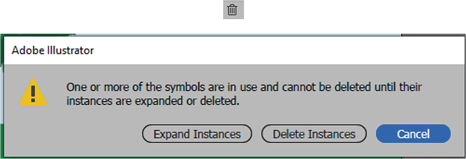
Delete icon also triggers a warning message if symbols are on the Artboard
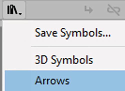
Libraries icon in the Symbols panel

Enter Symbol Editing mode when you double-click on a symbol
If upon entering your symbol you find that any of your object paths are ungrouped you can enter the symbol and Object ➤ Group the selected paths so that when you break the symbol it does not become ungrouped.
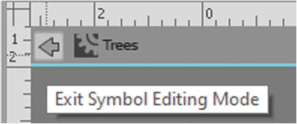
Exit Symbol Editing mode
Symbols Control Panel

Static symbol options in the Control panel
For both static and dynamic symbols, you can edit the following:

A symbol can be either a move clip or graphic

Control panel options for static symbol
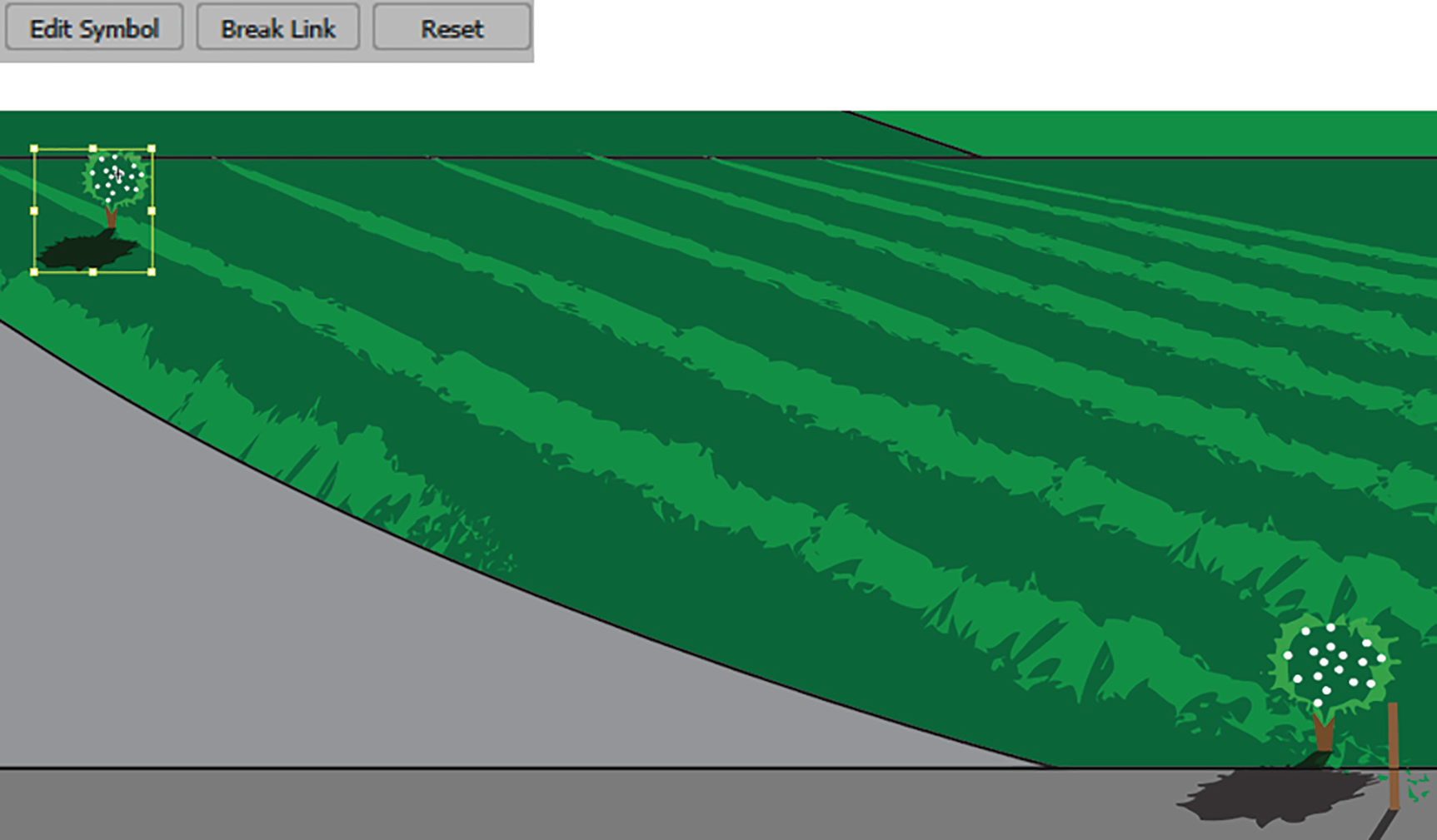
You can also enter Symbol Editing mode by clicking on the Edit Symbol button.
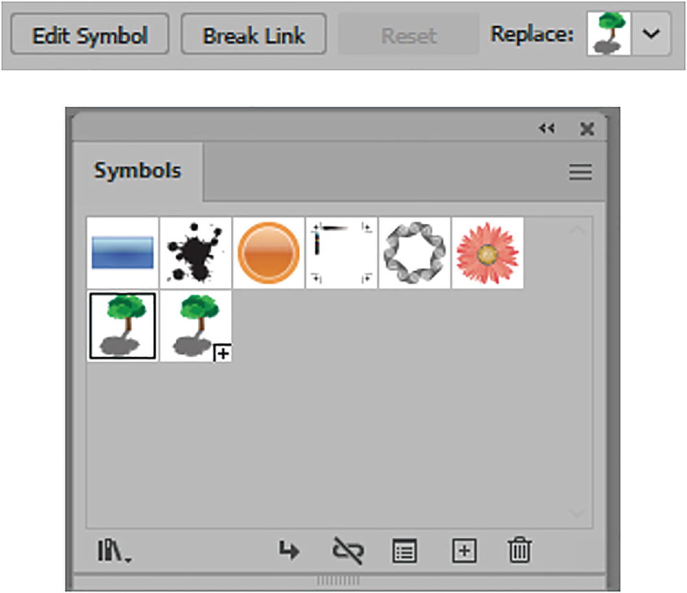
Edit your symbol or break the link with your symbol using the Control panel or Symbols panel

Reset the symbols to their original size using the Control panel

Replace the symbol using the Control panel
In the Symbols panel menu is another option called Redefine Symbol. This can be used after you have broken the link with a symbol. Make some edits to the object, and then, with the group selected, choose Redefine Symbol from the menu. Refer to Figure 6-65.

Break link to a symbol and redefine it using the Symbols menu
The previous selected parent symbol is then updated with the changes without entering Symbol Editing mode.
Returning to the Control Panel Options

Alter the opacity of a symbol
Recolor your parent symbol using the Control panel

Use the Control panel to align two or more symbols

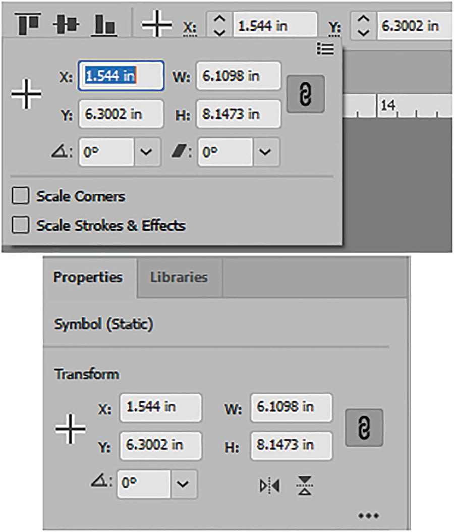
Use the Control panel to set the X and Y coordinates and width and height for your symbol
As with paths, shapes, and other grouped objects, you can set the symbol’s X and Y coordinate values, as well as its width and height. You can constrain width and height proportions with the Link icon. All the numbers are based on the registration point. Refer to Figure 6-69.
Use the Control panel to perform basic transforms on a symbol
Additional options include rotate, shear, flip horizontally, or flip vertically.
You can also switch back to the normal reference point if you uncheck Use Registration Point for Symbol in the Transform menu. Refer to Figure 6-71.
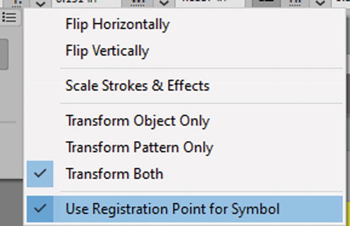
You can set the reference or registration point using the Transform menu

Symbols can be saved as an .ai file
We will look more at editing and working with symbols and their related tools in Chapters 11, 12, and 13.
Apply the Blending Tool to the Symbol
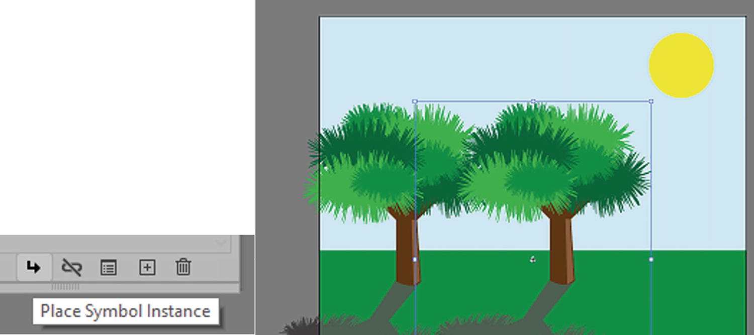
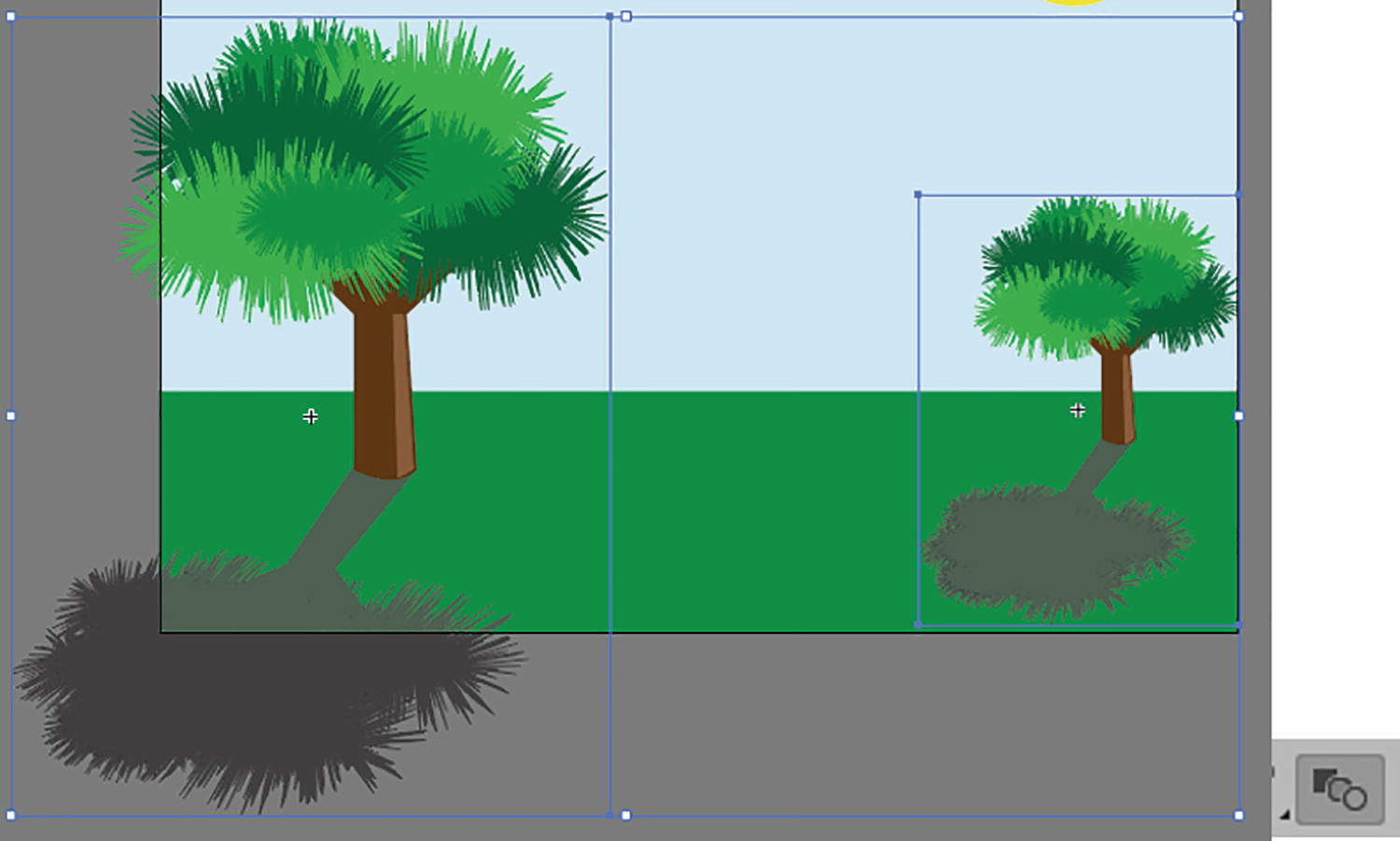
Place an additional symbol on the Artboard using the Symbols panel

Scaling one of the symbols with the Selection tool
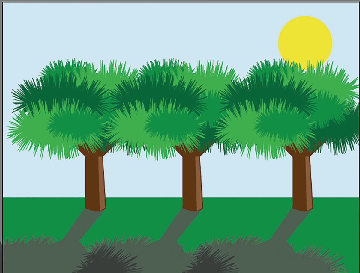
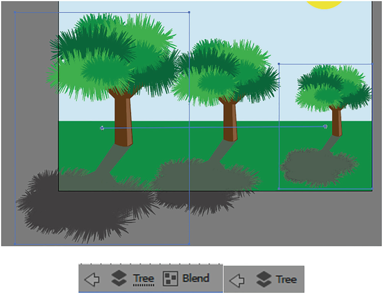
Click on both selected symbols with the Blend tool
Enter Symbol editing mode when you need to make a global edit to the blend
With this knowledge, we can now start to plant the bushes on the farm in the next project. Save your work on this file, and you can view my example in tree_blend_symbol_final.ai.
Use the blend option Spacing of Specified Distance if you need to create a more graduated blend between two symbols, as the other options—Smooth Color and Specified Steps—will create a space between each transition. Refer to Figure 6-77.
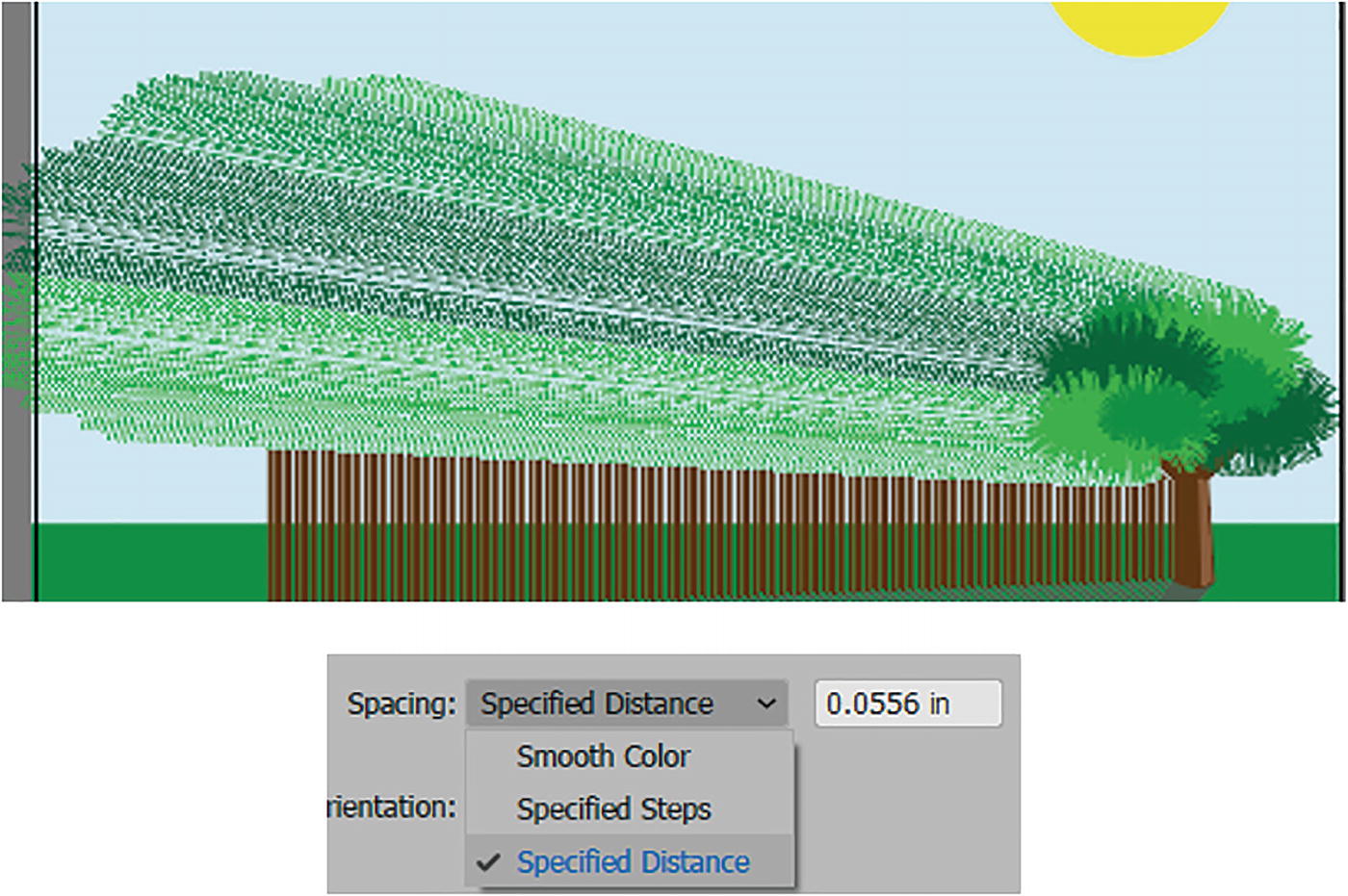
You can create some unusual effects depending on your blend option settings in the dialog box
While not relevant to this book, for your own independent projects, if you are planning on creating a frame-by-frame GIF animation in Photoshop, you might want to refer to the books I mentioned in the introduction. However, as an alternative idea, you can use the Blend tool to create your transitions and then later expand the path. These selected objects can later be added as Smart Object layers to Photoshop to create an animation. For more information on the Blend tool, visit https://helpx.adobe.com/illustrator/using/blending-objects.html.
Project: Blowing in the Wind, Part 4
To continue the project of the girl at the farm, it’s time to plant the bushes and add posts to the end of the rows.
Open Landscape1_4_start.ai and save a copy if you want to follow along for practice.
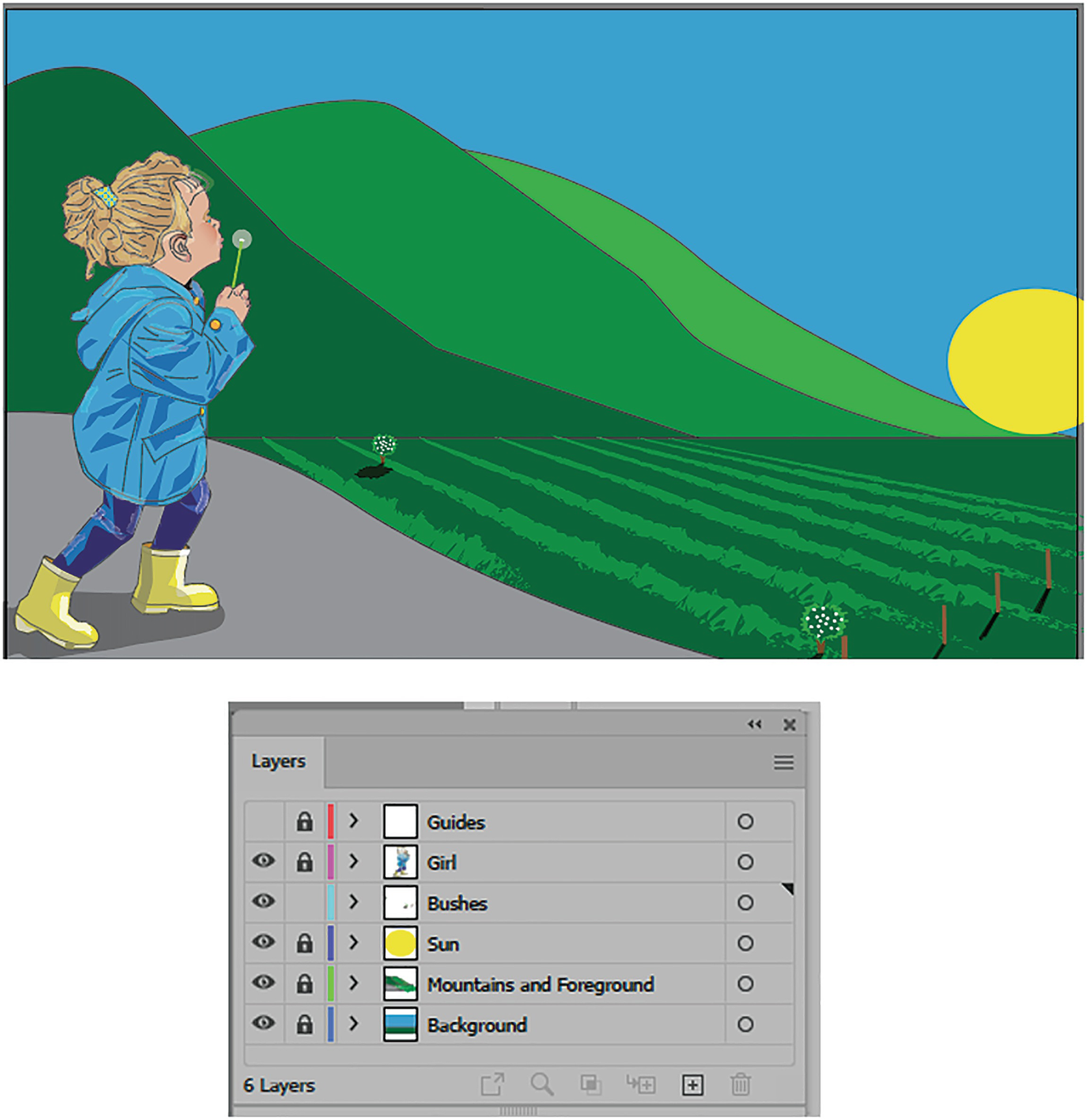
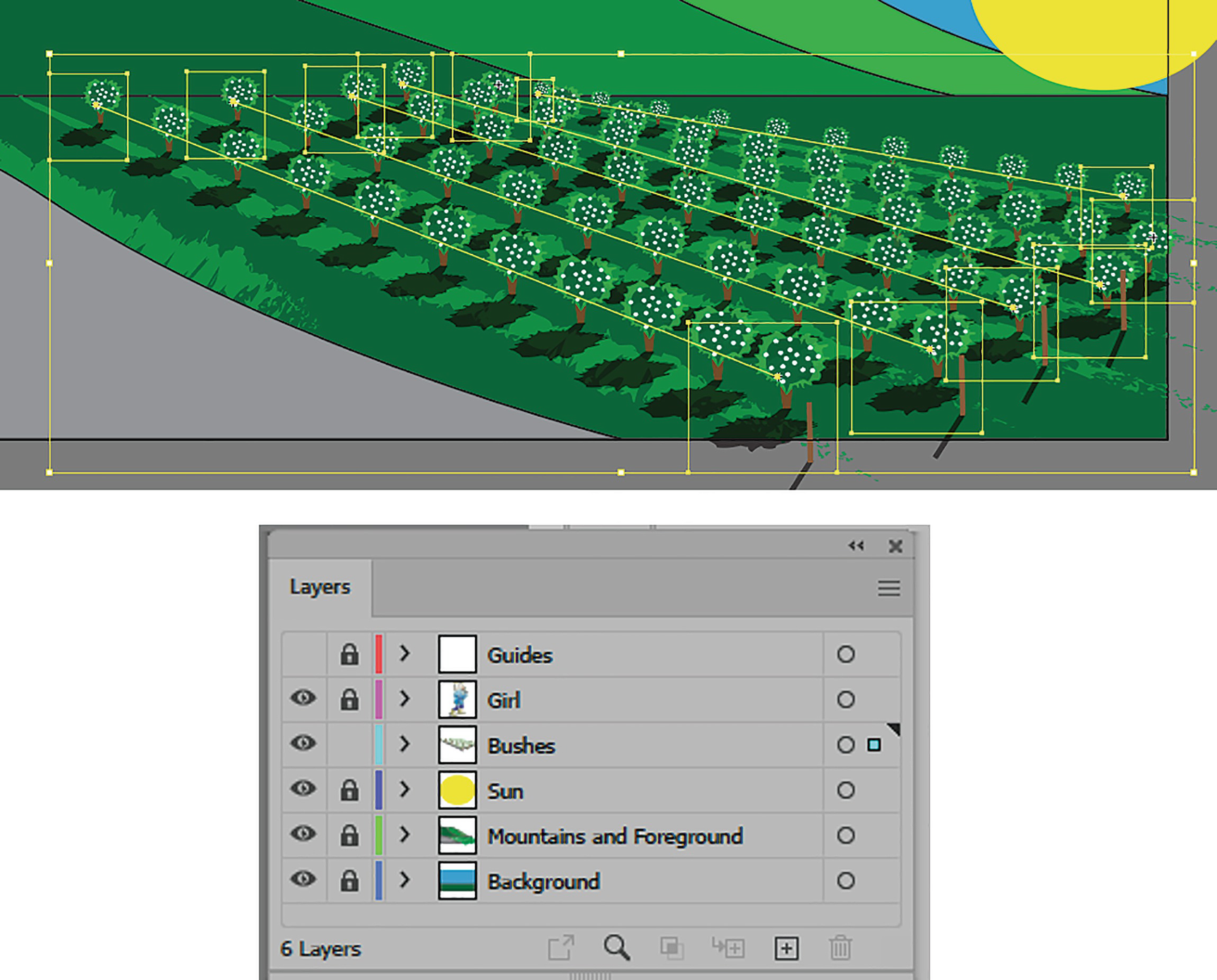
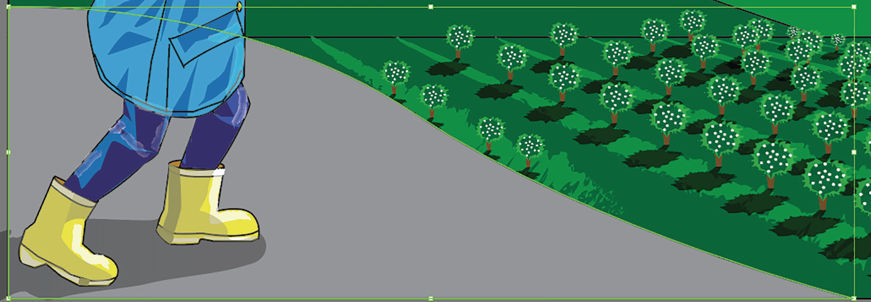
Illustration with girl on the farm with bushes ready to be planted on the bushes layer
Make sure to zoom in with your Zoom tool and use your Hand tool (spacebar) if you need to navigate around on the Artboard. Refer to Figure 6-79.

Use the Zoom and Hand tools to navigate about the Artboard
Adding Posts and Bushes as Symbols
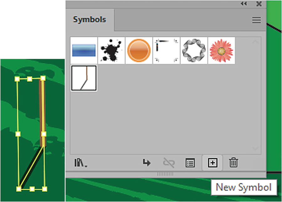
Create a new symbol
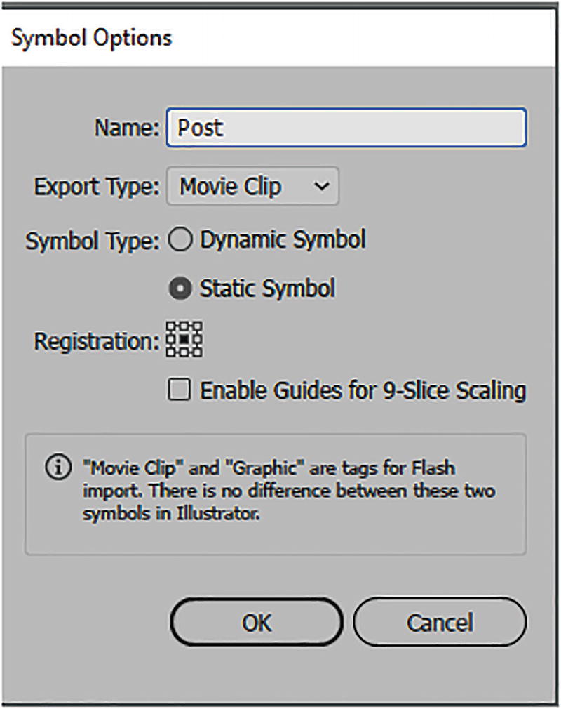
Symbol options for the Post symbol

Using the Selection tool to move the posts
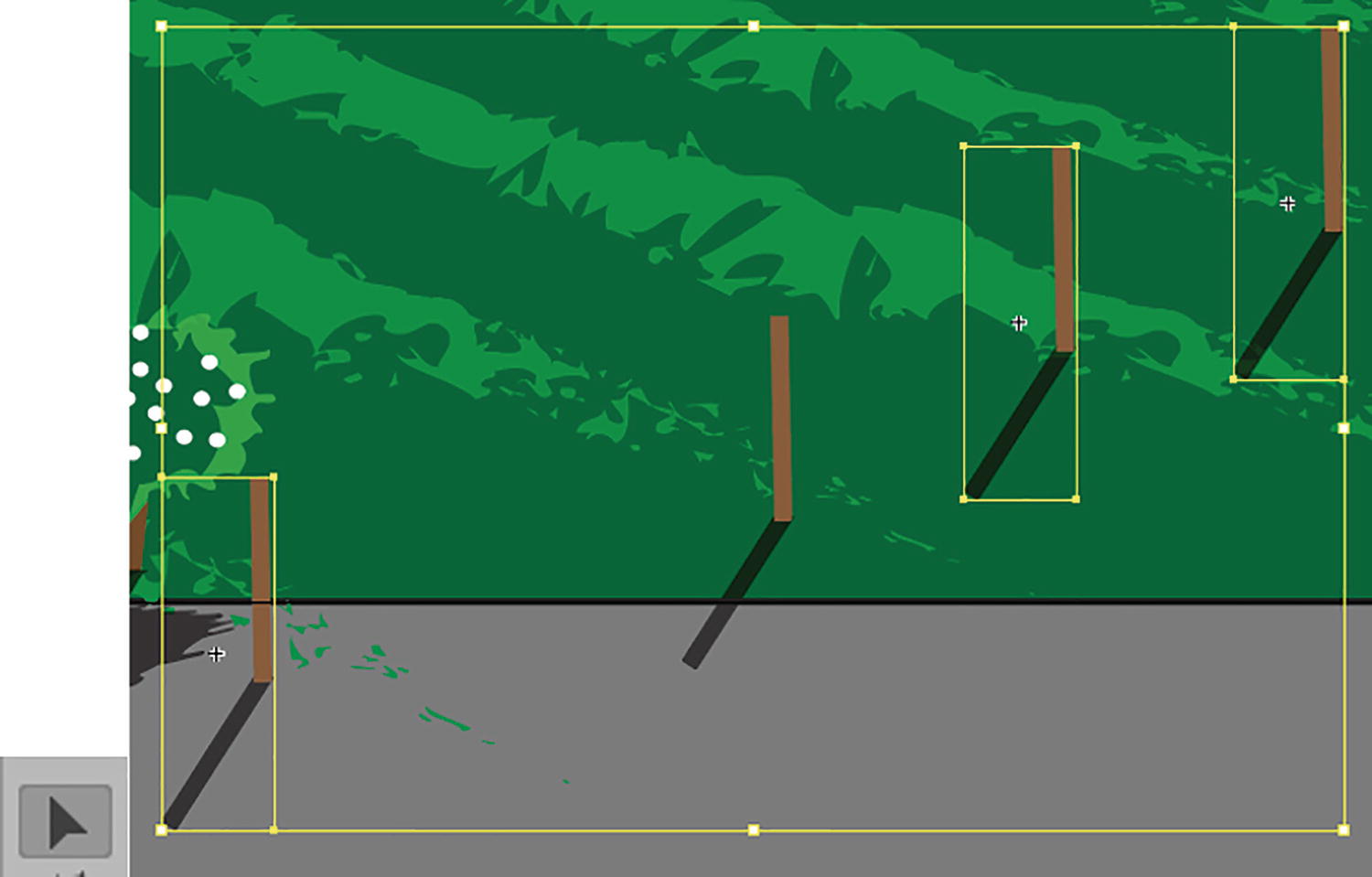
Select the three post symbols to break link from the parent symbol
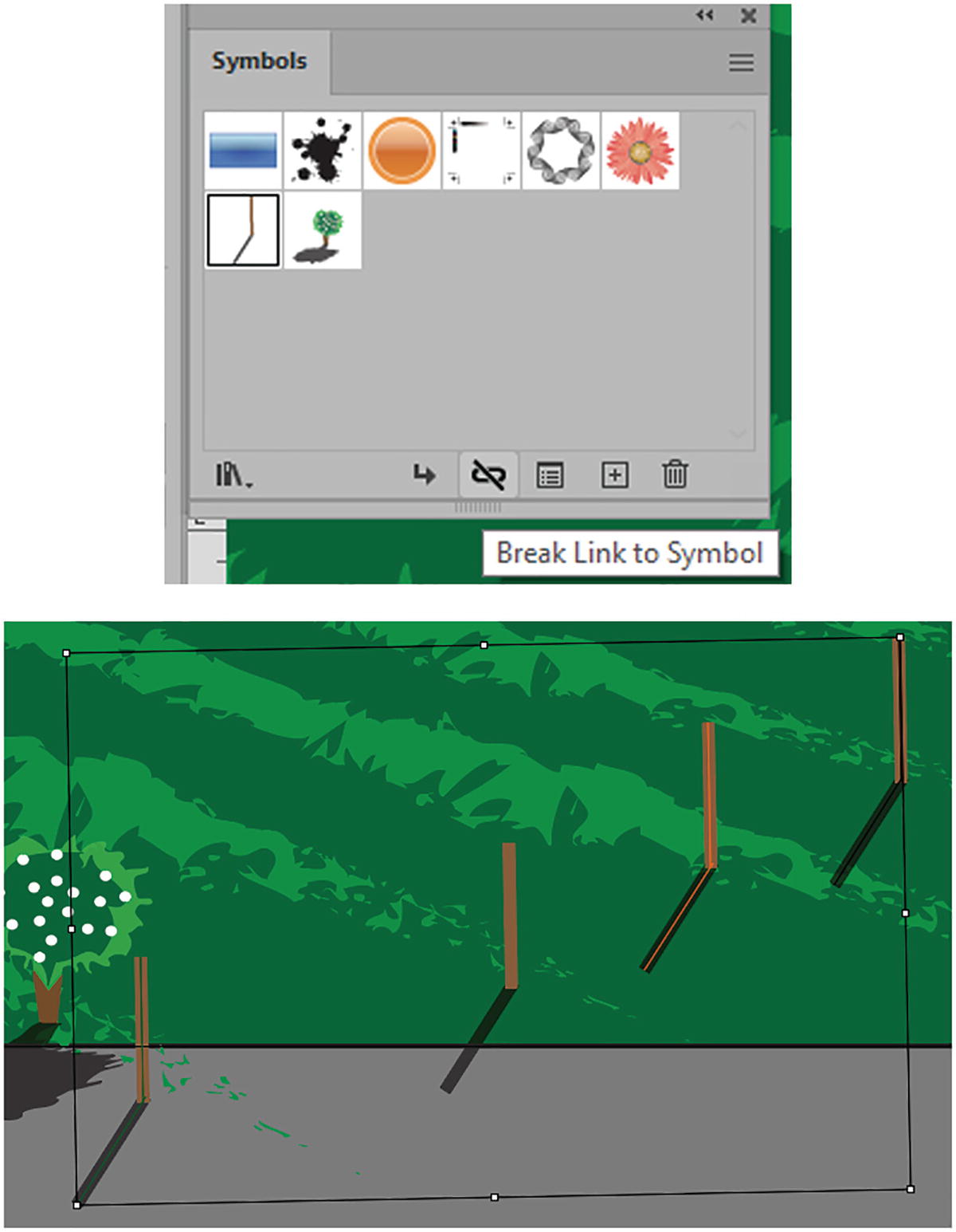
Break link to the posts using the Symbols panel

Use the Direct Selection tool to select the end point of a post shadow and move it to adjust the shadow

Group any posts that may have become detached from their shadows when broken from the symbol
As mentioned earlier in the chapter, even though the posts were grouped before becoming a symbol, they can automatically become ungrouped within the symbol, and this is apparent when the link is broken. However, to prevent this in your own projects, enter the symbol (double-click) and select all shapes and Object ➤ Group them, then exit the Symbol Editing mode. This time, when the symbol is broken it will break, but as a group and not as separate paths.
That’s OK in this example as there are only four posts and they are not difficult to update; breaking them from the symbol is not an issue. However, when it comes to the bushes, we do not want to spend a lot of time updating each one, so using symbols for them is a better option.
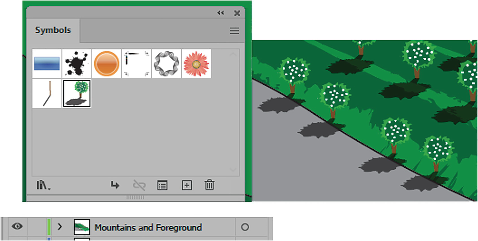
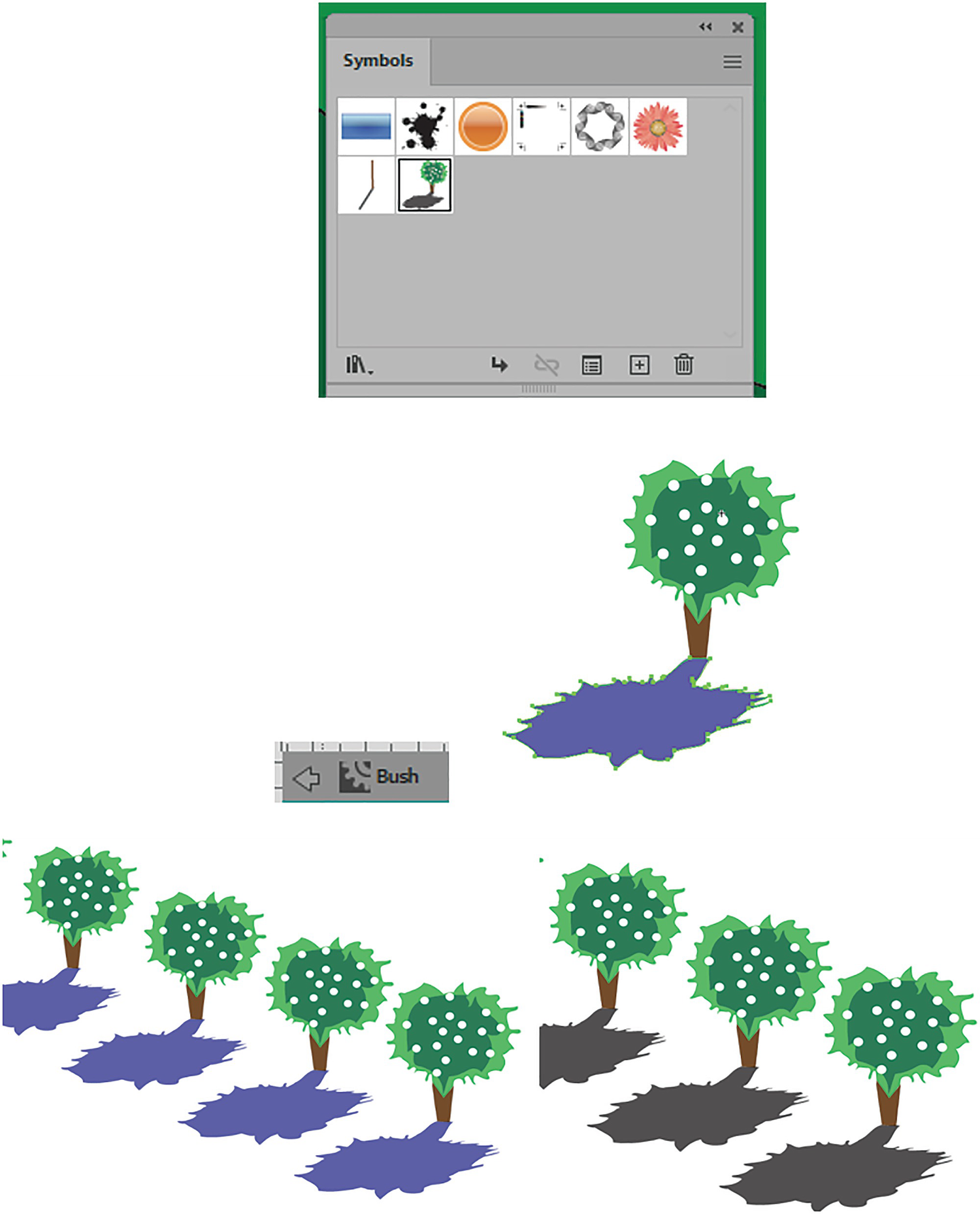
The grouped object of bush is added to the Symbols panel
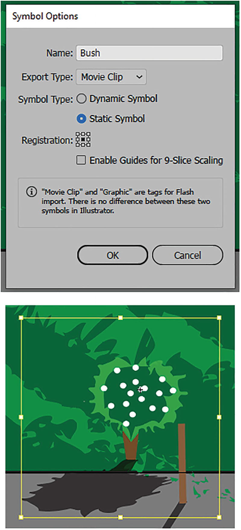
Symbol Options dialog box for the bush symbol, and the scaled bush on the Artboard near a post
Then, using the Selection tool bounding box handles and the Shift key, I scaled the bush, making it a bit larger so that it appears closer to the viewer. Refer to Figure 6-88.
Use the Control panel to reset the bush in the distance to make it smaller
Start creating the row of the bushes
Creating the Row with the Blend Tool

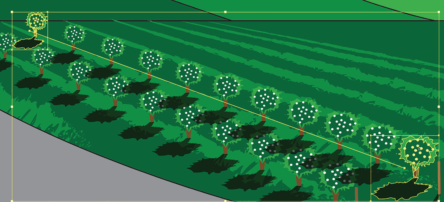
Use the Selection tool and Blend tool to create your row of bushes
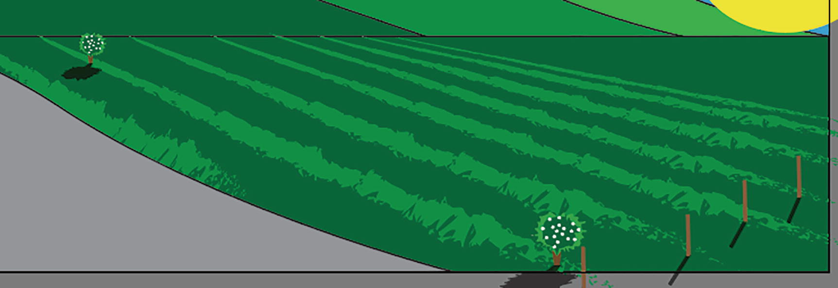
This creates a row of bushes that gradually get larger as they get closer.
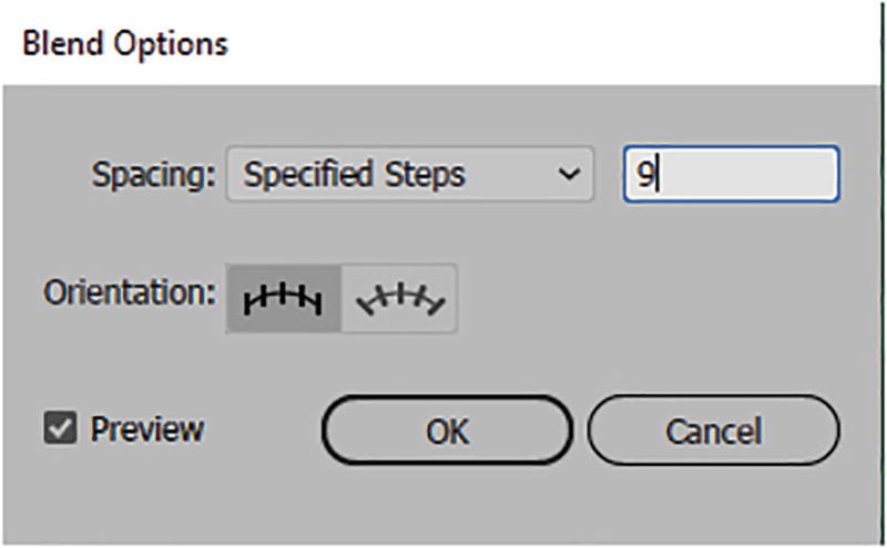
Set the Blend Options Specified Steps field to 9 for more bushes in the row
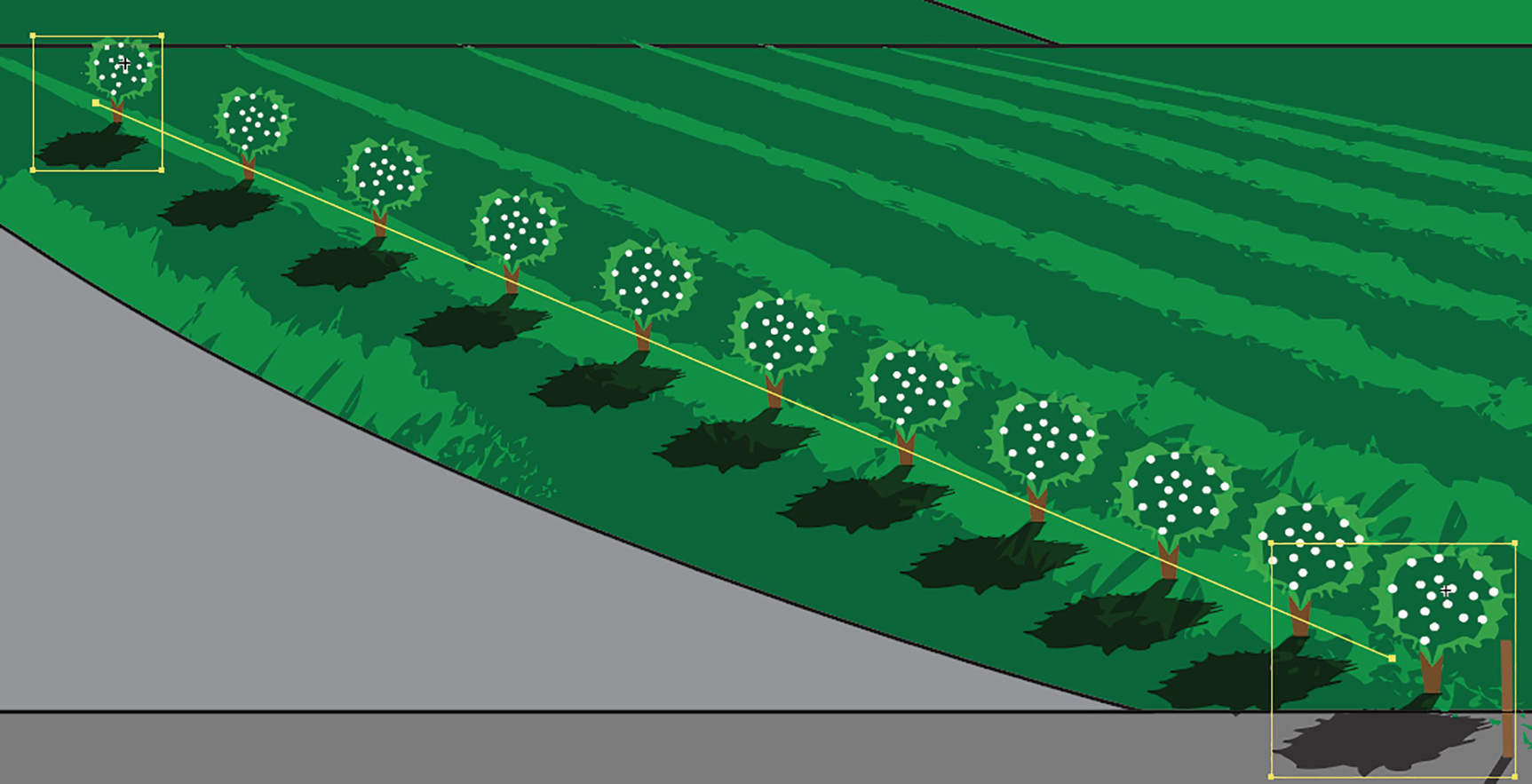
Now the row has more bushes
For your own projects, if you want to adjust the spacing afterward, you could always Choose Object ➤ Blend ➤ Expand to release the symbols from the blend but keep them grouped. Then, manually adjust the spacing using the Direct Selection tool and the Selection tool. However, I will leave them as is so that I can create more blends of bushes for my rows and adjust the spacing and scaling at the same time as required. Refer to Figure 6-94. Blends that consist of two different transitioning symbols will create grouped objects between the two symbols if they are expanded.

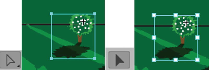
An expanded blend produces a row of symbols at various scale sizes. Use your Direct Selection tool and then Selection tool to select a symbol
Use Edit ➤ Undo if you expanded the blend by mistake, and then keep the blend spine active.
Adding More Blend Rows
Now that you know how to create one row, you can create more rows. I did that in my example Landscape1_4_final.ai, which you can refer to later.

Duplicate the selected blend rows
However, the bushes farthest away are too high on the horizon.
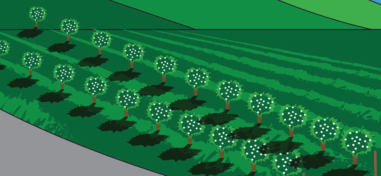
If your rows are uneven you may need to move the bushes on one end
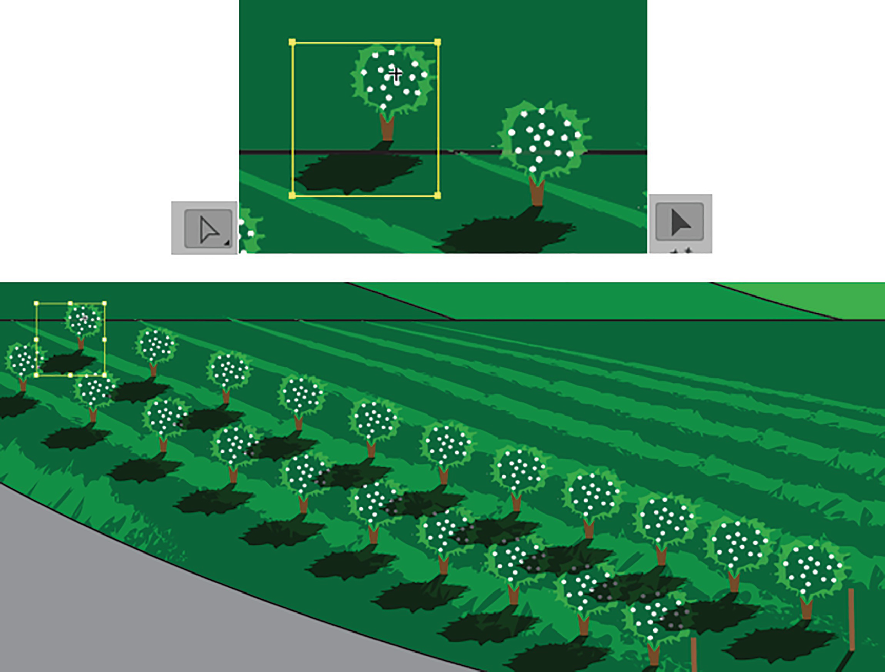
Use the Direct Selection tool and Selection tool to move your bush and adjust the blend
This causes all the other bushes in the blend to move along with it and adjust.
Select your bushes so that the shadow does not overlap the closer bushes

The new row of bushes is now behind the other
As you move your rows farther away from you, make sure to scale the symbols so the bushes get gradually smaller. However, it OK if some are slightly higher as it is a slightly hilly field, and the ground is uneven. Select a single bush on one end with the Direct Selection tool, and then with the Selection tool you can use the bounding box handles to scale the bushes as required.
You can see my example, Landscape1_4_final.ai.
On your Bushes layer, you need a total of six rows of bushes
Make sure as you add the blended rows moving away from you, that you Object ➤ Arrange ➤ Send to Back each one. That way, the bushes and their shadows will be behind the posts as well.
You can still move the bushes and scale them using the Direct Selection and Selection tools
Next, with your Selection tool, scale using the bounding box handles. Refer to Figure 6-101.
Add Additional Bushes on Another Layer
Drag out additional bushes for the closest row
Bring the foreground in front of the bushes to cover the shadow
You could scale these bushes if you wanted to, or leave them small, as not all the bushes would be planted at the same time.
Editing All Symbol Instances
Remember: Now that the bushes are all the same symbol, you could double-click on the symbol in the Symbols panel and make alterations, such as to a color on a selected path. Use the Control panel in Symbol Editing mode and then exit, using the arrow below the rulers, and all the bushes will update at the same time.
Enter the symbols by double-clicking on them in the Symbols panel, and exit Symbol Editing mode to see the result
Use Edit ➤ Undo a few times or use the History panel if you need to undo those steps, but don’t delete the symbol in the process. If that happens, then use Edit ➤ Redo or Shift + Ctrl/CMD+Z, or find the correct state in the History panel.
See the earlier note about what to do if you need to group your paths while in Symbol Editing mode before breaking symbols for your own projects.
Then, lock your layers in the Layers panel.
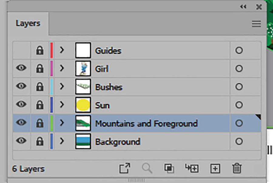
Lock your layer in the Layers panel
In the next chapter, we will start adjusting the foreground so that it has a bit more texture.
Project: Wolf-Girl
Open the file wolf_girl_blend.ai. We are just looking at this file and another one as part of the discussion on what to do when you have complex blends.
Complex illustrations with multiple gradients
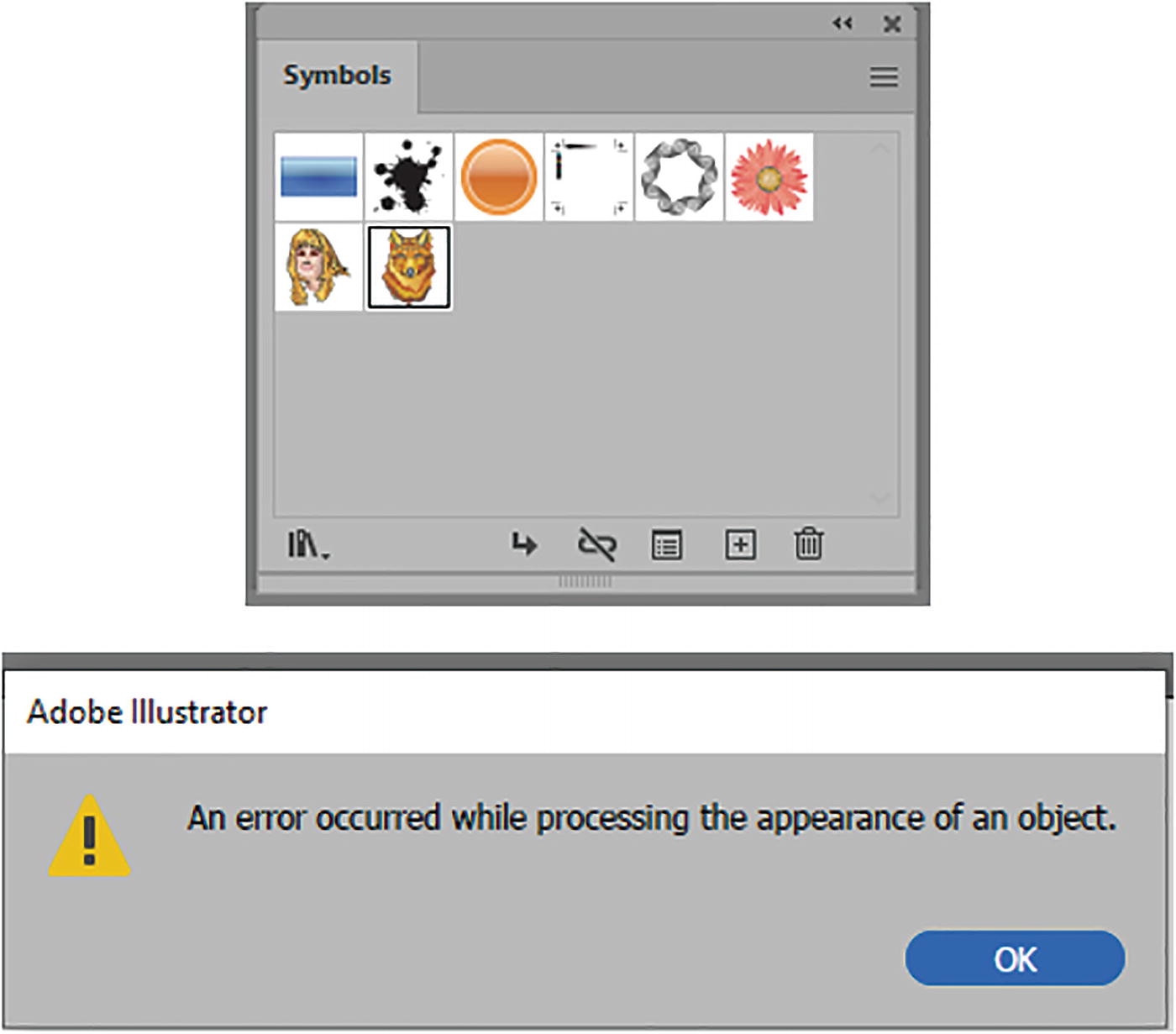
Illustrations with gradients can be saved as symbols, but when blended with the Blend tool they may trigger a warning message unless you expand the gradient first
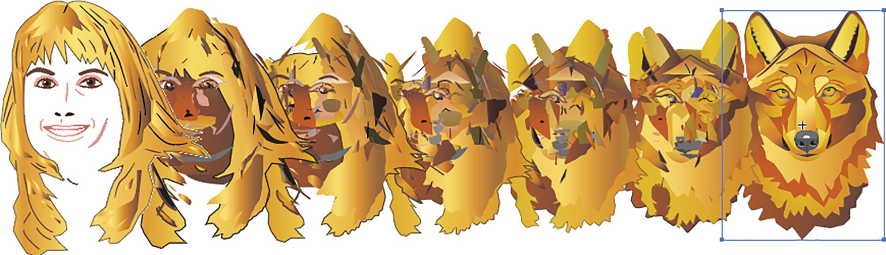
The Blend tool can produce unpredictable results on complex illustrations
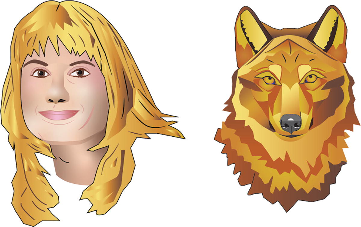
When we are dealing with complex illustrations, we could, as you saw earlier in the chapter, move parts of each illustration around to create a new image. Or, for a smoother blend that is part of your vision, you could use Photoshop.
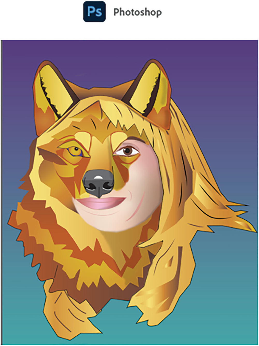
Using Photoshop might be a better option with complex blends

Use Smart Object layers when you want to do custom blends with the brush and eraser tools using layer masks
In this case, I used layer masks and the brush and eraser tools to paint out areas of the woman’s face and the wolf’s face to blend parts of the illustration together. I also made another copy of the wolf layer so that I could scale the wolf’s nose better. The woman’s face-to-nose ratio is wider than the wolf’s, which is more compact, so being able to move separate parts of the wolf around for a better blend is a good option. Lastly, in Photoshop you may want to add a gradient fill background or additional shadows to the face, as on Layer 1, to add additional shadows that were not present in the original illustration. Refer to Figure 6-110.
This project is just something to keep in mind when you are working with complex blends and choosing which Adobe application is better to work with for your illustrations.
You can close any open files at this point as the project is complete.
Summary
The Blend tool is easy to use and can help to generate new shapes or transitions. These can be used as part of a new design or a logo in ways that are planned or sometimes unexpected. You can also use the Blend tool to scale and transform symbols so that you do not have to copy multiple repeating grouped objects or symbols, and then you can update them all in one location while in the Symbols panel and Symbol Editing mode.
However, as the design or illustration becomes more detailed and complex, depending on what your definition of a blend is, you may need to use Photoshop and Smart Object layers to help you achieve your goals.
In the next chapter, we will be looking at a few ways to generate custom patterns and brushes in Illustrator.