RF cables
Coaxial cables
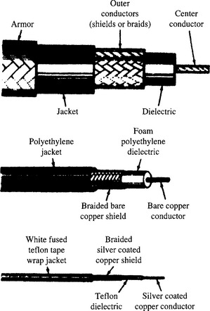
These consist of an inner conductor surrounded by insulation, which in turn is surrounded by a metal sheath. The metal sheath may be solid copper (sometimes, especially in cables with a high power rating, this is corrugated), copper braid or tape (sometimes both), and covered with an outer insulating sheath, which may incorporate armouring. The inner conductor is usually copper, sometimes silver plated, or silver plated steel. The inner insulation may solid, or for a low loss cable, a foamed cellular material, e.g. polythene. For the lowest loss cables the inner insulation may consist of a filament of insulating material wound round the inner - with very few turns per centimetre, or the inner may be supported as it passes through spaced discs of insulation, either arrangement giving a very low loss ‘air-spaced’ cable.
Depending upon the ratio of the diameter of the inner conductor to the internal diameter of the screen and on the permittivity of the insulating material in between, the characteristic impedance of a coaxial cable may be anywhere between about 35 Ω and 120 Ω. The typical velocity of propagation of signals in a coaxial cable is around 60% of that in free space - the speed of light ‘c’ - except in the case of special ‘delay cables’ which have a spiral inner giving a velocity of around c/10. The typical types of construction are illustrated in Figure A5.1.
Ideally, the screen prevents any interference reaching the inner, and by the same token, any signal on the inner leaking out into the environment. Typically, a braided copper screen provides up to some 60 dB of isolation, although cables with a solid outer or a double screen can provide 100 dB or more of screening.
The older ‘RG’ cables (American) or ‘URM’ cables (British ‘Uniradio’) are frequently employed in commercial applications and often prove adequate, but for professional installations, the more modern ‘M17’ cables to MIL-C-17 are to be preferred. For reference, a list of the older cable types, many of which are still readily available, is given below.
50–52 Ω impedance types: RG-58 −142 −174 −178 −188 −196 −213 −214 −217 −218 −223 −316, URM-43 −67 −74 −76 −91 −95 −112 −115 −116
75 Ω types: RG-6 −11 −59 −179, URM-54 −57 −60 −65 −70 −77 −90 −114 −117 93–95 Ω types: RG-62 −180 URM-96 100 Ω DRM68 (2 core), 125 Ω URM64
MIL-C-17 coaxial cables
MIL-C-17 is the US government specification document used to standardize coaxial cables; it has been in use since the 1940s. In the many revisions made to MIL-C-17 over the years, the familiar RG part numbers were superseded by M17 part numbers during the 1970s. The benefits of these more recent revisions are discussed under the following headlines. The most recent and therefore applicable revision is MIL-DTL-17H.
The Times Microwave website contains a complete listing of all current M17 cables. For engineering reference, it also lists the old RG cables. Attenuation and power handling characteristics tables are also presented.
Benefits in using MIL-C-17 coaxial cables
Revision E to MIL-C-17 was released in 1976 to better define the mechanical and electrical requirements for military coaxial cables. For 50-ohm cables, the most important changes were the addition of swept frequency measurements of both attenuation and structural return loss requirements (VSWR) to 22 different cables. Before this revision there were no VSWR requirements, and attenuation requirements were only given at two or three discrete frequencies. Other significant changes are described in the following paragraphs.
Adhesion requirements
MIL-C-17 specifications now contain the minimum and maximum adhesion requirements of the dielectric core to the centre conductor. Prior to revision E, it was possible for a cable to have so little adhesion that the centre conductor in shorter cables could be pulled out of the entire assembly during the stripping operation. Or there could be too much adhesion between the core and the conductor, causing the conductor to break before the dielectric core could be stripped off. With Revision E, a definite criterion has been specified.
Dimensional stability
Revision E required that all cables be manufactured and tested to a specific maximum shrinkback allowance for the dielectric core and the jacket. Temperature extremes can cause shrinkback of the cable jacket which can create a poor termination.
Eccentricity
Before Revision E was implemented, eccentricity requirements applied only to polyethylene dielectrics. Now eccentricity requirements have been identified for other kinds of dielectrics (e.g. PTFE). Cables that meet the eccentricity requirement facilitate the reliable assembly of connector parts and provide low VSWR ratios.
Stress-crack resistance
MIL-C-17 now requires a stress-crack resistance test on all FEP (fluorinated ethylene propylene) and PFA (perfluoroalkoxy) jacketed cables. This test identifies cables with previously undetected residual stress that could result in jacket cracking.
Contamination
Although earlier MIL-C-17 specifications allowed the use of some Type I PVC (poly-vinylchloride) for jackets, Revision F has completely replaced it with Type II PVC, a non-contaminating compound. The plasticizers in Type I PVC can penetrate the braided shield and migrate into the polyethylene dielectric core, causing a large increase in the dielectric loss portion of attenuation, especially at frequencies above 1 GHz.
It should be noted that a cable with a Type I PVC jacket can affect other cables in close contact, even if the other cables all have Type IIa jackets.
Attenuation and structural return loss
MIL-C-17 specifications require that attenuation and structural return loss (VSWR) be completely tested by sweeping 22 different 50-ohm cables over the frequency band for which their use is recommended. Variance in materials or in the manufacturing process can cause periodic discontinuities along a length of coaxial cable which can introduce resonance peaks (spikes). These spikes occur when the discontinuities or changes in electrical characteristics are periodic and at half-wave distances.
When impedance changes occur periodically, there are frequencies in which all of the reflections are in phase, resulting in a large reflected signal or VSWR that is out of proportion to the normal VSWR of the cables and its connectors. Periodic reflections can also cause substantial increase in attenuation at the resonance peaks. In the past, it was very unusual to detect these narrow band, high attenuation spikes when cables were tested for attenuation using the older MIL-C-17D discrete frequency test procedure (generally at 400 MHz and 3 GHz, and also at 10 GHz for RG-214).
Now, however, M17/75-RG214 has continuous swept maximum VSWR and attenuation requirements from 50 MHz to 11 GHz. The maximum VSWR is 1.15: 1 (23 dB SRL) at 100 MHz. Increasing to 60 dB/100 feet at 11 GHz.
Coaxial cables that do not require ‘full band’ swept frequency performance can be procured under separate part numbers in an unswept version. The specifications sheets for these unswept cables recommend that they not be used above 400 MHz. The user must decide which cables will best suit the situation based on cost, application and potential for system growth and improvements.
Cable designations
Cables that are manufactured to MIL-DTL-17H specifications no longer carry the RG designation. For example, RG-214 has been replaced by M17/75-RG214. In the future, any new cable design will be designated by an M17 part number only. In addition to the M17 number, all cables are marked with the manufacturer’s name and government identification number, for example, ‘M17/75-RG214, MIL-C-17 (manufacturer’s name) (manufacturer’s type number)’. Cables that are not marked with this information are not qualified and there is no guarantee of their performance.
MIL-C-17 QPL listing
Only qualified cables should be used for military contracts. All manufacturers of MIL-C-17 cables must obtain qualification approval for their cables. The qualified products are then listed in QPL-17 which is updated periodically throughout the year. Note that all RG numbered cables have been cancelled from MIL-C-17 and only cables with part numbers starting ‘M17/’ should be used for new military contracts. Since there is no longer any control of ‘RG’ specifications, many cables on the market with RG designations may be completely different in construction and performance. The RG cables listed in this catalog, when supplied by Times, are manufactured in accordance with the original specifications sheet released by the military.
Special designs
Although MIL-C-17 covers a broad range of cable types, specialty manufacturers can provide technical assistance in designing specialized cables to meet specific system parameters that cannot be met with existing MIL-C-17 cables.
Tables of characteristics and performance of both MIL-C-17 cables (to the current MIL-DTL-17H issue) and older RG cables can be found at www.timesmicrowave.com (Reproduced by courtesy of Times Microwave Systems)