Passive components
The passive components used in electronic circuits all make use of one or more of the three fundamental phenomena of resistance, capacitance and inductance. Some components depend for their operation on the interaction between one of these electrical properties and a mechanical property, e.g. crystals used as frequency standards, piezo-electric sounders, etc. The following sections look at components particularly in the light of their suitability for use at RFs, and at how they can be inter-connected for various purposes.
Resistance and resistors
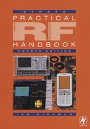
Some substances conduct electricity well; these substances are called conductors. Others called insulators, such as glass, polystyrene, wax, PTFE, etc., do not, in practical terms, conduct electricity at all: their resistivity is about 1018 times that of metals. Even though metals conduct electricity well, they still offer some resistance to the passage of an electric current, which results in the dissipation of heat in the conductor. In the case of a wire of length l metres and cross-sectional area A square metres, the current I in amperes which flows when an electrical supply with an electromotive force (EMF) of E volts is connected across it is given by I = E/((l/A)ρ), where ρ is a property of the material of the wire, called resistivity. The term (l/A)ρ is called the resistance of the wire, denoted by R, so I = E/R; this is known as Ohm’s law. The reciprocal of resistance, G, is known as conductance; G = 1/R, so I = EG.
If a current of I amperes flows through a resistance of R ohms, the power dissipated is given as W = I2R watts (or joules per second). Resistance is often an unwanted property of conductors, as will appear later when we consider inductors. However, there are many applications where a resistor, a resistance of a known value, is useful. Wirewound resistors use nichrome wire (high power types), constantan or manganin wire (precision types). They are available in values from a fraction of an ohm up to about a megohm, and can dissipate more power, size for size, than most other types but are mostly only suitable for use at lower frequencies, due to their self-inductance. For use at high frequencies, film or composition resistors are commonly used. Carbon film resistors were probably the commonest type used in the UK and Europe generally during the twentieth century. They consisted of a pyrolytically deposited film of carbon on a ceramic rod, with pressed-on end caps. Initially, the resistance is a few per cent of the final value: a spiral cut in the film is then made automatically, to raise the resistance to the designed value. Higher power or higher stability requirements can be met by other resistor types using spiralled films of tin oxide or a refractory metal. The spiralling results in some self-inductance, which can be a disadvantage at radio frequencies; perhaps for this reason, carbon composition resistors were popular and widely used in the USA. These were constructed in a phenolic tube with lead-out wires inserted in the ends, and offered good RF performance combined with economy. Cylindrical shaped resistors with axial wire leads, of most types except high power, have now been largely replaced by surface mount resistors. This is especially true of radio frequency equipment, e.g. mobile phones, GPS receivers, etc., where their miniature size and negligible inductance make them the obvious choice. The exception is the development laboratory, where leaded types can still be useful. However, even here the current tendency, when developing a circuit operating at radio frequencies, is to go straight to a printed circuit layout using surface mount components.
Surface mount resistors come in various sizes and ratings. Typical of these are ‘1206’ resistors (0.12 inches long by 0.06 inches wide) rated at 250 mW dissipation and 0603 resistors rated at either 1/16 W or 100 mW, depending upon the manufacturer.
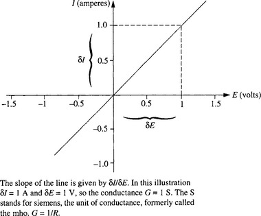
Figure 1.1 Current through a resistor of R ohms as a function of the applied voltage. The relation is linear, as shown, for a perfect resistor. At dc and low frequencies, most resistors are perfect for practical purposes
When two resistors are connected in series, the total resistance is the sum of the two resistances and when two resistors are connected in parallel, the total conductance is the sum of the two conductances. This is summarized in Figure 1.2. Variable resistors have three connections, one to each end of a resistive ‘track’ and one to the ‘wiper’ or ‘slider’. The track may be linear or circular and adjustment is by screwdriver (preset types) or by circular or slider knob. They are mostly used for adjusting dc levels or the amplitude of low frequency signals, but the smaller preset sort can be useful in the lower values up to VHF or beyond.
Capacitors
The conduction of electricity, at least in metals, is due to the movement of electrons. A current of one ampere means that approximately 6242 × 1014 electrons are flowing past any given point in the conductor each second. This number of electrons constitutes one coulomb of electrical charge, so a current of one ampere means a rate of charge movement of one coulomb per second.
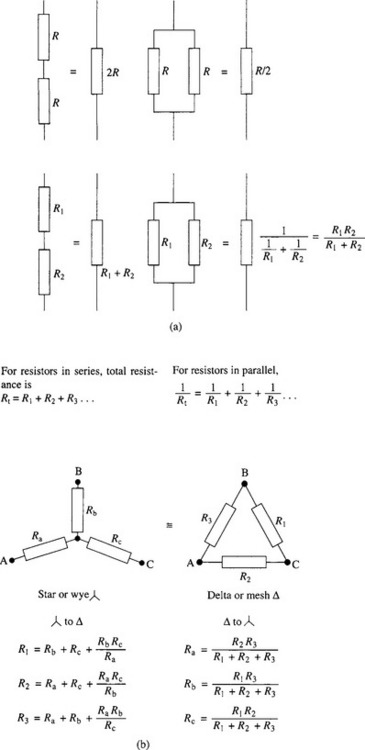
In a piece of metal an outer electron of each atom is free to move about in the atomic lattice. Under the action of an applied EMF, e.g. from a battery, electrons flow through the conductors forming the circuit, towards the positive terminal of the battery (i.e. in the opposite sense to the ‘conventional’ flow of current), to be replaced by other electrons flowing from the battery’s negative terminal. If a capacitor forms part of the circuit, a continuous current cannot flow, since a capacitor consists of two plates of metal separated by a non-conducting medium, an insulator or a vacuum (see Figure 1.3a, b).
A battery connected across the plates causes some electrons to leave the plate connected to its positive terminal, and an equal number to flow onto the negative plate (Figure 1.3c). A capacitor is said to have a capacitance C of one farad (1 F) if an applied EMF of one volt stores one coulomb (1 C) of charge. The capacitance is proportional to A, the area of the plates, and inversely proportional to their separation d, so that C = k(A/d) (provided that d is much smaller than A). In vacuo, the value of the constant k is 8.85 × 10⁻¹², and it is known as the permittivity of free space, ε0. Thus, in vacuo, C = ε0(A/d). More commonly, the plates of a capacitor are separated by air or an insulating solid substance; the permittivity of air is for practical purposes the same as that of free space. An insulator or dielectric is a substance such as air, polystyrene, ceramic, etc., which does not conduct electricity. This is because in an insulator all of the electrons are closely bound to the atoms of which they form part and cannot be completely detached except by an electrical force so great as to rupture and damage the dielectric. However, they can and do ‘give’ a little (Figure 1.3c), the amount being directly proportional to the applied voltage. This net displacement of charge in the dielectric enables a larger charge to be stored by the capacitor at a given voltage than if the plates were in vacuo. The ratio by which the stored charge is increased is known as the relative permittivity, εr. Thus C = ε0εr(A/d), and the stored charge Q = CV. Electronic circuits use capacitors as large as 500000 μF (1 μF = 10−6F), down to as small as 1 pF (one picofarad, 10−12F), whilst stray capacitance of even a fraction of 1 pF can easily cause problems in RF circuits. On the other hand, very large electrolytic capacitors are used to store and smooth out energy in dc power supplies. The amount of energy J joules that a capacitor can store is given by ![]() . (One joule of energy supplied every second represents a power of one watt.)
. (One joule of energy supplied every second represents a power of one watt.)
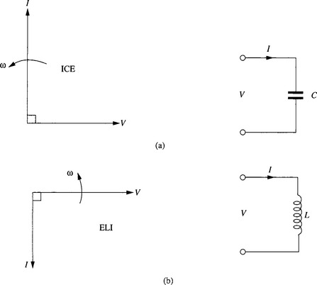
Although dc cannot flow through a capacitor, if a voltage of one polarity and then of the opposite polarity is repeatedly applied to a capacitor, charging current will always be flowing one way or the other. Thus an alternating EMF will cause a current to apparently flow through a capacitor. At every instant, Q = CV, so the greater the rate of change of voltage across the plates of the capacitor, the greater the rate of change of charge, i.e. the greater the current. If we apply a sinusoidal voltage V = Emax sin(ωt)* to a capacitor of CF, Q = CEmax sin(ωt). The charge is a maximum at the peak of the voltage waveform, but at that instant the voltage (and the charge) is momentarily not changing, so the current is zero. It will have been flowing into the capacitor since the previous negative peak of the voltage, being a maximum where the rate of change of voltage was greatest, as it passed through zero. So the current is given by I = C dv/dt = d(CEmax sin(ωt))/dt = ωCEmax cos(ωt). This means that in a capacitor, the phase of the current leads that of the voltage by 90° (see Figure 1.4). You can also see that, for a given Emax, the current is proportional to the frequency of the applied alternating voltage. The ‘reactance’, Xc, of a capacitor determines how much current flows for a given applied alternating voltage E of frequency f (in hertz) thus: I = E/Xc, where Xc = 1/(2pfC) = 1/(ωC). Xc has units of ohms and we can take the 90° phase shift into account by writing Xc = 1/(jωC) = −j/(ωC), where the ‘operator’ j indicates a +90° phase shift of the voltage relative to the current. (j2 = −1, so that 1/j = −j). The -j indicates a −90° phase shift of the voltage relative to the current, as in Figure 1.4. The reciprocal of reactance, B, is known as susceptance; for a capacitor, B = I/Xc = jωC
In addition to large electrolytics for smoothing and energy, already mentioned, smaller sizes are used for ‘decoupling’ purposes, to bypass unwanted ac signals to ground. At higher frequencies, capacitors using a ceramic dielectric will often be used instead or as well, since they have lower self-inductance. Small value ceramic capacitors can have a low (nominally zero) temperature coefficient (‘tempco’), using an NP0† grade of dielectric;
values larger than about 220 pF have a negative temperature coefficient and for the largest value ceramic capacitors (used only for decoupling purposes), tempco may be as high as −15 000 parts per million per degree Celsius. Note that it is inadvisable to use two leaded decoupling capacitors of the same value in parallel. This is because at high frequencies, the inductance of the leads of a capacitor may exhibit a reactance greater than the reactance of the capacitor. Due to the large tolerance on the capacitance of a ceramic decoupling capacitor, at some frequency one may look inductive whilst the other still looks capacitive. They thus present a parallel tuned circuit at that frequency and the resultant high impedance means that the desired decoupling action is absent. Many other dielectrics are available, polystyrene being particularly useful as its negative tempco cancels (approximately) the positive tempco of some ferrite pot inductor cores. Variable capacitors are used for tuned circuits, being either ‘front panel’ (user) controls, or preset types.
Inductors and transformers
A magnetic field surrounds any flow of current, such as in a wire or indeed a stroke of lightning. The field is conventionally represented by lines of magnetic force surrounding the wire, more closely packed near the wire where the field is strongest (Figure 1.5a and b) which illustrates the ‘corkscrew rule’ - the direction of the flux is clockwise viewed along the flow of the current. Note in Figure 1.5a, the convention that a cross on the end of the wire indicates current flowing into the paper. A dot would indicate current flowing out of the paper. In Figure 1.5c, the wire has been bent into a loop: note that the flux lines all pass through the loop in the same direction. With many loops or ‘turns’ (Figure 1.5d) most of the flux encircles the whole ‘solenoid’: if there are N turns and the current is I amperes, then F, the magnetomotive force (MMF, analogous to EMF), is given by F = NI amperes (sometimes called ampere turns). The resultant magnetic flux (analogous to current) is not uniform; it is concentrated inside the solenoid but spreads out widely outside as shown. If a long thin solenoid is bent into a loop or ‘toroid’ (Figure 1.5e) then all of the flux is contained within the winding and is uniform. The strength of the magnetic field H within the toroid depends upon the MMF per unit length causing it. In fact H = I/l amperes/metre, where l is the length of the toroid’s mean circumference and I is the effective current - the current per turn times the number of turns. The uniform magnetic field causes a uniform magnetic flux density, B webers/m2, within the toroidal winding. The ratio B/H is called the permeability of free space μ0, and its value is 4π × 10−7. If the cross-sectional area of the toroid is A m2, the total magnetic flux Φ webers is Φ = BA. If the toroid is wound upon a ferromagnetic core, the flux for a given field strength is increased by a factor μr, the relative permeability. Thus B = μ0μrH. Stated more fully, Φ/A = μ0μrF/l so that:
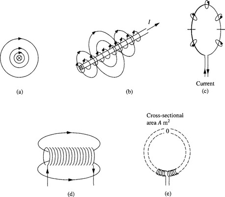
(a) End view of a conductor. The cross indicates current flowing into the paper (a point indicates flow out). By convention, the lines of flux surrounding the conductor are as shown, namely clockwise viewed in the direction of current flow (the corkscrew rule)
(b) The flux density is greatest near the conductor; note that the lines form complete loops, the path length of a loop being greater the further from the wire
(c) Doughnut-shaped (toroidal) field around a single-turn coil
(d) A long thin solenoid produces a ‘tubular doughnut’, of constant flux density within the central part of the coil
(e) A toroidal winding has no external field. The flux density B within the tube is uniform over area A at all points around the toroid
The term lμ0μrA) is called the reluctance S of the magnetic circuit, with units of amperes/weber, and is analogous to the resistance of an electric circuit. The magnetic circuit of the toroid in Figure 1.5e is uniform. If it were non-uniform, e.g. if there were a semicircular ferromagnetic core in the toroid extending half-way round, the total reluctance would simply be the sum of the reluctances of the different parts of the magnetic circuit, just as the total resistance of an electric circuit is the sum of all the parts in series.
When the magnetic field linking with a circuit changes, a voltage is induced in that circuit - the principle of the dynamo. This still applies, even if the flux is due to the current in that same circuit. An EMF applied to a coil will cause a current and hence a flux: the increasing flux induces an EMF in the coil in opposition to the applied EMF; this is known as Lenz’s law. If the flux increases at a rate dφ/dt, then the back EMF induced in each turn is EB = −dφ/dt, or EBtotal = −N dΦ/dt for an N turn coil. However,
and as this is true independent of time, their rates of change must also be equal:
So
The term N2/S, which determines the induced voltage resulting from unit rate of change of current, is called the inductance L and is measured in henrys:
If an EMF E is connected across a resistor R, a constant current I = E/R flows. This establishes a potential difference (pd) V across the resistor, equal to the applied EMF, and the supplied energy I2R is all dissipated as heat in the resistor. However, if an EMF E is connected across an inductor L, an increasing current flows. This establishes a back EMF V across the inductor (very nearly) equal to the applied EMF, and the supplied energy is all stored in the magnetic field associated with the inductor. At any instant, when the current is I, the stored energy is ![]() joules.
joules.
If a sinusoidal alternating current I flows through an inductor, a sinusoidal back EMF EB will be generated. For a given current, as the rate of change is proportional to frequency, the back EMF will be greater, the higher the frequency. So the back EMF is given by
This means that in an inductor, the phase of the voltage leads that of the current by 90° (see Figure 1.4). The ‘reactance’, XL, of an inductor determines how much current flows for a given applied alternating voltage E of frequency f Hz thus: I = E/XL, where XL = 2πfL = ωL. We can take the 90° phase advance of the voltage on the current into account by writing XL = jωL. The reciprocal of reactance, B, is known as susceptance; for an inductor, B = 1/XL = −j/ωL. Note that inductance is a property associated with the flow of current, i.e. with a complete circuit; it is thus meaningless to ask what is the inductance of a centimetre of wire in isolation. Nevertheless, it is salutary to remember (when working at VHF or above) that a lead length of 1 cm on a component will add an inductive reactance of about 6Ω to the circuit at 100 MHz.
In practice, the winding of an inductor has a finite resistance. At high frequencies, this will be higher than the dc resistance, due to the ‘skin effect’ which tends to restrict the flow of current to the surface of the wire, reducing its effective cross-sectional area. The effective resistance is thus an increasing function of frequency. In some applications, this resistance is no disadvantage - it is even an advantage. An RF choke is often used in series with the dc supply to an amplifier stage, as part of the decoupling arrangements. The choke should offer a high impedance at RF, to prevent signals being coupled into/out of the stage, from or into other stages. The impedance should be high not only over all of the amplifier’s operating frequency range, but ideally also at harmonics of the operating frequency (especially in the case of a class C amplifier) and way below the lowest operating frequency as well, since there the gain of an RF power transistor is often much greater. A sectionalized choke, or two chokes of very different values in series may be required. At UHF, an effective ploy is the graded choke, which is close wound at one end but progressively pulled out to wide spacing at the other. It should be wound with the thinnest wire which will carry the required dc supply current and can with advantage be wound with resistance wire. A very effective alternative at VHF and UHF is to slip a ferrite bead or two over a supply lead. They are available in a grade of ferrite which becomes very lossy above 10 MHz so that at RF there is effectively a resistance in series with the wire, but with no corresponding loss at dc. Where an inductor is to form part of a tuned circuit on the other hand, one frequently requires the lowest loss resistance (highest Q) possible. At lower RF frequencies, up to a few megahertz, gapped ferrite pot cores (inductor cores) are very convenient, offering a Q which may be as high as 900. The best Q is obtained with a single layer winding. The usual form of inductor at higher frequencies, e.g. VHF, is a short single-layer solenoid, often fitted with a ferrite or dust iron slug for tuning and sometimes with an outer ferromagnetic hood and/or metal can for screening. A winding spaced half a wire diameter between turns gives a 10 to 30% higher Q than a close spaced winding. Ready made inductors, both fixed, and variable with adjustable cores, are available from many manufacturers, such as Coilcraft, TOKO and others. Surface mount inductors, both fixed and variable, are also readily available from the same and other manufacturers. Some SMD fixed inductors are wirewound, while others are of multilayer chip construction. The latter offer very good stability, but generally have a lower Q than wirewound types.
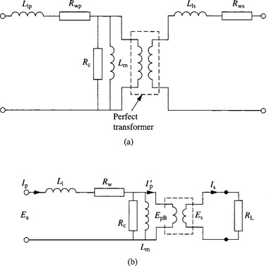
Two windings on a common core form a ‘transformer’, permitting a source to supply ac energy to a load with no direct connection, Figure 1.6. Performance is limited by core and winding losses and by leakage inductance, as covered more fully in Chapter 3.
*ω is the ‘angular velocity’ in radians per second. There are 2p radians in a complete circle or cycle, so (for example) sin(20πt) would be a sinewave of ten cycles per second or 10 Hz, t indicating elapsed time in seconds.
†N750 indicates a tempco of capacitance of −750 parts per million per °C: NP0 indicates a nominally zero tempco.