
12
Reliability Testing
12.1 Introduction
Testing is an essential part of any engineering development programme. If the development risks are high the test programme becomes a major component of the overall development effort, in terms of time and other resources. For example, a new type of hydraulic pump or a new model of a video recording system will normally undergo exhaustive tests to determine that the design is reliable under the expected operating environments and for the expected operating life. Reliability testing is necessary because designs are seldom perfect and because designers cannot usually be aware of, or be able to analyse, all the likely causes of failure of their designs in service. The disciplines described in earlier chapters, when systematically applied, can contribute to a large extent to inherently reliable design. They can also result in fewer failures during testing, and thus reduce the time and cost of the test programme.
Reliability testing should be considered as part of an integrated test programme, which should include:
- Functional testing, to confirm that the design meets the basic performance requirements.
- Environmental testing, to ensure that the design is capable of operating under the expected range of environments.
- Statistical tests, as described in Chapter 11, to optimize the design of the product and the production processes.
- Reliability testing, to ensure (as far as is practicable) that the product will operate without failure during its expected life.
- Safety testing, when appropriate.
It is obviously impracticable to separate entirely the various categories of test. All testing will provide information on performance and reliability, and there will be common requirements for expertise, test equipment and other resources. The different categories of test do have certain special requirements. In particular, statutory considerations often determine safety tests, some of which may have little in common with other tests.
To provide the basis for a properly integrated development test programme, the design specification should cover all criteria to be tested (function, environment, reliability, safety). The development test programme should be drawn up to cover assurance of all these design criteria. It is important to avoid competition between people running the different categories of test, with the resulting arguments about allocation of models, facilities, and priorities. An integrated test programme reduces the chances of conflict.
The development test programme should include:
- Model allocations (components, sub-assemblies, system).
- Requirements for facilities such as test equipment.
- A common test and failure reporting system.
- Test plan and schedule.
One person should be put in charge of the entire programme, with the responsibility and authority for ensuring that all specification criteria will be demonstrated.
There is one conflict inherent in reliability testing as part of an integrated test programme, however. To obtain information about reliability in a cost-effective way, that is quickly, it is necessary to generate failures. Only then can safety margins be ascertained. On the other hand, failures interfere with functional and environmental testing. The development test programme must address this dilemma. It can be very tempting for the people running the development test programme to minimize the chance of failure occurring, in order to make the programme run smoothly and at least cost. However, weaknesses in the design (or in the way it is made) must be detected and corrected before the production phase. This can realistically be achieved only by generating failures. An ideal test programme will show up every failure mode which might otherwise occur in service.
The development test dilemma should be addressed by dividing tests into two main categories:
- Tests in which failures are undesirable (test to success).
- Tests which deliberately generate failures (test to failure).
Statistical testing, functional testing, system level testing and most environmental testing are in category 1. Most reliability testing (and some safety testing) are in category 2, although reliability testing may belong to both categories, depending on the objectives of this testing (see reliability demonstration in Chapter 14). In particular, there must be a common reporting system for test results and failures, and for action to be taken to analyse and correct failure modes. Test and failure reporting and corrective action are covered in more detail later.
The category 2 testing should be started as soon as hardware (and software, when appropriate) is available for test, no later than the VERIFY (preferably earlier) stage of the design for reliability (DfR) process (Chapter 7). The effect of failures on schedule and cost increases progressively, the later they occur in the development programme (see Figure 7.1). Therefore tests should be planned to show up failure modes as early as is practicable. The category 1 testing is more appropriate for the VALIDATE stage of the DfR process, although test to failure is not uncommon at this stage as well.
Engineering development testing methods are described in more detail in O’Connor (2001).
12.2 Planning Reliability Testing
12.2.1 Using Design Analysis Data
The design analyses performed during the design phase (CAE, reliability prediction, FMECA, stress analysis, parameter variation analysis, sneak circuit analysis, FTA) described in Chapters 6, 7 and 9, as well as any earlier test results, should be used in preparing the reliability test plan. These should have highlighted the risks and uncertainties in the design, and the reliability test programme should specifically address these. For example, if the FMECA shows a particular failure mode to be highly critical, the reliability test programme should confirm that the failure is very unlikely to occur within the use environment and lifetime. Inevitably the test programme will also show up failure modes and effects not perceived during the design analyses, otherwise there would be little point in testing. Therefore, the test programme must cover the whole range of use conditions, including storage, handling, testing, repair and any other aspect which might affect reliability.
12.2.2 Considering Variability
We have seen in Chapters 5 and 11 how variability affects the probability of failure. A major source of variability is the range of production processes involved in converting designs into hardware. Therefore the reliability test programme must cover the effects of variability on the expected and unexpected failure modes. If parameter variation analyses or statistical tests have been performed, these can be very useful in planning reliability tests to confirm the effects of variation. However, to ensure that the effects of variability are covered as far as is practicable, it is important to carry out reliability testing on several items. The number of systems to be tested must be determined by considering:
- The extent to which the key variables can be controlled.
- The criticality of failure.
- The cost of test hardware and of testing.
Only rarely will fewer than four items be adequate. For fairly simple systems (transistors, fasteners, hydraulic check valves, etc.) it might be relatively easy to control the few key variables and the criticality of failures might be relatively low. However, it is not expensive to test large quantities. For systems of moderate complexity (e.g. automobiles, TV sets, machine tools) it is much harder to control key variables, since there are so many. Every interface within the system introduces further sources of variability which can affect reliability. Therefore it is very important to test a relatively large number, five to 20 being a typical range. For complex systems (aero engines, aircraft, etc.) hardware and test cost tend to be the major constraints, but at least four items should be subjected to a reliability test. Reliability testing of fewer than four might be appropriate for large, expensive, complex systems which will be manufactured in very small quantities (e.g. spacecraft, ships, power stations), of which the items tested will be used operationally.
The effects of known sources of variability can sometimes be assessed by testing items in which variable parameters (e.g. dimensions, process variables) have been deliberately set at worst case values. Statistical design of experiment (DOE) and other statistical engineering optimization techniques, as described in Chapter 11, should be used to analyse the effects of multiple sources of variation.
12.2.3 Durability
The reliability test programme must take account of the pattern of the main failure modes with respect to time (or cycles, distances, etc., with which the time dimension is associated).
If the failure modes have increasing hazard rates, testing must be directed towards assuring adequate reliability during the expected life. Therefore reliability tests must be of sufficient duration to demonstrate this, or they must be accelerated. Accelerated testing is covered later. Generally speaking, mechanical components and assemblies are subject to increasing hazard rates, when wear, fatigue, corrosion or other deterioration processes can cause failure. Systems subject to repair and overhaul can also become less reliable with age, due to the effects of maintenance, so the appropriate maintenance actions must be included in the test plan.
12.3 Test Environments
The reliability test programme must cover the range of environmental conditions which the product is likely to have to endure. The main reliability-affecting environmental factors, affecting most products, are:
Temperature.
Vibration.
Mechanical shock.
Humidity.
Power input and output.
Voltage (electronics).
Dirt/dust.
Contaminants.
People.
In addition, electronic equipment might be subjected to:
Electromagnetic effects (EMI).
Voltage transients, including electrostatic discharge (ESD).
Certain other environments can affect reliability in special cases. Examples are:
Radiation (ultraviolet, cosmic, X-rays).
Lubricant age or contamination.
High altitude.
Space vacuum.
Industrial pollution.
Electromagnetic pulse (lightning, nuclear).
Salt spray.
Fungus.
High intensity noise.
Noxious gases.
US MIL-STD-810, UK Defence Standard 07-55 and ISO/IEC60068 (see Bibliography) provide test methods appropriate to most of these environmental conditions. However, these standards do not address reliability directly, since the objective is to show that the product will not fail or incur damage under the test conditions. Also, most of the tests do not require that the equipment be operating during the tests, and the tests are single-environment, not combined.
The environmental test programme will address the formal environmental test requirements, particularly when these are necessary in order to comply with legal or contractual requirements. The environmental aspects of the reliability test programme must take account of the environmental requirements stated in the design specification and of the planned environmental test. However, to be effective as a means of ensuring a reliable product, the environmental aspects of reliability testing must be assessed in much greater detail.
The environmental aspects of reliability testing must be determined by considering which environmental conditions, singly and in combination with others, are likely to be the most critical from the reliability point of view. In most cases, past experience and codes of practice will provide adequate guidelines. For example, US MIL-HDBK-781 provides information on how to assess environmental conditions and to design the tests accordingly. Typically, a reliability test environment for an electronic system to be used in a vehicle or aircraft might be as shown in Figure 12.1. Such testing is known as combined environmental reliability testing (CERT).

Figure 12.1 Typical CERT environmental cycles: electronic equipment in a vehicle application.
Test chambers are available for CERT testing, particularly for electronic systems. These include facilities for temperature cycling and for vibration input to the unit under test by locating the chamber over a floor-mounted vibrator, with a movable or flexible floor for the chamber. Electrical signals, (power, control and monitoring) can be fed through connectors in the chamber wall. Special chambers can be provided with other facilities, such as humidity and reduced pressure. Control of the chamber conditions can be programmed, and the unit under test can be controlled and monitored using external equipment, such as programmable power supplies, data loggers, and so on.
Figure 12.2 shows a typical CERT facility.
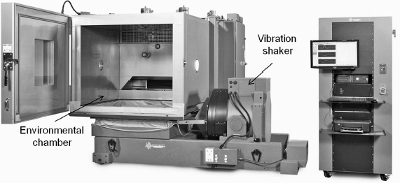
Figure 12.2 CERT test facility (Reproduced by permission of Thermotron Industries).
When past experience on standard methods is inappropriate, for example for a high risk product to be used in a harsh environment, the test environments must be carefully evaluated, particularly:
- Rate of change of conditions, not just maximum and minimum values. For example, a high rate of change of temperature can cause fracture or fatigue due to thermal mismatch and conductivity effects.
- Operating and dormant conditions in relation to the outside environment. For example, moisture-assisted corrosion might cause more problems when equipment is idle than when it is operating.
- The effects of combined environments, which might be much more severe than any one condition. Statistical experiments (Chapter 11) can be used to evaluate these effects.
- Direction and modes of vibration and shock. This is dealt with in more detail later.
- Particular environmental conditions applicable to the product, such as handling, storage, maintenance and particular physical conditions.
12.3.1 Vibration Testing
Adequate vibration testing is particularly important for products which must survive vibration conditions. However, specifying and obtaining the right conditions can be difficult, and it is easy to make expensive mistakes.
The main principles of effective vibration testing are:
- Vibration should be input to the device under test (DUT) through more than one axis, preferably simultaneously.
- Vibration inputs should cover the complete range of expected frequencies and intensities, so that all resonances will be excited.
- In most applications vibration input should be random, rather than swept frequency, so that different resonances will be excited simultaneously (see below).
- Test fixtures to mount the DUT to the vibration tables should be designed so that they do not alter the vibration output (no fixture resonances or damping). Whenever practicable, the DUT should be mounted directly on to the vibrator platform.
The simplest vibration test is a fixed frequency ‘shake’, usually with a sine wave input. However, this is of little value in reliability testing. Modern vibrators can be programmed to generate any desired profile.
Swept frequency sine testing is useful for resonance searches, to enable the design to be modified if unacceptable resonances are detected.
Peak acceleration for a given frequency of sine wave vibration can be calculated using the formula:
![]()
where: A = peak acceleration (g).
f = frequency (Hz).
D = peak-to-peak displacement (mm) for example, if f = 50 Hz and D = 2 mm then A = 10 g.
Another type of sinusoidal vibration is sine-dwell, where the DUT is vibrated for a period of time at its resonant frequency in order to generate the maximum amount of stress.
Alternatively, the spectrum could be a random input within a specified range and density function. Random vibration testing in which the input contains many frequencies is more effective than swept frequency for reliability testing, to show up vibration-induced failure modes, since it simultaneously excites all resonances. It is also more representative of real life.

Figure 12.3 Road transport vibration levels.
The unit of measurement for random vibration inputs with continuous spectra is power spectral density (PSD). The units are g2/Hz. Typically inputs of up to 0.1 g2/Hz are used for equipment which must be shown to withstand fairly severe vibration, or for screening tests on assemblies such as electronic equipment. A typical random vibration spectrum is shown in Figure 12.3.
It is important to apply power to electrical or electronic equipment and to monitor its performance while it is being vibrated, so that intermittent failures can be detected and investigated.
Since dynamic responses are usually affected more by resonances within the product, due to the design and to production variation, than by the input spectrum from the vibrator, it is seldom cost-effective to simulate accurately the operating environment, even if it is known in detail. Since the objective in vibration reliability testing is to excite resonances simultaneously, and since almost any random spectrum will do this, test costs can be minimized by permitting large spectral tolerances, for example ± 6 dB.
Vibration and shock testing are described in more detail in O'Connor (2001), Harris (2010) and Steinberg (2000).
12.3.2 Temperature Testing
The most common types of temperature tests are constant temperature, temperature cycling and thermal shock. Constant temperature tests are more common in the electronics industry and are designed to evaluate the operational or storage capabilities of the product under extreme low or extreme high temperatures. Temperature cycling and thermal shock are intended to subject the product to low cycle fatigue (as opposed to high cycle fatigue experienced during vibration). Due to mismatch between coefficients of thermal expansion for different materials, thermal cycling causes stress cycling which often results in fatigue failures. Thermal cycling and thermal shock are defined by the extreme values (high and low temperatures) and the rate of transition, which is typically much higher in thermal shock tests. Temperature testing for electrical and electronic equipment is particularly important, since reliability can be affected by operating temperature (Chapter 9) and by thermal cycling. In most cases equipment should be powered and operated during temperature testing, otherwise the tests will be unrepresentative of the thermal patterns and gradients in use. It should also be monitored continuously to ensure that intermittent failures are detected.
12.3.3 Electromagnetic Compatibility (EMC) Testing
EMC testing is very important for electronic systems, since data corruption due to electromagnetic interference (EMI) or from voltage transients in power supplies can have serious consequences (see Chapter 9). The equipment must be subjected to EMI and transients to confirm that it will perform without failure under these conditions. The levels of EMI and transient waveforms must be ascertained by evaluating or measuring the operating environment, or they might be specified.
Internally induced EMI and transients must also be protected against, and tests to ensure that transmitted EMI is within limits might also be necessary.
EMI/EMC testing methods are described in US MIL-STD-462D and IEC 61000 (see Bibliography).
12.3.4 Other Environments
See O'Connor (2001).
12.3.5 Customer Simulation Testing
Functional, environmental, reliability and safety tests are all designed to demonstrate that the equipment will meet its design parameters. In general these tests are carried out by people with extensive engineering backgrounds. Such people are, with the best will in the world, often far removed from the average user of the equipment. It is therefore important, particularly in the field of consumer products (televisions, copiers, washing machines, etc.), that some reliability testing is conducted using people who are more nearly representative of typical customers or by trial customers. This is called ‘beta’ testing. This approach is very useful in highlighting failure modes that do not show up when the equipment is used by experienced personnel or in non-representative environments. For example, car companies often use ‘fleet’ vehicles (police, rental and delivery) to test new parts and systems. These vehicles accumulate mileage much faster than the ordinary cars, therefore potential design problems may be discovered much sooner.
12.4 Testing for Reliability and Durability: Accelerated Test
In Chapters 8 and 9 we reviewed how mechanical, electrical and other stresses can lead to failures, and in Chapter 5 how variations of strength, stresses and other conditions can influence the likelihood of failure or duration (time, distance, cycles, etc.) to failure. In this section we will describe how tests should be designed and conducted to provide assurance that designs and products are reliable and durable in service.
12.4.1 Test Development
For most engineering designs we do not know what is the ‘uncertainty gap’ between the theoretical and real capabilities of the design and of the products made to it, for the whole population, over their operating lives and environments. The effects of these uncertainties can seldom be evaluated with confidence by any of the design analysis methods described in Chapter 7. How then can we plan a test programme that will reduce the uncertainty gap to an extent that we can be assured of reliability and durability, whilst taking due account of practical constraints like cost and time?
The conventional approach to this problem has been to treat reliability as a functional performance characteristic that can be measured, by testing items over a period of time whilst applying simulated or actual in-service conditions, and then calculating the reliability achieved on the test. For example, time of operation divided by the number of failures is the estimated mean time between failures (MTBF). This approach will be discussed in Chapter 14. However, these methods are fundamentally inadequate for providing assurance of reliability. The main reason is that they are based on measuring the reliability achieved during the application of simulated or actual stresses that are within the specified service environments, in the expectation (or hope) that the number of failures will be below the criterion for the test. This is the wrong answer to the problem expressed above.
The correct answer is straightforward: we must test to cause failures, not test to demonstrate successful achievement. This concept is well accepted in many industries, particularly where mechanical strength testing is involved. It is important to remember that most of the failures in modern electronics are also of mechanical nature. To derive the strength and fatigue properties of materials, samples are tested to failure. As explained in Chapter 8, we cannot precisely determine the strength of, say, an alloy or a plastic material by theoretical analysis, only by testing samples to failure. If we design a component using such a material, we can analyse the stresses using methods like FEA and we can calculate the strength using the material properties derived from published data or, where necessary, the tests to failure. If the design is simple and there is an adequate margin between stress and strength, we might decide that no further testing is necessary. If, however, constraints such as weight force us to design with smaller margins, and if the component's function is critical (like supporting an aircraft engine), we might well consider it prudent to test some quantity to failure. We would then expect that failures would occur only well beyond the expected maximum stress/minimum life, to provide an adequate margin of safety to take account of the uncertainties and variations in this kind of design and application.
However, let us assume that a system is being designed, and the specified maximum temperature for satisfactory operation is 40 °C. Up to what temperature should the prototype be tested? Some inexperienced (and some experienced) engineers answer that 40 °C should be the maximum test temperature, because any temperature above that would not be ‘representative’ of specified conditions. Therefore any failures that occur above that temperature would not be considered relevant.
However, suppose that a prototype was tested at 42 °C, and failed. Should we ignore this? Might this failure occur at 35 °C on another unit built to the same drawings (effect of variability), or might it occur on this unit six months into the warranty period (effect of a time-dependent failure mechanism)? Might it occur at a combination of 35 °C and a small, within-specification, increase in supply voltage? Can we really be sure that the failure at 42 °C is not relevant, just because the thermal stress applied was not ‘representative’?
If the failure occurred at a temperature 2 °C above the specified limit it is unlikely that it would be ignored (though this does happen). Suppose, however, that failure occurred at 50 °C, or 60 °C? At what stress do we decide that the level is so high that we can ignore failures? Should we even be testing at stresses so much higher than the maximum specified values?
The answer is that these are the wrong questions. The clue is in the earlier questions about the possible cause of the failure. When failures occur on test we should ask whether they could occur in use. The question of relevance can be answered only by investigating the actual physical or chemical cause of failure. Then the questions that must be asked are:
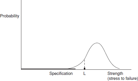
Figure 12.4 Stress, strength and test failures (1).
- Could this failure occur in use (on other items, after longer times, at other stresses, etc.)?
- Could we prevent it from happening in use?
The stress/es that were applied are relevant only in so far as they were the tools to provide the evidence that an opportunity exists to improve the design. We have obtained information on how to reduce the uncertainty gap. Whether the opportunity is taken is a management issue, in which other aspects such as cost, weight, time, and so on must be considered.
The uncertainty described above is shown in Figure 12.4. If we consider only one stress and the failures it might cause, the stress to failure distribution of production items might be as shown. As a simple example, this might be the operating temperature at which an electronic component malfunctions, or the pressure at which a seal begins to leak. As discussed in Chapter 2, the exact nature of this distribution is almost always uncertain, particularly in the tails, which are the most important areas as far as reliability and durability are concerned.
Suppose that the first test failure occurs at stress level L. At this stage we might have only a few items to test, maybe only one. We can state that the strength of this item represents a point on the distribution, but we cannot say whether it was an average strength item, a strong one or a weak one. The only way to find out the nature of the strength distribution is to test more items to failure, and to plot and analyse the results. Inevitably most of the items tested will be near to the average, because that is where most of the population will lie. Therefore, it is unlikely that any item tested will represent the weakest in the future population.
However, if we analyse the actual cause of the failure, by whatever means is appropriate, and take action to strengthen the item, then in effect we will move the strength distribution to the right. We still do not know its shape, but that is not what is important. We just want to move it out of the way. We are engineers, not theoretical scientists or statisticians, so we can use high stresses in place of large samples. Whilst scientific knowledge of the cause and effect relationships that affect reliability and durability is obviously necessary in order to create designs and to determine how to improve them, this is appropriate to determining where distributed values are centred, and sometimes the variation near the centre. In the electronics example, we might use a higher rated component, or add a heat sink. For the seal we might change the material or the dimensions, or add a second seal, or reduce the pressure. The system will therefore be made more reliable.
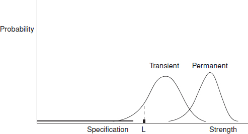
Figure 12.5 Stress, strength and test failures (2).
For many items subjected to stress tests, particularly electronic systems, two types of failure can occur: transient (or operating) failures and permanent failures. If a transient failure occurs at some stress level the correct operation will be restored if the stress is reduced. Permanent failures are those from which the operation does not recover when the stress is reduced. For stresses like temperature, power voltage level, and so on, which might have low or negative limiting values, failures might occur at high and at low levels, and these will of course have different physical causes from those at the high levels. For a population of items the stresses at which the failures occur will be distributed. The general case is illustrated in Figure 12.5.
If the failure is due to a wearout mechanism, say wear of a bearing or fatigue of a component attachment, the horizontal axis of the distribution will represent time (or cycles), for any particular stress value. In addition to the uncertainty regarding the stress and strength, we now have the further uncertainty of time. Failure on test after time t at stress level L will represent one point on an unknown three-dimensional distribution (Figure 12.6). As Figure 12.6 illustrates, an important feature of wearout mechanisms is that the resulting distributions of times to failure become wider as damage accumulates, thus further increasing the uncertainty. To obtain a full understanding might require more testing, with larger samples. However, the same principle applies: we are not really interested in the shapes of distributions. We just want to make the design better, if it is cost effective to do so.

Figure 12.6 Stress, strength and test failures (3): wearout failures.
In most engineering situations failures are caused by combinations of stresses and strength values, not just by one stress and one strength variable. Some might be time-dependent, others not. Using the examples above:
- The stresses applied to the electronic component could be a combination of high temperature operation, high temperature rate of change after switch-on, rate of on–off cycles, humidity when not operating, power supply voltage level, and vibration. The resisting strengths might be mechanical integrity of the internal connections, thermal conductivity of the encapsulating material, absence of defects, and so on.
- For the seal, the stresses and other variables might be oil temperature, pressure, pressure fluctuations, oil conditions (viscosity, cleanliness, etc.), shaft axial and radial movement, vibration, tolerances between moving parts, tolerances on seal grooves and seal dimensions, and so on.
Between any two or more of these variables there might also be interactions, as described in Chapter 11.
Therefore, even for relatively simple and common failure situations like these, there is not just one distribution that is important, but a number of possible distributions and interactions. What might cause a transistor, capacitor or seal to fail in one application might have a negligible effect in another, or a component that has worked well in previous applications might cause problems in a new but similar one. This is how life is in engineering!
This reasoning leads to the main principle of development testing for reliability. We should increase the stresses so that we cause failures to occur, then use the information to improve reliability and durability. This is particularly true in the DESIGN-ANALYZE-VERIFY cycle of the DfR process (Chapter 7). Clearly there will be practical limits to the stresses applied. These limits are set by:
- The fundamental limits of the technology. For example, there is no point in testing an electronic system at temperatures above the melting point of the solder used.
- The limits of the test capability, such as the maximum temperature of the test chamber.
The logic that justifies the use of very high ‘unrepresentative’ stresses is based upon four aspects of engineering reality:
- The causes of failures that will occur in the future are often very uncertain.
- The probabilities of and durations to failures are also highly uncertain.
- Time spent on testing is expensive, so the more quickly we can reduce the uncertainty gap the better.
- Finding causes of failure during development and preventing recurrence is far less expensive than finding new failure causes in use.
It cannot be emphasized too strongly: testing at ‘representative’ stresses, in the hope that failures will not occur, is very expensive in time and money and is mostly a waste of resources. It is unfortunate that nearly all standardized approaches to stress testing (these standards are discussed later) demand the use of typical or maximum specified stresses. This approach is widely applied in industry, and it is common to observe prototypes on long-duration tests with ‘simulated’ stresses applied. For example, engines are run on test beds for hundreds of hours, cars are run for thousands of miles around test tracks, and electronic systems are run for thousands of hours in environmental test chambers. Tests in which the prototype does not fail are considered to be ‘successes’. However, despite the long durations and high costs involved, relatively few opportunities for improvement are identified, and failures occur in service that were not observed during testing. An important point to realize in this context is that a failure that is generated by a stress level during test might be generated by a different stress (or stresses) in service. For example, a fatigue failure caused by a few minutes vibration on test might be caused by months or years of temperature cycling in service. The vibration stress applied on test might be totally unrepresentative of service conditions. Once again, though, the principle applies that the ‘unrepresentative’ test stress might stimulate a relevant failure. Furthermore, it will have done so much more rapidly than would have been the case if temperature cycling had been applied. However it is more common in test engineering to subject a product to the same types of environment as in the field, only at higher levels (accelerated test).
12.4.2 Accelerated Test
Product testing at accelerated levels is very common in many industries. Testing a product above the level of its specification makes it fail sooner and provides additional information about its strength. It also helps to lower the cost of development by reducing test time and thus helping to deliver products to market in the shortest possible time.
The same environments discussed in Section 12.3 (temperature, vibration, humidity, etc.) can be used in accelerated testing. For example, making a product operate at elevated temperatures or subjecting it to higher vibration levels will shorten its test time.
The theoretical concept of the effect of accelerated test on a product's life is shown in Figure 12.7. Higher stress levels shorten the expected product life and increase the expected failure rate at all phases of the bathtub curve.
Understanding the potential failure mechanisms and product design limits is critical to developing a successful accelerated test. Figure 12.8 shows the typical stress ranges and the expected types of failures. These stress limits can be two-sided (e.g. temperature ranges) as shown in Figure 12.8 or one-sided (e.g. vibration or voltage). Increasing the stress beyond the product's design limits may precipitate failures which would not be representative of the field environment. For example, plastic parts may exceed their glass transition points or even melt at high ambient temperatures, something which would not happen under normal usage conditions. These types of failures are often referred as foolish failures and should be avoided during product testing. Accelerated stress levels should be chosen that so they accelerate the ‘realistic’ failure modes, which are expected in the field. Understanding of the technology, previous experience with similar products, and design team inputs should help in the process of determining the appropriate stress levels. Also proper use of DOE (Chapter 11) is critical at this step. A similar concept as applied to manufacturing stress screening is described in Chapter 15 (Figure 15.8). Accelerated test models and how to apply them to the test development will be discussed in Chapter 13. Accelerated stress testing can provide quantitative cause and effect information when the mechanisms of failure are already understood (e.g. material fatigue), and when the tests are planned specifically to provide such information. We can perform statistically designed experiments (Chapter 11), applying accelerated stresses to explore their effects. However, tests to provide such information require larger samples, more detailed planning and more time, and therefore would cost more than would be the case in the accelerated test approach described above. We must decide whether we need the extra information that more ‘scientific’ or statistical tests can provide. In many cases the information from accelerated tests, as described above, coupled with engineering knowledge, is sufficient to enable us to take appropriate action to improve designs and processes. However, sometimes we need to obtain more detailed information, especially when the cause and effect relationships are uncertain.

Figure 12.7 Effect of accelerated test on the bathtub curve.
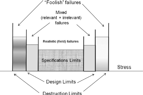
Figure 12.8 Stress ranges and types of failures.
Electronic systems have been subjected to accelerated temperature and vibration stresses not only in development, but also for production units. This is called environmental stress screening (ESS). Other names have been used for the same approach, including STRIFE (stress + life). ESS methods have been standardized to some extent as a result of the guidelines published by the US Institute of Environmental Sciences and Technology (IEST) and ISO/IEC 61163. Also, apart from the fairly limited stress combinations applied in ESS or CERT, the stresses are usually applied singly. The objective is to simulate the expected worst-case service environments, or to accelerate them by only moderate amounts. The general principle usually applied to all of these methods has been to test the item to ensure that it does not fail during the test. This is not consistent with the approach discussed above, and in more detail below.
12.4.3 Highly Accelerated Life Testing
A test in which stresses applied to the product are well beyond normal shipping, storage and in-use levels is called Highly Accelerated Life Testing (HALT). The principle was developed by an American engineer, Dr Gregg Hobbs, and it is fully described in McLean (2009). HALT is usually conducted in specially designed environmental HALT chambers. They can combine wide temperature ranges with fast transition and high GRMS random vibration. A HALT chamber can provide a temperature range of [−100; +200] °C with up to 100 GRMS repetitive shock 6 degree of freedom vibration. Repetitive shock vibration tables typically allow limited control over the shape of the random vibration spectrum. In HALT we make no attempts to simulate the service environment, except possibly as the starting point for the step-stress application. This type of accelerated test with no clear acceleration model is often referred as Qualitative Accelerated Test (as opposed to Quantitative Accelerated Test, discussed in the previous section). No limits are set to the types and levels of stresses to be applied. We apply whatever stresses might cause failures to occur as soon as practicable, whilst the equipment is continually operated and monitored. We then analyse the failures as described above, and improve the design. These design improvements can expand the design limits (Figure 12.8) moving them further away from the specification limits, thus reducing the chances of failure.
By applying stresses well in excess of those that will be seen in service, failures are caused to occur much more quickly. Typically the times or cycles to failure in HALT will be several orders of magnitude less than would be observed in service. Failures which might occur after months or years in service are stimulated in minutes by HALT. Also, the very small sample usually available for development test will show up failure modes that might occur on only a very small proportion of manufactured items. Therefore we obtain time compression of the test programme by orders of magnitude, and much increased effectiveness. This generates proportional reductions in test programme cost and in time to market, as well as greatly improved reliability and durability.
It is important to appreciate that reliability/durability values cannot be demonstrated or measured using HALT. An accelerated stress test can provide such information only if the cause of failure is a single predominant mechanism such as fatigue, we know exactly what single type of stress was applied, and we have a credible mathematical relationship to link the two. Such relationships exist for some failure mechanisms, as described in Chapters 8 and 9. However, since HALT applies a range of simultaneous stresses, and since the stress profiles (particularly the vibration inputs) are complex and unrecorded, such relationships cannot be derived. In HALT we are trying to stimulate failures as quickly as possible, using highly ‘unrepresentative’ stresses, so it is impossible and misleading to relate the results to any quantitative reliability/durability requirement such as MTBF, MTTF, and so on.
The HALT approach can be applied to any kind of product or technology. For example:
- Engines, pumps, power transmission units such as gearboxes, and so on.
- Start tests with old lubricants or other fluids (coolants, hydraulics, etc.), rather than new.
- Run at low fluid levels.
- Use fluids that are heated, cooled or contaminated.
- Use old filters.
- Misalign shafts, bearings, and so on.
- Apply out-of-balance to rotating components.
- Electro-mechanical assemblies such as printers, document, material or component handlers, and so on.
- Apply high/low temperatures, vibration, humidity/damp, and so on.
- Use components with out-of-tolerance dimensions.
- Misalign shafts, bearings, and so on.
- Use papers/documents/materials/components that exceed specifications (thickness, weight, friction, etc.).
- Small components or assemblies such as electronic packages, mechanical latches, switches, transducers, and so on.
- Apply high/low temperatures, vibration, humidity/damp, and so on.
- Apply high frequency vibration by fixing to suitable transducers, such as loudspeaker coils, and driving with an audio amplifier.
12.4.4 Test Approach for Accelerated Test
The approach that should be applied to any accelerated test programme for reliability/durability should be:
- Try to determine, as far as practicable, what failures might occur in service. This should have been performed during design analysis and review, particularly during the quality function deployment (QFD) and failure modes, effects and criticality analysis (FMECA) (Chapter 7).
- List the application and environmental stresses that might cause failures. Use Chapters 8 and 9 for guidance.
- Plan how the stresses that might stimulate foreseeable and unforeseen failures can most effectively be applied in test. Set up the item (or items) to be tested in the test chamber or other facility so that it can be operated and monitored.
- Apply a single stress, at or near to the design maximum, and increase the level stepwise until the first failure is detected. This approach is called step-stress accelerated testing.
- Determine the cause and take action to strengthen the design so that it will survive higher stresses. This action might be a permanent improvement, or a temporary measure to enable testing to be continued.
- Continue increasing the stress(es) to discover further failure causes (or the same cause at a higher stress), and take action as above.
- Continue until all of the transient and permanent failure modes for the applied stress are discovered and, as far as technologically and economically practicable, designed out. Repeat for other single stresses.
- Decide when to stop (fundamental technology limit, limit of stress that can be applied, cost or weight limit).
- Repeat the process using combined stresses, as appropriate and within the equipment capabilities (temperature, vibration, power supply voltage, etc.).
Note that there is a variety of different test profiles besides step-stress, which can be utilized in HALT. The selection of stresses to be applied, singly or in combination, is based upon experience and on the hardware being tested, and not on specifications or standards.
12.4.5 HALT and Production Testing
HALT does not only provide evidence on how to make designs more robust. It also provides the information necessary to optimize stress screens for manufacturing. The basic difference between the objectives of accelerated test in development and in manufacturing is that, whilst we try to cause all development test items to fail in order to learn how to improve the design, we must try to avoid damaging good manufactured items, whilst causing weak or defective ones to fail so that they can be corrected or segregated. The knowledge that we gain by applying the full HALT sequence, including the design ruggedization, can be used to design a stress test regime that is optimized for the product, and which is far more effective than conventional production testing. This is called highly accelerated stress screening (HASS). HASS provides the same benefits in manufacturing as HALT does in development, in greatly increasing the effectiveness of manufacturing screens whilst reducing test cost and time. We will describe manufacturing testing in detail in Chapter 15.
HALT and HASS represent an integrated approach to testing to ensure that both the design and the manufacturing processes will generate highly reliable products, at minimum cost and time. Conventional, separate, approaches to development and manufacturing tests do not assure this integration, and therefore can result in much lower reliability and higher costs.
| Important Variables, Effects, etc. | DoE/HALT? |
| Parameters: electrical, dimensions, etc. | DoE |
| Effects on measured performance parameters, yields | DoE |
| Stress: temperature, vibration, etc. | HALT |
| Effects on reliability/durability | HALT |
| Several uncertain variables | DoE |
| Not enough items available for DoE | HALT |
| Not enough time available for DoE | HALT |
12.4.6 DoE or HALT?
Statistical experiments and HALT are complementary approaches in development testing. Table 12.1 gives some guidance on which approach to select for particular situations.
Note that these are by no means clear-cut criteria, and there will often be shades of grey between them. We must decide on the most appropriate method or combination of methods in relation to all of the factors: risks, knowledge, costs, time.
12.5 Test Planning
Testing is an integral part of product development and can begin as early as the DESIGN phase of the DfR process (Chapter 7). However most testing is done during the VERIFICATION and VALIDATION stages. In the earlier development phases testing is usually directed at addressing particular design concerns or failure mechanisms. For example a circuit board can be tested to 1000 cycles of thermal shock to estimate the fatigue life of lead-free solder joints or a heavy device can be subjected to random vibration to test the strength of a mounting bracket. Test to failure followed by life data analysis (Chapter 3) would be the best way to explore design limits (Figure 12.8) at the system, sub-system, or component level.
At the VALIDATION stage testing is typically done on a system level in order to confirm that it is ready for production. Due to schedule constraints and time to market pressure at this phase the product is often tested to prove that the design is ‘good enough’ for the expected environment. This is often done as a test to success and would often combine a gamut of tests simulating all possible field environments. Planning such a comprehensive system validation test requires a variety of considerations including understanding of the reliability specifications, field environments, possible failure mechanisms, acceleration models, and other considerations. One example of such a comprehensive test planning document is GMW 3172, a test standard developed by General Motors for testing electrical and electronic components installed on its vehicles (GMW 3172, 2004).
In the ideal scenario all the environmental tests should be applied to the same test units, preferably simultaneously to reflect the effect of combined environments (see CERT, Section 12.3). However due to equipment limitations those tests might have to be conducted sequentially. Test planning where environmental tests are conducted in sequence are very common in the industry, but they present a problem of long test durations when the development schedule is short. On many occasions these tests are conducted in parallel on separate test samples (Figure 12.9). The key to creating an efficient parallel test plan is an understanding of the interactions between failure mechanisms and environments. Failure mechanisms which may potentially have a combined environment effect should be addressed in the same test leg and those, which appear independent in the different legs. The test flow in Figure 12.9 constructed based on GMW 3172 has three paths (test legs). Leg 1 addresses durability and has the largest number of units (12) for the reliability demonstration (Chapter 14). Leg 2 mostly addresses potential corrosion, dendrite formation and intermittent failures and Leg 3 is testing for electromagnetic compatibility (EMC).
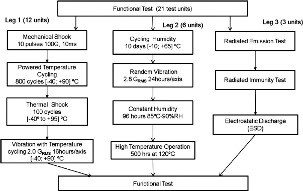
Figure 12.9 Example of a parallel test flow for an electronic device.
It is difficult if not impossible to anticipate all the possible interactions between different test environments and their effects on product failures, therefore past experience and/or a comprehensive design of experiment can provide additional data.
12.6 Failure Reporting, Analysis and Corrective Action Systems (FRACAS)
12.6.1 Failure Reporting
FRACAS is an apt acronym for the task of failure reporting, analysis and corrective action. It is essential that all failures which occur during development testing are carefully reported and investigated. It can be very tempting to categorize a failure as irrelevant, or not likely to cause problems in service, especially when engineers are working to tight schedules and do not want to be delayed by filling in failure reports. However, time and costs will nearly always be saved in the long run if the first occurrence of every failure mode is treated as a problem to be investigated and corrected. Failure modes which affect reliability in service can often be tracked back to incidents during development testing, when no corrective action was taken.
A failure review board should be set up with the task of assessing failures, instigating and monitoring corrective action, and monitoring reliability growth. An important part of the board's task is to ensure that the corrective action is effective in preventing any recurrence of failure. The board should consist of:
- The project reliability engineer.
- The designer.
- Others who might be able to help with the solutions, such as the quality engineer, production or test engineer.
The failure review board should operate as a team which works together to solve problems, not as a forum to argue about blame or to consign failure reports to the ‘random, no action required’ category. Its recommendations should be actioned quickly or reported to the project management if the board cannot decide on immediate action, for example if the solution to the problem requires more resources. This approach has much in common with the quality circles method described in Chapter 15.
US MIL-HDBK-781 provides a good description of failure reporting methods. Since a consistent reporting system should be used throughout the programme MIL-STD-781 can be recommended as the basis for this.
These data should be recorded for each failure:
- Description of failure symptoms, and effect of failure.
- Immediate repair action taken.
- Equipment operating time at failure (e.g. elapsed time indicator reading, mileage).
- Operating conditions.
- Date/time of failure.
- Failure classification (e.g. design, manufacturing, maintenance-induced).
- Report of investigation into failed component and reclassification, if necessary.
- Recommended action to correct failure mode.
- Corrective action follow-up (test results, etc.).
Failure report forms should be designed to allow these data to be included. They should also permit easy input to computer files, by inclusion of suitable coding boxes for use by the people using the forms. An example is given in Appendix 5.
Failure data analysis methods are described in Chapter 13.
12.6.2 Corrective Action Effectiveness
When a change is made to a design or to a process to correct a cause of failure, it is important to repeat the test which generated the failure to ensure that the corrective action is effective. Corrective action sometimes does not work. For example, it can have the effect of transferring the problem to the next weakest item in the sequence of stress-bearing items, or the true underlying cause of failure might be more complex than initial analysis indicates. Therefore re-test is important to ensure that no new problems have been introduced and that the change has the desired effect.
Analysis of test results must take account of the expected effectiveness of corrective action. Unless the causes of a failure are very well understood, and there is total confidence that the corrective action will prevent recurrence, 100% effectiveness should not be assumed.
Questions
- Describe the concept of integrated test planning. What are the main categories of test that should be included in an integrated test programme for a new design, and what are the prime objectives of each category?
- List the important information that should be considered in planning a reliability test programme.
- Identify one major reference standard providing guidance on environmental testing. Identify the major factors to be considered in setting up tests for temperature, vibration, or electromagnetic compatibility.
- Briefly describe the concept of combined environmental reliability testing (CERT). What are the main environmental stresses you may consider in planning a CERT for (i) a domestic dishwasher electronic controller; (ii) a communications satellite electronic module; (iii) an industrial hydraulic pump?
- State your reservations concerning the use of standard environmental test specifications in their application to the equipments in question 4.
- What is ‘accelerated testing’ and what are the main advantages of this type of testing in comparison with non-accelerated tests?
- Explain why the stresses applied in accelerated stress tests should not necessarily simulate expected in-service levels.
- How are tests accelerated for (i) mechanical components under fatigue loading and (ii) electronic systems operating at high temperatures? Comment on the methods used for analysis for the test results for each.
- What is ‘highly accelerated life testing’? Describe the main benefits claimed for this method.
- Why is it important to ensure that all failures experienced during engineering development are reported? Describe the essential features of an effective failure reporting, analysis and corrective action system (FRACAS).
- Give examples of ‘foolish failures’ besides those listed in the chapter. Discuss the ways to avoid these types of failures in testing.
- An electro-dynamic shaker has been set up to vibrate at 12g acceleration level. Compare the peak to peak displacements at 120 Hz and 200 Hz during the sine sweep testing.
- Discuss what happens to the bathtub curve (Figure 12.7) when stress levels approach the design limits. What happens to the bathtub curve pattern when stresses reach the destruct limits?
- You are developing a gear box for a wind turbine power generator for an off-shore installation (sea/ocean water). What kind of environments would you consider including in your test flow? Which tests can be run sequentially and which ones can be done in parallel.
- Would you consider a warranty claims database as FRACAS? What information would warranty return systems have in addition to a typical FRACAS data structure?
- Would the use of HALT be more beneficial in product development of new technological or in evolutionary designs? Justify your answer.
- You are developing a test plan for a temperature cycling test of 300 cycles of [TMIN, TMAX]. How would you take into account the size and the weight of your product when determining the duration of temperature dwells at TMIN and TMAX and the transition time between them?
Bibliography
Environmental Stress Screening Guidelines. Institute of Environmental Sciences and Technology (USA).
GMW 3172 (2004) General Specification for Electrical/Electronic Component Analytical/Development/Validation (A/D/V) Procedures for Conformance to Vehicle Environmental, Reliability, and Performance Requirements, General Motors Worldwide Engineering standard. Available at www.global.ihs.com (Accessed 20 March 2011).
Harris, C., Piersol, A. and Paez, T. (eds) (2010) Shock and Vibration Handbook, 6th edn, McGraw-Hill.
IEC 61 000. Electromagnetic Compatibility.
ISO/IEC 60068. Environmental Testing.
ISO/IEC 61163. Reliability Stress Screening.
McLean, H. (2009) HALT, HASS and HASA Explained: Accelerated Reliability Techniques, American Society for Quality.
O'Connor, P.D.T. (2001) Test Engineering, Wiley.
Steinberg, D. (2000) Vibration Analysis for Electronic Equipment, 3rd edn, Wiley.
UK Defence Standard 07-55. Environmental Testing. HMSO.
US MIL-HDBK-781. Reliability Testing for Engineering Development, Qualification and Production. Available from the National Technical Information Service, Springfield, Virginia.
US MIL-STD-462D. Measurement of Electromagnetic Interference Characteristics. Available from NTIS, Springfield, Virginia.
US MIL-STD-810. Environmental Test Methods. Available from the National Technical Information Service, Springfield, Virginia.