
7.2 System Model
7.2.1 Matrix Converter Model
The power circuit of the MC is presented in Figure 7.1. It uses a set of bidirectional switches to directly connect the three-phase power supply to a three-phase load. This is a 3 × 3 MC. As shown in Figure 7.1, each bidirectional switch is composed of two power transistors with their parallel diodes in anti-series connection.
The MC is connected to the three-phase source through the input filter Lf, Rf, Cf. This filter has two main purposes:
Figure 7.1 Power circuit of the MC
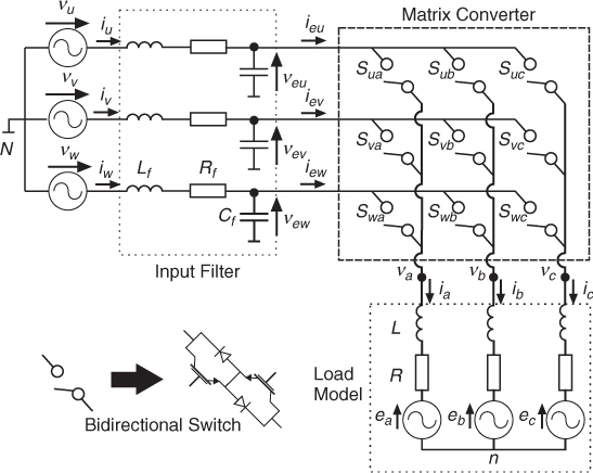
In Figure 7.1 each bidirectional switch is associated with a variable defined as Sxy with x ∈ {u, v, w} and y ∈ {a, b, c}. The conduction state of each bidirectional switch is determined exclusively by the value of its control signal. Sxy is also known as the switching function for switch xy. Sxy = 1 implies that switch xy is on, closed, or conducting, while Sxy = 0 means that the switch is off, open, or in blocking state.
It must be mentioned that the load current must not be interrupted abruptly, because the inductive nature of the load will generate an important overvoltage that can destroy the components. In addition, operation of the switches cannot short-circuit two input lines, because this switching state will originate short-circuit currents. These restrictions can be expressed in mathematical form by the following equation:
Referenced to the neutral point N, the relation between the load and input voltages of the MC is expressed as
where T is the instantaneous transfer matrix.
The input and load voltages can be expressed as vectors as follows:
Using the definitions of (7.3), the relation of the voltages is given by
7.4 ![]()
Applying Kirchhoff's current law to the switches, the following equation can be obtained:
Considering the current vectors
7.6 
the equation for the current is
where TT is the transpose of matrix T.
7.2.2 Working Principle of the Matrix Converter
The bidirectional switches open and close, operating with a high switching frequency, to generate a low-frequency voltage with variable amplitude and frequency. This goal is achieved by generating switching patterns as shown in Figure 7.2. The low-frequency component of the load voltage is synthesized by sampling the input voltages closing and opening the bidirectional switches.
Figure 7.2 Switching patterns for the MC
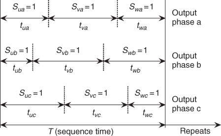
If we define tij as the time during which switch Sij is closed (on) and T is the sampling interval, we can express the low-frequency component of the load voltage as
where ![]() jN(t) is the low-frequency component (mean value calculated over one sampling interval T) of output phase j.
jN(t) is the low-frequency component (mean value calculated over one sampling interval T) of output phase j.
From Figure 7.2 it can observed, for example, that the voltage of phase a is generated by delivering load voltage veu during time tua, voltage vev during time tva, and voltage vwe during time twa.
The conduction times must comply with the restriction
7.9 ![]()
By defining the duty cycles as
and expanding (7.8) for each phase, the following equations can be obtained:
7.11 
7.12 
where ![]() is the low-frequency output voltage vector,
is the low-frequency output voltage vector, ![]() is the instantaneous input voltage vector, and M(t) is the low-frequency transfer matrix of the MC.
is the instantaneous input voltage vector, and M(t) is the low-frequency transfer matrix of the MC.
By considering an analogous procedure for the input currents, it can be demonstrated that
7.14 ![]()
where ![]() is the low-frequency component of the input current vector and MT(t) is the transpose of matrix M(t).
is the low-frequency component of the input current vector and MT(t) is the transpose of matrix M(t).
7.2.3 Commutation of the Switches
The commutation of the current from one bidirectional switch to another is not an easy task, because it is not possible to get exactly the same dynamic behavior when semiconductors are turned on and off. If one switch is turned on too rapidly, it can cause a short circuit at the input of the converter. On the other hand, if the switch is turned on too slowly, the current in the load can be interrupted, generating overvoltages.
This problem has been solved by the introduction of highly intelligent commutation strategies based on current and/or voltage detection, which allow for very safe commutation. These methods will not be described in this book but can be found in [1].