
7.3 Classical Control: The Venturini Method
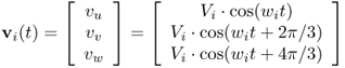
The sinusoidal voltages of the three-phase power supply can be expressed as
The desired voltages generated at the load, which are the low-frequency components, can be expressed as
7.16 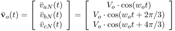
Neglecting the presence of the input filter, the relation between the amplitude of the input voltage and the amplitude of the output voltage is
7.17 ![]()
where q is the voltage gain.
Considering that the typical load of a MC will have low-pass characteristics, the output current is
7.18 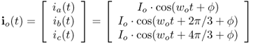
To operate with unity power factor, the switches must be controlled to generate the following input currents (the fundamental components):
7.19 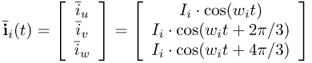
The MC does not store energy and, for this reason, the active power at the input (Pi) and at the output (Po) must be equal at all times, as expressed by the equation
With all these fundamental definitions, the task of the modulator is to find a low-frequency transfer matrix M(t) such that (7.13) and (7.7) are satisfied, considering the restrictions given by (7.15)–(7.20).
The solution for the matrix M(t) can be obtained from [1] and [3] and can be reduced to a very compact expression given by
where i ∈ {u, v, w} and j ∈ {a, b, c}.
The procedure for modulation of the MC can be resumed in the following steps:
Figure 7.3 shows the operation of the MC controlled by the Venturini method. It can be observed that voltage vaN is synthesized using all three phases of the grid. The load current ia is very sinusoidal, with a small ripple that can be reduced even more by increasing the switching frequency.
Figure 7.3 Output voltage vaN and output current ia generated by the Venturini method
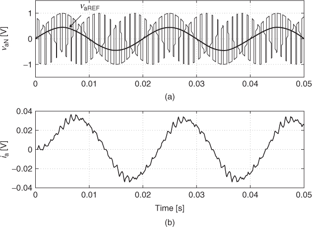
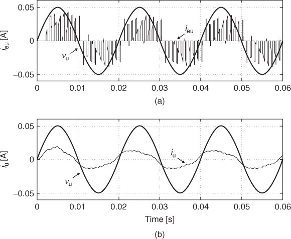
Figure 7.4 presents the input voltage vu and the input currents. It can be observed that the input current ieu has strong commutation and that these abrupt changes are completely eliminated from iu as a result of the filter action.
Figure 7.4 Input voltage and currents generated by the Venturini method
Space vector modulation can also be applied in MC. This technique will not be included in this book but more information about it can be found in [1] and [4].