
8.4 Predictive Torque Control of an Induction Machine Fed by a Voltage Source Inverter
For an induction machine, it can be demonstrated that both the stator flux ![]() and electromagnetic torque T can be modified by selecting a proper voltage vector sequence that modifies the magnitude of the stator flux and at the same time increases or decreases the angle between the rotor and stator flux. These ideas correspond to the basics of direct torque control.
and electromagnetic torque T can be modified by selecting a proper voltage vector sequence that modifies the magnitude of the stator flux and at the same time increases or decreases the angle between the rotor and stator flux. These ideas correspond to the basics of direct torque control.
In predictive torque control (PTC), the same principle is used, but in this scheme predictions for the future values of the stator flux and torque are calculated. Hence, the reference condition, which is implemented by a cost function, considers the future behavior of these variables. Predictions are calculated for every actuating possibility and the cost function selects the voltage vector that optimizes the reference tracking. A block diagram of PTC is shown in Figure 8.5.
Figure 8.5 PTC scheme
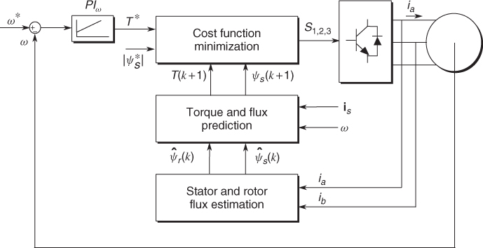
The block concerning estimation is used to calculate the current values of the variables that cannot be measured, such as the rotor flux ![]() and the stator flux
and the stator flux ![]() . Then, the predictive model computes the future values of controlled variables at the instant k + 1, in this case the stator flux
. Then, the predictive model computes the future values of controlled variables at the instant k + 1, in this case the stator flux ![]() and the electromagnetic torque T(k + 1). These predictions are calculated for every actuating possibility given by the inverter topology. If a two-level inverter is considered, eight switching states and seven different voltage vectors can be generated. Finally, the block concerning minimization chooses the optimum switching state which minimizes the corresponding cost function. This function contains the control law in order to achieve an appropriate torque and flux regulation.
and the electromagnetic torque T(k + 1). These predictions are calculated for every actuating possibility given by the inverter topology. If a two-level inverter is considered, eight switching states and seven different voltage vectors can be generated. Finally, the block concerning minimization chooses the optimum switching state which minimizes the corresponding cost function. This function contains the control law in order to achieve an appropriate torque and flux regulation.
In PTC, estimations of the stator flux ![]() and the rotor flux
and the rotor flux ![]() , at the present sampling step, are required.
, at the present sampling step, are required.
The stator flux estimation is based on the stator voltage equation:
Using the Euler formula to discretize (8.17), the stator flux estimation is obtained:
The rotor flux estimation ![]() is obtained from the flux linkage equations, by replacing the rotor current ir obtained from (8.19) in (8.20):
is obtained from the flux linkage equations, by replacing the rotor current ir obtained from (8.19) in (8.20):
Thus, by discretizing (8.21) and replacing the current estimation for the stator flux ![]() , the rotor flux estimation
, the rotor flux estimation ![]() is obtained:
is obtained:
After the rotor and stator flux estimations have been obtained, it is necessary to compute the predictions for the controlled variables. In the case of PTC, the electromagnetic torque T and the stator flux ![]() are predicted for the next sampling instant k + 1.
are predicted for the next sampling instant k + 1.
For the stator flux prediction ![]() , the same stator voltage equation used for its estimation is considered. By approximating the stator flux derivative, the prediction for the stator flux is obtained:
, the same stator voltage equation used for its estimation is considered. By approximating the stator flux derivative, the prediction for the stator flux is obtained:
8.23 ![]()
The torque prediction depends directly on the stator flux and current according to
8.24 ![]()
Thus, by considering the predicted values of the stator flux and stator current, the torque prediction is obtained:
As observed in (8.25), a prediction of the stator current ![]() is needed to compute a prediction for the electromagnetic torque.
is needed to compute a prediction for the electromagnetic torque.
Discretizing (8.14), and replacing the derivatives by the Euler-based approximation, it is possible to obtain a prediction for the stator current is at the time k + 1:
8.26 ![]()
Once the predictions of the stator flux and stator current have been obtained, it is possible to calculate the prediction of the electromagnetic torque.
Both the torque and stator flux predictions are written in terms of the inverter voltage vs(k). This implies that seven different predictions for the torque and the flux ![]() , h ∈ [0, 1, … , 6], are obtained according to the number of voltage vectors generated by a two-level inverter.
, h ∈ [0, 1, … , 6], are obtained according to the number of voltage vectors generated by a two-level inverter.
Finally, the switching state selection is made by means of a cost function which contains the control law. Basically, it corresponds to a comparison between the torque and flux references to their predicted values. The cost function is evaluated for every prediction and the one that produces the lowest value is selected. Thus, the firing pulses of the inverter are generated.
The cost function has the following structure:
8.27 ![]()
The term λψ denotes the weighting factor, which increases or decreases the relative importance of the torque versus the flux control. This is the only parameter to be adjusted in PTC. If the same weight were assigned for both control variables, these factors would correspond to the ratio between the magnitudes of the nominal torque Tn and stator flux ![]() :
:
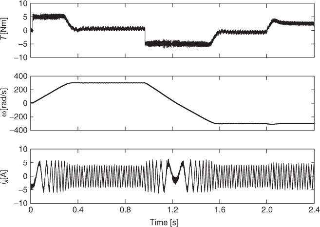
A dynamic result can be seen in Figure 8.6. The maneuver corresponds to controlled starting, a speed reversal, and a load torque response. It is possible to see that PTC achieves an excellent dynamic performance with low distortion of the stator currents and torque.
Figure 8.6 Starting, speed reversal, and load torque using PTC
A torque step response is shown in Figure 8.7a. It is important to point out the fast dynamic behavior of the strategy. This can be explained by the fact that PTC is a direct strategy that does not require an inner PI control loop for the stator currents and modulators. Hence, there is no bandwidth limitation for the electromagnetic torque dynamics.
Figure 8.7 Torque step response and steady state behavior of the stator current. (a) Torque step response. (b) Stator current
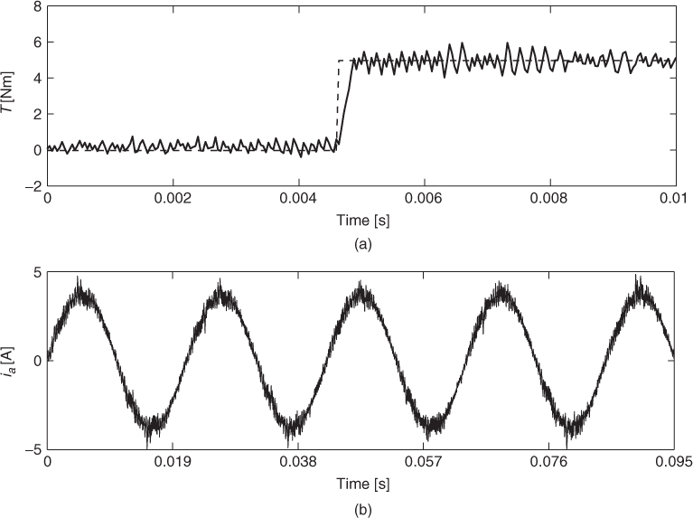
The behavior of the stator currents at steady state operation is presented in Figure 8.7b. In this condition the machine is operating at the rated speed (![]() ) at an equivalent load of 50% of the nominal torque. Note that low harmonic distortion can be achieved. The resulting THD is equal to 4%.
) at an equivalent load of 50% of the nominal torque. Note that low harmonic distortion can be achieved. The resulting THD is equal to 4%.