The Digi 002 and the Command | 8
The Digi 002
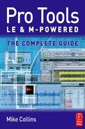
Resembling a typical small digital mixer, the Digi 002 actually combines the features of a high-quality audio interface, a MIDI interface, a touch-sensitive control surface, and a stand-alone digital mixer, all in one unit. Connecting to your computer through a single FireWire connection, Digi 002 pairs Pro Tools LE software with a dedicated control surface for hands-on control of the software.
Audio and MIDI data are passed back and forth between your computer and the Digi 002 via the FireWire cable along with control information generated by or returned to the Digi 002 control surface. Any moves you make using the Pro Tools software on the computer screen will be reflected on the control surface – and vice versa.
At the push of a button, the Digi 002 unit can be switched into Standalone mode to become an 8 × 2 digital mixer, complete with two internal and two external effects sends, EQ, dynamics, effects, reverb, and automation snapshots. So you can use Pro Tools LE with the Digi 002 to record, edit, process, mix, and master your projects in your home studio, then put the Digi 002 under your arm, take it to a gig, and use it as a digital mixer on-stage. Whoopee! It’s your flexible friend!
The Digi 002 lies somewhere in that grey area between an entry-level product and a professional product that is sometimes referred to as ‘prosumer’. It is definitely going to give you better audio quality than an Mbox, for example, but it is not quite in the same league as Digidesign’s HD systems which offer much higher-quality converters and analogue electronics and much more choice when it comes to building systems with many inputs and outputs.
Nevertheless, the Digi 002’s analogue inputs and outputs support the most important sample rates that you are likely to encounter, with A/D and D/A converters allowing sample rates of 44.1, 48, 88.2, or 96 kHz. The coaxial S/PDIF connectors support up to 24-bit, 96 kHz audio. If you use the optical connectors in ADAT mode then these can only support the original 44.1 and 48 kHz sample rates that they were designed for. But if you use these in Optical S/PDIF mode they will also support the higher sample rates of 88.2 and 96 kHz.
tip
Don’t forget to select the appropriate I/O format as the Clock Source in the Hardware Setup dialog when transferring material digitally into Pro Tools using ADAT or S/PDIF formats.
Rear panel
As you might expect, the Digi 002 has similar connectors on its rear panel to those on the Digi 002R.
At the lower right-hand side, there are four Microphone Inputs via balanced, three-conductor XLR connectors. If you are using condenser microphones that need to take their power from the microphone cables, you can switch on the 48-volt so-called ‘phantom’ power for inputs 1 and 2 or for inputs 3 and 4 using two small push-button switches located above. This 48-volt power is then supplied to the microphone via its own cable.
Also located above the microphone inputs, there are four Line/Instrument inputs that use balanced, 1/4″ TRS jacks for line-level or instrument-level inputs. These line inputs have operating levels fixed at +4 dBu, which means that they are suitable for connection to professional audio equipment. To the left of these there are four more analogue inputs that also use balanced, 1/4″ TRS jacks for line-level inputs. The operating levels of each of these inputs can be set to either +4 dBu or to −10 dBV to suit consumer audio equipment, using switches immediately to the right of the input jacks.
note
A –10 dBV input pair marked ‘Alternative Source’ is provided using RCA connectors so that you can hook up a tape, cassette or CD player for playback.
The Digi 002 also has eight analogue audio outputs. The Main (1–2) Output pair can be connected to a professional tape or DAT machine or other equipment at +4 dBu operating level using balanced, 1/4″ TRS jacks.
Analog Outputs 3–8 also use balanced, 1/4″ TRS jacks at a fixed +4 dBu operating level – so these are intended for connection to professional audio equipment such as analogue signal processors (compressors, EQ’s, reverbs, and other effects) or to headphone distribution amplifiers for musicians to use.
The Monitor Output pair mirrors the Main (1–2) Output pair and works together with its front-panel volume control to provide direct connection to a monitor amplifier or to professional powered speakers at a fixed +4 dBu operating level.
A −10 dBV ‘Alternative Main’ unbalanced output pair that mirrors the Main (1–2) Outputs can be used to provide a direct connection to −10 dBV devices such as consumer-quality cassette players or to a consumer hi-fi amplifier or powered speakers if you don’t have professional monitoring equipment.
At the lower left-hand side you will find a pair of optical connectors for eight channels of ADAT I/O or two channels of Optical S/PDIF I/O; a pair of RCA connectors for two channels of S/PDIF digital I/O; and two FireWire ports – one to connect to your computer and one to let you daisy-chain other FireWire devices such as digital cameras or camcorders.
To the left of these, there is a footswitch jack that you can use to punch in and out of record. To the right there are three five-pin DIN MIDI sockets – one MIDI In, and two MIDI Outs – allowing for 16 channels of MIDI input and 32 channels of MIDI output.
Finally, the power connector will accept AC supplies between 100 and 240 volts running at either 50 or 60 Hz – so you can connect the Digi 002 to the main electricity supplies in most countries around the world without problems.
The control surface
The Digi 002 control surface is divided into two main sections with the input gain and output level controls at the top and the other controls below.
The main section is further sub-divided to group the control knobs, more switches and the ‘scribble strip’ displays in the middle section with the moving faders below these in the lowest section and the transport controls to the right of these.
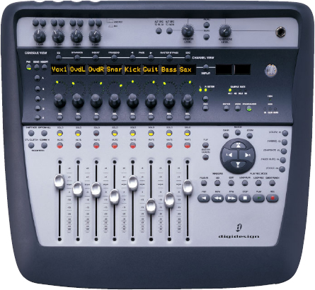
Fig. 2.1 – Digi 002 control surface.
Top section
Let’s look at the top section first. At the top left there are four rotary gain controls for the four microphone preamplifiers. Above these there are four pairs of buttons. The first of each pair switches the input between microphone and line level. The second button switches in a high-pass filter. This filter removes the lower frequencies that may contain rumble or other unwanted sounds.
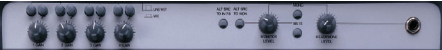
Fig. 2.2 – Digi 002 top section.
To the right of these there are two small button switches. The first of these routes the Alternative Source to input pair 7–8. The second routes the Alternative Source to the monitor outputs. An associated rotary control knob lets you adjust the output level to the monitors, and adjacent to this a button switch is provided to let you mute the monitors. There is also a Mono button that can be very useful when checking audio that will be broadcast (which may be in mono).
Finally, at the far right of the panel, there is a 1/4″ jack socket for headphone output with an associated volume control knob.
Middle section
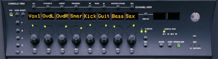
Fig. 2.3 – Digi 002 middle section.
Home view
The Digi 002’s default view is called the Home View. The idea here is that you should always go back to this ‘home’ view after going outside the ‘home’ view to other views.
Home view is the Console View with the Pan controls displayed on the rotary encoders and the mixer channel names shown in the Channel Scribble Strips. This makes sense as the default view because the faders control volume and the rotary encoders control pan and both of these are positioned on the control surface just where you would expect volume faders and pan controls to be on a mixer.
Console View Selectors
In the middle section, there is a row of three buttons at the far left to let you select the Console View. You can use these to choose whether to view the pans, sends or inserts in the ‘Scribble Strips’ located to the right of these.
The default setting is the Pan View in which, when you first launch a Pro Tools session, the faders control track volume and the rotary encoders control channel pan positions.
When you switch to Send View, the Channel Scribble Strips show the names of any currently assigned sends and the rotary encoders are assigned to control the send levels.
When you switch to Insert View, the names of any plug-ins currently assigned as inserts (whether hardware inserts or plug-ins) will appear in the corresponding Channel Scribble Strips. If you select any of these inserts in the Pro Tools Mix or Edit windows, its name will flash on and off in the Scribble Strip so that you know where it is. Select the one you are interested in by pressing the corresponding Channel Select button on the Digi 002 and the controls will be shown in the Channel Scribble Strips and assigned to the rotary encoders ready for you to adjust.
Insert/Send Position Selectors
Pro Tools has ten sends and five inserts available for each channel so the Digi 002 needs a way to switch its displays between these. At the far left of the middle section, underneath the Console View Selectors, you will find a vertical column of buttons labelled A to E. These are the Insert/Send Position Selectors and they are there to let you choose which of the available send or insert positions are displayed in Console View.
Channel Scribble Strips
The eight Channel Scribble Strips display channel information such as track name, or pan, send, or plug-in values. They can also display the fader values in Decibels (dB’s).
When you move a fader or a rotary encoder, the scribble strip will temporarily display the value for that control before returning to the default display. So with the pan values showing in the scribble strips, if you move a fader, it will show the fader value while you are moving the fader and for a fraction of a second after you let go of the fader – then it will revert to showing the pan value.
Display Scribble Strips and Display Mode Switch
To the right of the Channel Scribble Strips, two more ‘scribble strips’ show additional information – the Display Scribble Strips.
For example, if you have any stereo tracks in your Pro Tools Session, the Channel Scribble Strips will default to displaying the pan values for the left channels. To view and be able to modify the right channel pan settings, you have to press the button marked ‘L R Meter’ located to the right of the encoder displays. Three associated LEDs indicate whether you have selected the left or right channels for panning, or the left or right Meter. This information is also shown in the Display Scribble Strips.
By default, the Display Scribble Strips always show the current status of the Channel Scribble Strips. So, for example, if you hit the Insert View button, it will say which insert you are viewing, such as Insert A.
If you press the Command switch at the same time as the Display Mode switch, the channels will display numerical parameter values rather than control names. For example, in Pan view, when you press Command + Display, fader volume levels in dB are shown as the default display.
You can also show the Pro Tools main Counter in the Display Scribble Strips by pressing the Display Mode switch, which is located right between the Display Scribble Strips and the Channel Scribble Strips. So you can see the Bar:Beat location or the Society of Motion Picture and Television Engineers (SMPTE) location or whatever the main Counter is set to.
More buttons and status indicators
There are various LEDs and buttons located below the Display Scribble Strips. Four LEDs indicate the sampling rate: 44.1, 48, 88.2, or 96 kHz.
Three buttons underneath these let you select Enter, Undo, and the Standalone mode.
Three more LEDs to the right of these indicate MIDI input and output activity.
To the left you will find the Record Enable button. When this is pressed you can arm any track for record by pressing its Channel Select button on the Digi 002.
Rotary encoders
Underneath the Channel Scribble Strips you will find eight rotary encoders that you can use to adjust the pan, send, meter, and plug-in channel settings. Each rotary encoder has a circle of 15 LEDs above it to indicate data values controlled by the encoder.
The style of display depends on the type of data. For example, discrete or stepped information such as pan position or frequency value is shown by a single LED, while an expanding series of LEDs shows values such as send levels, gain, or filter bandwidth. The LED rings can also be set to show track levels by pressing the Encoder/Meter mode switch to the right of the encoder area (the button marked ‘L R Meter’). When you set this to Meter mode, the LED rings show increasing levels in a clockwise manner. When the last red LED lights, this indicates clipping.
Channel Select
Underneath the rotary encoders you will find a row of eight Channel Select button switches.
In Pan view, pressing a Channel Select switch selects the corresponding track in Pro Tools – which is what you would expect it to do.
In Send View, the Channel Select switch toggles the selected send on that track between pre- and post-fader operation – which is a useful function in this view.
In Insert View, pressing a Channel Select switch directly under a plug-in name does something much more radical: it puts Digi 002 into Channel View and displays the plug-in controls across all the channel strips.
Channel View
Above the Channel Scribble Strips there is a row of eight buttons. The first four of these are the Channel View Selectors that let you choose between viewing the EQ, Dynamics, Insert, or Pan/Send settings.
There are two Page buttons to let you page forward or backward when you are using plug-ins with more controls than will fit on the eight scribble strips. There is also a Master Bypass button that works with the currently selected plug-in or with all plug-ins on a channel, depending on the current view. Finally, there is an Escape button that lets you cancel certain operations, such as the Channel View selections. It also functions as a ‘Cancel’ button for on-screen dialogs in Pro Tools.
Channel View lets you zoom in on a single track and display all the plug-in assignments, insert names, or send assignments horizontally, across all the Channel Scribble Strips. From this view, you can recall and edit parameters for all the sends on a single track, or all the parameters of a single plug-in.
In Channel View, the LED rings above the rotary encoders indicate values for the selected control showing plug-in parameters, send levels, insert levels, or pan values depending on which Channel View switch is lit.
Don’t forget that, just as in Console View, the Digi 002’s faders mirror the Pro Tools software’s volume faders when in Channel View.
note
Dedicated buttons for EQ and Dynamics are provided because these are used so often. Any plug-ins can be accessed using the Insert button (including EQ and Dynamics) but it is more efficient to use the dedicated buttons for EQ and Dynamics if these are what you want to get to.
tip
To cycle through all the plug-ins or inserts on a channel, hold the EQ, Dynamics or Insert button and repeatedly press the track’s Channel Select switch.
note
On Digi 002 (and Command |8), when you use Channel View to display the sends on a single Pro Tools channel, you can only view Sends A–E. To view Sends F–J, use Console View. Press the Send switch to put Digi 002 (or Command |8) into Sends View, then hold the Shift/Add switch and press the corresponding Send Position switch (A = F, B = G, C = H, D = I, E = J).
EQ When you press the EQ switch, the Channel Select buttons will light up on any channels that have an EQ plug-in inserted so that you can identify these. Choose the one you want to work with by pressing its Channel Select button.
Controls for the first EQ plug-in on that track are then assigned to the rotary encoders and displayed in the Channel Scribble Strips and switched controls, such as Master Bypass or Phase Invert functions, can be controlled using the Channel Select switches.
If you have more than one EQ plug-in inserted on a track, you can get to the second by holding the EQ button and pressing the track’s Channel Select button. The controls will then be displayed on the Channel Scribble Strips, and if the first EQ plug-in’s window is open in Pro Tools, the window will switch to the second EQ plug-in.
Dynamics When you press the Dynamics switch, the Channel Select buttons will light up on any channels that have dynamics plug-ins (such as compressors or limiters) inserted so that you can identify these.
Choose the one you want to work with by pressing its Channel Select button. Controls for the first Dynamics plug-in on that track are assigned to the rotary encoders and displayed in the Channel Scribble Strips. Switched controls, such as Phase Invert or In/Out for EQ bands, can be controlled using the Channel Select switches below the corresponding Scribble Strips. Again, if you have more than one Dynamics plug-in inserted on a track, you can get to the second by holding the Dynamics button and pressing the track’s Channel Select button.
Inserts When you press the Inserts switch, the Channel Scribble Strips will show abbreviated names for any inserts on the track and the Channel Select buttons will light up on any channels that have a plug-in (or any hardware I/O) inserted so that you can identify these.
You should check the Display Scribble Strips at this point to see which of the five insert slots you are viewing in the Channel Scribble Strips. These are labelled A to E and you can select which to view using the Insert/Send Position Selectors at the middle left of the control surface.
You can choose which insert to edit by viewing each of the five insert slots in turn until you find the insert you are looking for, then pressing the corresponding illuminated Channel Select button.
When you press the Pan/Send switch, Digi 002 identifies channels with sends assigned to them by illuminating their Channel Select switches. If no sends are present, no Channel Select switches will be lit. If you do have any sends in your Pro Tools Session, you can access the controls for any of these by pressing the corresponding illuminated Channel Select switch.
Channel Scribble Strip 1 and the first rotary encoder show track pan position for that track. (If the track is a stereo track, you can toggle between left and right pan by pressing the Encoder Mode switch immediately to the right of the encoders. This switch is marked ‘L R Meter’ on the Digi 002.)
Channel Scribble Strips 3–7 show the names and their rotary encoders control the levels for the first five sends on that track. (Channel Scribble Strip 2 is inactive.) In this mode, the Channel Select switches on channels 3–7 toggle pre- and post-fader metering for the corresponding send.
Multi-mono plug-ins
When working with a multi-mono plug-in, you can toggle the view between the left and right sides of the plug-in by holding down the Display Switch when you press the Channel Select switch to select a plug-in from Channel view.
The resulting display shows ‘left’ and ‘right’ in the Scribble Strips, allowing you to choose between the two sides of the multi-mono plug-in by pressing the corresponding Channel Select switch.
Lower section
The lower section contains the faders along with the transport and navigation controls.
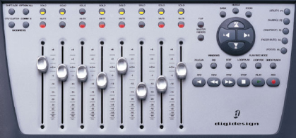
Fig. 2.4 – Digi 002 lower section.
Faders
The fader section consists of eight identical channel strips, each with a touch-sensitive motorized fader, solo and mute switches.
Transport controls
Located to the right of the fader section there is a group of transport control buttons: Play, Record, Stop, Fast Forward, Rewind, and Return to Zero.
Navigation & zoom
Above the transport controls there is a raised circular controller containing left/right and up/down navigation keys.
Above this controller there are three button switches that you can use to define the function of the left/right arrow.
Use the Bank switch to swap the Pro Tools tracks that are displayed on the Digi 002 for the next bank of eight or the previous bank of eight. If you want to move the tracks one at a time, use the Nudge switch instead.
If you press the Zoom button, you can also use the controller to control the zoom function in the Pro Tools Edit window. When this button is lit, the Left and Right arrow keys zoom the display horizontally and the up and down arrow keys zoom the display vertically in and out.
The Left and Right arrow keys can also be used to navigate between editable fields when you are editing numerical values such as Selection Start, End, and Length or Pre-and Post-Roll in the Edit or Transport windows. The Up and Down keys can be used to increment or decrement the selected value.
In Bank and Nudge modes, the Navigation keys perform the same function as the Up or Down keys on the computer keyboard. So you can use these keys to mark in and out points during playback to make selections in the Pro Tools Edit window. If you have already made a selection in the Edit window, the Up and Down keys will move the selection up and down your track list.
Window show/hide and Playback Mode switches
In between the navigation controller and the transport controls there are six more control buttons. The first, marked ‘Plug-in’, opens or closes the window of the currently selected plug-in The second, marked ‘Mix’, opens, brings forward, or closes the Mix window in Pro Tools and the third, marked ‘Edit’ does the same for the Edit window. The next three buttons let you switch the various Play/Record modes on or off: Loop Playback, Loop Record, and QuickPunch.
Fader Flip & Master Faders
To the left of the navigation controller there are two buttons, marked ‘Flip’ and ‘Master Faders’.
The Fader Flip switch transfers control assignments from the rotary encoders to the corresponding channel faders, allowing you to use the touch-sensitive faders to edit and automate these control values. So, for example, if you hit the Flip button in Console View, it will move the send level controls to the channel faders and the send pan controls to the rotary encoders. Or in Channel View, if you are working with a plug-in insert, pressing the Flip button will move the plug-in’s controls from the rotary encoders to the faders.
Pressing the Master Fader switch arranges any and all of the Master Fader tracks in the current session on the right-hand side of the control surface so that you can focus on making adjustments to these. Pressing this switch a second time returns the control surface to the previous view.
Function/utility keys
To the right of the navigation controller, there are five function keys labelled F1 to F5. F1 takes you into Utility Mode when the Digi 002 is in stand-alone mode so that you can set the control surface and input preferences and run diagnostic tests. Also for use in stand-alone mode, F2 lets you name channels and F3 lets you store and recall up to 24 mixer configurations.
F4 temporarily prevents the faders from moving while you are working with Pro Tools so that you can listen to your audio playback without hearing the noise of the faders moving on the Digi 002. When you want the faders to move again, just press F4 a second time. Don’t worry about this affecting the sound in Pro Tools though: this feature stops the Digi 002 faders from moving but it doesn’t affect the virtual faders in the Pro Tools Mix window (these will continue to move).
F5 is a short cut that lets you display the currently active plug-in’s controls in the Digi 002 Channel Scribble Strips. Using this is much faster than pressing the Insert button to enter Channel View then pressing the channel select button for the plug-in you want to make active and again to display its controls in the Scribble Strips. And when you have adjusted the controls, another press on the F5 button takes you back to the view that you were in previously.
Keyboard modifier switches
To the left of the fader section there are four modifier keys corresponding to the modifier keys on your computer keyboard. These are labelled the same way as the modifier keys on Apple computers, so you have Shift, Option, Control, and Command. You can use these in the same way as those on the computer keyboard in combination with other key presses on the computer keyboard or with mouse clicks.
The Shift/Add Switch allows you to extend a track selection or add to a group of selected items. The Option/All Switch applies an action or command to all the tracks in a Pro Tools session. So, for example, this is very useful if you want to insert an EQ plug-in onto every track: just hold the Option key while you are inserting the plug-in onto the first track and it will insert it onto every track of the same type. The Control/Clutch Switch temporarily stops a control from acting as part of a group of controls. If you need finer adjustment of any Pro Tools controls or automation breakpoints, simply hold down the Command Switch while you adjust these and small increments will become possible.
Digi 002 modes
The Digi 002 goes into Standby mode when you power it up and it waits in this mode until you either launch Pro Tools LE or switch to Standalone mode. When the Digi 002 is connected to a computer with Pro Tools LE software running, it goes into Pro Tools mode.
The Digi 002 can also be used as a stand-alone eight-channel digital audio mixer – with or without being connected to the computer. You can switch to Standalone mode either from Standby mode or from Pro Tools mode and your computer is no longer needed for Digi 002 to operate.
Standalone Mode
To put the Digi 002 into Standalone mode just press the Standalone switch on the right-hand side of the Digi 002 top panel and confirm that you want to enter Standalone mode by pressing the Channel Select switch that is flashing under the word ‘Yes’. To exit Standalone mode, simply press the Standalone switch a second time. Digi 002 goes into Standby mode, or re-enters Pro Tools mode automatically if Pro Tools software is still running.
In Standalone mode, the Digi 002 has dedicated, in-line three-band EQ on input channels 1–8 and dedicated, in-line compressors on input channels 1–4. There are four sends available on each channel for adding internal Delay or Reverb effects, or for hooking up external effects processors. Sends 1–2 are dedicated to the internal Delay and Reverb effects. Sends 3–4 route the input signals out via outputs 7–8 on the back panel so you can send to external effects.
The ten ‘Scribble Strips’ display the pan, volume and effects controls, send levels, and track names. The LED Encoder rings on each channel strip show the pan positions in Pan View and Master Fader view but show send levels or other information in other views. If you press the button marked ‘L R Meter’ this puts the Digi 002 into Meter mode so that the LED rings act as post-fader meters unless you are viewing the compressor controls, in which case they act as input, output, and gain reduction meters for the displayed compressor.
Hooking up external sources to the Digi 002 in Standalone mode
Inputs 1–4 accept microphone-, line-, or instrument-level signals and you can adjust the input gains for these using the controls located at the left of the Digi 002’s top panel. Inputs 5–8 only accept line-level signals and are switchable between −10 dBV and +4 dBu using the operating level switches on the Digi 002 back panel.
The Alt Src Inputs can be used to hook up alternative audio sources such as CD players or tape decks. These can either be routed directly to the Monitor and Headphone outputs by pressing the Alt Src to Mon switch or they can be routed to Input channels 7–8 by pressing the Alt Src to 7–8 switch (in which case inputs 7–8 on the back panel of the Digi 002 are disabled).
If you have a DAT or CD player with S/PDIF digital outputs you can route these via the Digi 002’s S/PDIF digital connector to inputs 5–6, allowing you to bring a stereo digital signal into the Digi 002. When playing audio into the Digi 002 digitally, you will need to change the sync mode settings to S/PDIF.
tip
Some digital audio equipment (and even some personal computers such as the Mac G5) features Optical S/PDIF inputs and outputs that you can connect directly to the Digi 002. This can be useful when you want to play iTunes back through your main monitors, or to set up iChat on your Mac for video conferencing over the Internet using your main monitors instead of the Mac’s internal speakers. Don’t forget to set the sync mode to Word Clock, set the S/PDIF inputs to Optical, and set up the routing for the S/PDIF inputs to Digi 002 inputs 5–6 first. You can access these settings in Standalone mode by pressing the F1 Utility button, choosing Preferences by pressing the corresponding Channel Select button, and pressing the appropriate Channel Select buttons to access the desired settings.
In Standalone mode, all eight Input channels, the Delay return, and the Reverb return are summed to outputs 1–2, which are routed to the Main Outputs, to the Alt Main Outputs, and to the S/PDIF outputs on the back panel of the Digi 002. Outputs 1–2 are also mirrored on the Monitor Outputs and Headphone Output.
note
If Optical is chosen in the S/PDIF preferences, only Main Outputs 1–2 are mirrored in the Optical Output port. If RCA is chosen in the S/PDIF preferences, all eight Input channels are passed directly to the eight ADAT Optical Outputs, pre-fader, pre-effects, except for the high-pass filter on channels 1–4. This allows you to route input signals directly to an ADAT device without repatching cables.
Digidesign Command | 8 Control Surface
It can be very useful to have a hardware control surface to use with Pro Tools – especially if you do not have an audio mixer. The Command | 8 is similar to the Digi 002 – but without the audio interface features. It is primarily a control surface – although it does have basic monitoring and routing facilities.
note
You can use the Command |8 to provide extra faders with a Digi 002 and it can also be used for remote control of play and record functions with Digidesign’s ProControl and Control |24 professional control surfaces.
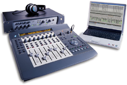
Fig. 2.5 – Digidesign Command | 8 control surface with 002R interface and laptop.
Designed specifically for use with Pro Tools, the Command | 8 Control Surface has a big, bright 110-character backlit LCD display that is at least twice as nice as the Digi 002’s display and connects to your computer using a standard USB cable. It has eight sets of touch-sensitive moving faders and rotary encoders that you can easily shift in banks to control all of the tracks in your Pro Tools session.
The Command | 8 gives you full control of all the channel strip functions in Pro Tools, allowing you to view and edit plug-in parameters and automate all the sends, pans, track volume, and mutes. Transport controls are also included, along with a footswitch jack that can be used to punch into record.
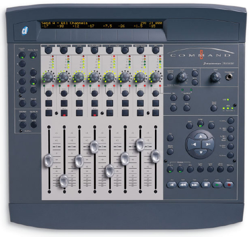
Fig. 2.6 – Command | 8 top showing details of controls.
The Command | 8 also has one MIDI In and two MIDI Out sockets and can work as a MIDI controller with any third-party MIDI software and devices that will allow you to map MIDI control change messages for level, panning, solo, mute, MIDI Machine Control, and other parameters to Command | 8 controls.
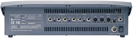
Fig. 2.7 – Command | 8 back.
You can connect the analogue audio stereo mix outputs from an Mbox, Digi 002 Rack or any of the M-Powered interfaces to the Command |8’s Main Monitor inputs and route this audio via the Command | 8’s Speaker Outputs to a pair of powered monitors for control room monitoring.
A pair of External Source inputs lets you hook up another stereo source such as a CD player. The inputs and outputs all use balanced 1/4″ TRS jacks and are individually switchable between −10 dBV and +4 dBu operating levels. A switch is provided to let you choose between Main and External input sources, along with control room Level, Mono and Mute switches. A Headphone output is also provided with its own separate level control.