
Day 2 Walking in Circles
The Plan
It is funny how many stories of expeditions gone wrong culminate with a revealing moment where the explorers realize they got desperately lost and have been walking in circles for a while. In embedded-control programming it’s the opposite: Our programs need a framework, a structure so that the flow of code can be managed, and this usually is built around one main loop.
Today we will review the basics of the loops syntax in C, and we’ll also take the opportunity to introduce a first peripheral module: the 16-bit Timer1. Two new MPLAB© SIM features will be used for the first time: the Animate mode and the Logic Analyzer view.
Preparation
For this second lesson, we will need the same basic software components we installed (from the attached CD-ROM and/or the latest versions available for download from Microchip’s Web site) and used before, including:
We will also reuse the New Project Setup checklist to create a new project with the MPLAB IDE.
Select the Project Wizard from the Project menu and proceed through the few steps that follow:
shortcut, or clicking the corresponding ![]() (New File) button in MPLAB standard toolbar.
(New File) button in MPLAB standard toolbar.

Soon, after you repeat these same steps a few more times, they will become automatic to you, but you will always have the option to refer to the Create New File and Add to Project checklists conveniently included in this book.
The Exploration
One of the key questions that might have come to mind after you worked through the previous lesson is, “What happens when all the code in the main() function has been executed?” Well, nothing really happens, literally!
When the main() function terminates and returns back to the startup code (crt0), a new function _exit() is called and the PIC32 remains stuck there in a tight loop from which it can escape only if a processor reset is performed. Notice that this is something that depends on the MPLAB C32 tool suite and that is not a C language proper feature. C compilers normally are designed to return control to an operating system when the main() function returns, but as you understand, there is no operating system to return to in our case.
Note
The _exit() function, just like the startup code, is not visible in the editor window (not our code) and is not visible even from the disassembly window (not a library). The only way you can find out about it is if you open the Memory window and you select the Code View pane.
The good news is that we can easily define a replacement for the _exit() function if we have a better idea of what to do with it. We could, for example, mimic what the MPLAB C30 tool suite used to do for PIC24 and dsPIC applications—that is, insert a reset instruction in there and have the entire application repeat over and over again. But what we truly want in embedded control is an application that runs continuously, from the moment the power switch has been flipped on until the moment it is turned off. So, letting the program run through entirely, reset, and execute again might seem like a convenient way to arrange the application so that it keeps repeating as long as there is “juice.”
The reset option might work in a few limited cases, but what you will soon discover is that running in this “loop,” you develop a “limp.” Upon reaching the end of the program, executing the reset instruction takes the microcontroller back to the reset vector to again execute the startup code. As short as the startup can be, it will make the loop very unbalanced. Going through all the SFR and global variable initializations each time is probably not necessary and it will certainly slow down the application. A better option, instead, is to code a proper application main loop ourselves. To begin, let’s review the most basic control flow mechanisms available in C language.
While Loops
In C there are at least three ways to code a loop. Here is the first: the while loop:
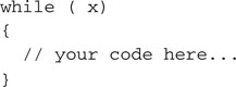
Anything you put in between those two curly brackets {} will be repeated for as long as the logic expression in parenthesis (x) returns a true value. But what is a logic expression in C?
First of all, in C there is no distinction between logic expressions and arithmetic expressions. In C, the Boolean logic true and false values are represented just as integer numbers with a simple rule:
So 1 is “true,” but so are 13 and –278!
To evaluate logic expressions, a number of logic operators are defined, such as:
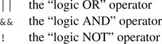
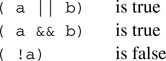
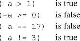
These operators consider their operands as logical (Boolean) values using the rule mentioned previously, and they return a logical value. Here are some trivial examples (assume that a = 17 and b = 1, or in other words they are both true):
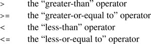
There are, then, a number of operators that compare numbers (integers of any kind, and floating-point values too) and return logic values. They are:
== the “equal-to” operator, notice it is composed of two equal signs to distinguish it from the “assignment” operator we used before.
!= the “NOT-equal to” operator
Here are some examples (assuming a = 10):
Back to the while loop: We said that as long as the expression in parentheses produces a true logic value (that is, any integer value but 0 ), the program execution will continue around the loop. When the expression produces a false logic value, the loop will terminate and the execution will continue from the first instruction after the closing curly bracket.
Notice that the evaluation of the expression is done first, before the curly bracket content is executed (if it ever is), and is then reevaluated each time.
Here are a few curious loop examples to consider:
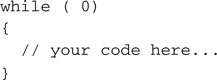
A constant false condition means that the loop will never be executed. This is not very useful. In fact I believe we have a good candidate for the “world’s most useless code” contest!
Here is another example:
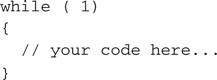
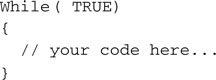
A constant true condition means that the loop will execute forever. This is useful and is in fact what we will use for our main program loops from now on. For the sake of readability, a few purists among you will consider using a more elegant approach, defining a couple of constants:
![]()
And using them consistently in their code, as in:
It is time to add a few new lines of code to the loops.c source file and put the while loop to good use:
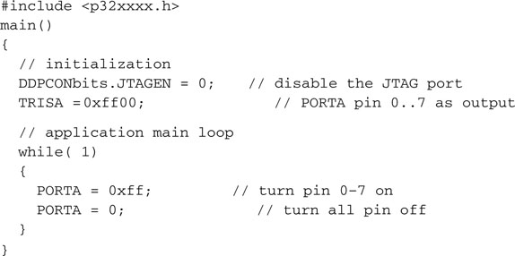
The structure of this example program is essentially the structure of every embedded control program written in C. There will always be two main parts:
An Animated Simulation
Use the Project Build checklist to compile and link the loops.c program. Also use the MPLAB SIM Simulator Setup checklist to prepare the software simulator.
To test the code in this example with the simulator, I recommend you use the Animate mode (Debugger | Animate). In this mode, the simulator executes one C program line at a time, pausing shortly after each one to give us time to observe the immediate results. If you add the PORTA special-function register to the Watch window, you should be able to see its value alternating rhythmically between 0xff and 0x00.
The speed of execution in Animate mode can be controlled with the Debug | Settings dialog box, selecting the Animation/Real Time Updates tab, and modifying the Animation Step Time parameter, which by default is set to 500 ms. As you can imagine, the Animate mode can be a valuable and entertaining debugging tool, but it gives you quite a distorted idea of what the actual program execution timing will be. In practice, if our example code was to be executed on a real hardware target, say an Explorer16 demonstration board (where the PIC32 is running at, say, 72 MHz), the LEDs, connected to the PortA output pins, would blink too fast for our eyes to notice. In fact, each LED would be turned on and off several million times each second.
To slow things down to a point where the LEDs would blink nicely just a couple of times per second, I propose we use a timer so that in the process we learn to use one of the key peripherals integrated in all PIC® microcontrollers. For this example we will choose Timer1, the first of five modules available inside the PIC32MX360FJ512L models (see Figure 2.1). This is one of the most flexible and simple peripheral modules. All we need is to take a quick look at the PIC32 datasheet, check the block diagram and the details of the Timer1 control registers, and find the ideal initialization values.
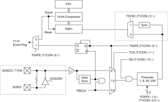
We quickly learn that there are three SFRs that control most Timer1 functions. They are:
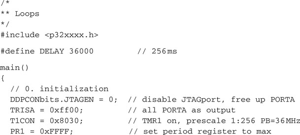
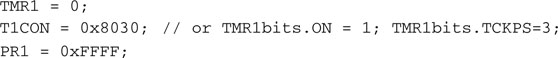
We can clear the TMR1 register to start counting from zero:
![]()
Then we can initialize T1CON so that the timer will operate in a simple configuration, where:

Once we assemble all the bits in a single 32-bit value, to assign to T1CON, we get:
![]()
or, in a more compact hexadecimal notation:
![]()
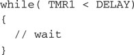
Once we are done initializing the timer, we enter a loop where we just wait for TMR1 to reach the desired value set by the constant DELAY.
Assuming a 36 MHz peripheral bus clock frequency will be used, we need to assign quite a large value to DELAY to obtain a delay of about a quarter of a second. In fact, the following formula dictates the total delay time produced by the loop:
Tdelay = (Fpb) * 256 * DELAY
With Tdelay = 256 ms and resolving for DELAY, we obtain the value 36000:
![]()
By putting two such delay loops in front of each PORTA assignment inside the main loop, we get our latest and best code example:
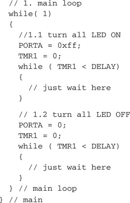
Note
Programming in C, the number of opening and closing curly brackets tends to increase rapidly as your code grows. After a very short while, even if you stick religiously to the best indentation rules, it can become difficult to remember which closing curly brackets belong to which opening curly brackets. By putting little reminders (comments) on the closing brackets, I try to make the code easier to follow and more readable. Also, by using the Ctrl + M shortcut in the editor window, you can quickly jump and alternate between matching brackets in your code.
It is time now to build the project and verify that it is working. If you have an Explorer 16 demonstration board available, you could try to run the code right away. The LEDs should flash at a comfortably slow pace, with a frequency of about two flashes per second.
Trying to run the same code with the MPLAB SIM simulator, though, you will discover that things are now way too slow. I don’t know how fast your PC is, but on mine, MPLAB SIM cannot get anywhere close to the execution speed of a true PIC32 microcontroller.
If you use the Animate mode, things get even worse. As we saw before, the animation adds a further delay of about half a second between the execution of each individual line of code. So, for pure debugging purposes, on the simulator feel free to change the DELAY constant to a much smaller value—36, for example!
Using the Logic Analyzer
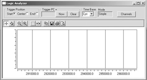
To complete this lesson and make things more entertaining, after building the project I suggest we play with a new simulation tool: the MPLAB SIM Logic Analyzer.
The Logic Analyzer gives you a graphical and extremely effective view of the recorded values for any number of the device output pins, but it requires a little care in the initial setup.
Before anything else, you should make sure that the Tracing function of the simulator is turned on:
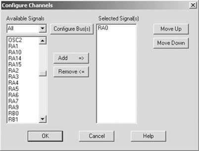
4. Now click the Channels button, to bring up the channel selection dialog box.
For future reference, all the preceding steps are listed in the Logic Analyzer Setup checklist.
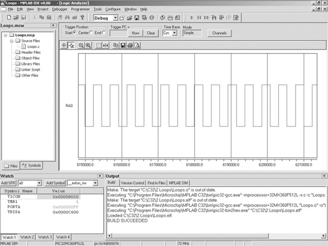
The Logic Analyzer window should display a neat square wave plot, as shown in Figure 2.5.
Debriefing
In this brief excursion, we learned about the way the MPLAB C32 compiler deals with program termination. For the first time, we gave our little project a bit of structure— separating the main() function in an initialization section and an infinite main loop. To do so, we learned about the while loop statements, and we took the opportunity to touch briefly on the subject of logical expressions evaluation. We closed the day with a final example, where we used a timer module for the first time and we played with the Logic Analyzer window to plot the RA0 pin output.
We will return to all these elements, so don’t worry if you have more doubts now than when we started; this is all part of the learning experience.
Notes for the Assembly Experts
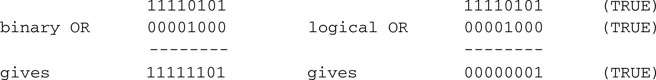
Logic expressions in C can be tricky for the assembly programmer who is used to dealing with binary operators of identical names (AND, OR, NOT …). In C there is a set of binary operators, too, but I purposely avoided showing them in this lesson to avoid mixing things up. Binary logic operators take pairs of bits from each operand and compute the result according to the defined table of truth. Logic operators, on the other hand, look at each operand (independently of the number of bits used) as a single Boolean value.
See the following examples on byte sized operands:
Notes for the 8-Bit PIC Microcontroller Experts
I am sure you noticed: Timer0 has disappeared! The good news is, you are not going to miss it. In fact, the remaining five timers of a PIC32 are so loaded with features that there is no functionality in Timer0 that you are going to feel nostalgic about. All the SFRs that control the timers have similar names to the ones used on PIC16 and PIC18 microcontrollers and are pretty much identical in structure. Still, keep an eye on the datasheet; the designers managed to cram in several new features, including:
Notes for the 16-Bit PIC Microcontroller Experts
For the PIC24 and dsPIC experts among you there will be no surprises with the PIC32. The timer modules are designed to be highly compatible with the previous 16-bit generation architecture. In fact, the same is true for all the peripheral modules of the PIC32MX family, with the PIC24 H series being the closest. Still, occasionally here and there the step up to a 32-bit bus has offered opportunities for improvements that the designers of the PIC32 could not resist.
The most dramatic difference, though, is represented by the decoupling between the core bus clock and the peripherals bus clock. This is a radical departure, for the first time in the PIC architectures history, from all previous generations’ bus designs. It was a necessary step that allows the MIPS core of the PIC32 to be free from the speed limitations of the Flash memory array and of the peripheral modules, to achieve much higher performance levels without sacrificing compatibility while operating within a very low power budget. In the next chapters we will learn more about the two internal buses, the oscillator module, and their proper configuration.
Notes for the C Experts
If you are used to programming in C on a personal computer or workstation, you expect that, upon termination of the main() function, control will be returned to the operating system. Though several real-time operating systems (RTOSs) are available for the PIC32, a large number of applications won’t need and won’t use one. This is certainly true for all the simple examples in this book. By default, the MPLAB C32 compiler assumes that there is no operating system to return control to.
Notes for the MIPS Experts
The MIPS experts among you might have been looking for a mention of the core 32-bit timer (yes, there are truly six timers inside the PIC32) and the hardware control registers typically offered for access through the coprocessor 0 (CP0) instructions. It was tempting to mention them, but I intentionally avoided it and decided not to use any of them for as long as possible. My purpose is to force you, the reader, to familiarize yourself with the PIC environment in which the MIPS core has been implanted. My intention is to demonstrate the use of the PIC32 and its peripherals as a true PIC microcontroller, the fastest ever designed so far, but still a true PIC machine.
Tips & Tricks
Some embedded applications are designed to run their main loops for months or years in a row without ever being turned off or receiving a reset command. But the control registers of a microcontroller are simple RAM memory cells. The probability that a power supply fluctuation (un-detected by the brown-out reset circuit), an electromagnetic pulse emitted by some noisy equipment in the proximity, or even a cosmic ray could alter their contents is a small but finite number. Given enough time (years) and depending on the application, you might see it happen. When you design applications that have to operate reliably on huge time scales, you should start seriously considering the need to provide a periodic “refresh” of the most important control registers of the essential peripherals used by the application.
Group the sequence of initialization instructions in one or more functions. Call the functions once at power-up, before entering the main loop, but also make sure that inside the main loop the initialization functions are called when idling and no other critical task is pending, so that every control register is reinitialized periodically.
Notes on Using the Peripheral Libraries
The MPLAB C32 tool suite comes with a complete set of standard C libraries and an additional set of peripherals libraries designed to simplify and standardize the use of all the internal resources of the PIC32. The peripheral libraries are specifically designed to provide an even higher level of compatibility with previous Microchip 16-bit architectures and in particular with the PIC24 series of microcontrollers. The following example uses the timers’ library timer.h to exemplify the advantages and disadvantages of relying on libraries.
Should we need to initialize the Timer1 module using the peripheral libraries, as in the “loops” projects we developed today, in place of the direct access to the Timer1 module registers:
we could use the following code:
![]()
The clear advantage is that you don’t need to add many comments to the two lines of code; they read pretty well already. This code is self-documenting. Additionally, if you misspell one of the parameter names, the compiler will promptly complain and point it out.
But it is not all roses, either. Although the function parameters are checked for spelling errors, in most cases there is no way for the compiler to tell whether you used the right parameter for the right function. For example, when configuring Timer2, the following error would go undetected:
![]()
It seems a pretty innocent mistake, but it would probably cause you to spend a few hours scratching your head to understand why the Timer2 prescaler is configured wrong, whereas it is all fine by the compiler.
The best advantage of using the libraries, the abstraction they offer, is also another source of potential frustration. Since they hide the implementation details from us, we are not given to know if, for example, the TMR1 register is already being cleared by the OpenTimer1() function or if we need to do it ourselves before invoking it. It turns out it is not, but you can verify that only if you visually get access to the library source files or you inspect them in the disassembly listing.
Further, although the PIC32MX device datasheet defines the official names for all the control registers (T1CON) and for each bit inside them (TCKPS), the parameters defined in the peripheral libraries have different names and spelling (T1_PS_1_256), although they try to mimic them closely. The new names can be found only in a separate set of documentation. You need to either study the Peripheral Library User Guide or inspect the timer.h include file and verify where each parameter is defined.
So, my personal recommendation regarding the use of the peripheral libraries is one of cautious and deliberate choice on a case-by-case basis. For some simple peripherals such as the I/O ports and the timers, I cannot see much of an advantage in using the library. After all, to select the correct parameters, you will still need to learn about each and every bit in each control register and be familiar with their meaning and correlation. Besides, is WriteTimer1( 0); really that much more readable than TMR1 = 0;?
When the complexity of the peripheral module is greater and the work the library functions are performing for us bring more value, such as is the case, for example, of the DMA library we will use later in the book, I recommend we take advantage of it.
In any case, throughout the rest of the book you will have several examples of both types of approaches and, as is often the case, it will be your personal programming style that will dictate when and where you will feel comfortable using the peripheral libraries, direct register access, or a mix of the two.
Exercises
Books
Ullman, L., and Liyanage, M., C Programming (Peachpit Press, Berkeley, CA, 2005). This is a fast-reading and modern book, with a simple step-by-step introduction to the C programming language.
Links
http://en.wikipedia.org/wiki/Control_flow#Loops. A wide perspective on programming languages and the problems related to coding and taming loops.
http://en.wikipedia.org/wiki/Spaghetti_code. Your code gets out of control when your loops start knotting …