
Day 1 The Adventure Begins
The Plan
This will be our first experience with the PIC32 32-bit microcontroller and, for some of you, the first project with the MPLAB® IDE Integrated Development Environment and the MPLAB C32 language suite. Even if you have never heard of the C language, you might have heard of the famous “Hello World!” programming example. If not, let me tell you about it.
Since the very first book on the C language, written by Kernighan and Ritchie several decades ago, every decent C language book has featured an example program containing a single statement to display the words “Hello World” on the computer screen. Hundreds, if not thousands, of books have respected this tradition, and I don’t want my books to be the exception. However, our example will be just a little different. Let’s be realistic—we are talking about programming microcontrollers because we want to design embedded-control applications. Though the availability of a monitor screen is a perfectly safe assumption for any personal computer or workstation, this is definitely not the case in the embedded-control world. For our first embedded application we’d better stick to a more basic type of output: a digital I/O pin. In a later and more advanced chapter, we will be able to interface to an LCD display and/or a terminal connected to a serial port. But by then we will have better things to do than writing “Hello World!”
Preparation
Whether you are planning a small outdoor trip or a major expedition to the Arctic, you’d better make sure you have the right equipment with you. Our exploration of the PIC32 architecture is definitely not going to be a matter of life or death, but you will appreciate the convenience of following the few simple steps outlined here before getting your foot out the door … ahem, I mean before starting to type the first few lines of code.
So, let’s start by verifying that we have all the necessary pieces of equipment ready and installed (from the attached CD-ROM and/or the latest version available for download from Microchip’s PIC32 Web site at www.microchip.com/PIC32). You will need the following:
Now let’s use the New Project Setup checklist to create a new project with the MPLAB IDE. From the Project menu, select the Project Wizard. This will bring up a short but useful sequence of little dialog boxes that will guide us through the few steps required to create a new project in an orderly and clean way:
Since this is our first time, let’s continue with the following additional steps:
shortcut or by clicking the corresponding

Note
You will notice that, after saving the file, the color of the three lines of text in the editor window changes to green. This is because the MPLAB Editor has been able to recognize your file as a C language source file (the .c extension tipped it off) and is now applying the default context-sensitive color rules. According to theses rules, green is the color assigned to comments, blue is the color assigned to language keywords, and black is used for all the remaining code.
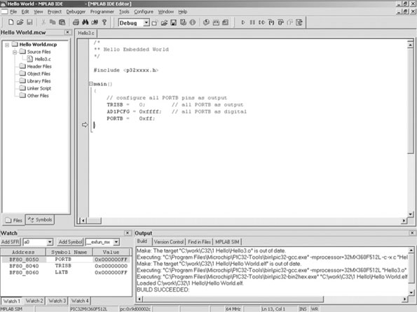
Once you are finished, your project window should look like the one in Figure 1.1. If you cannot see the project window, select View | Project. A small check mark should appear next to the item in the View menu. Also make sure that the Files tab is selected. We will review the use of the other tab (Symbols) in a later chapter.
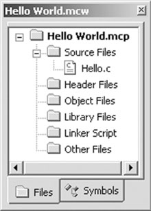
Depending on your personal preferences, you might now want to “dock” this window to assign it a specific place on your workspace rather than keeping it floating. You can do so by right-clicking with your mouse on the title bar of the small window to access the context menu and selecting the Dockable option. You can then drag it to the desired edge of the screen, where it will stick and split the available space with the editor.
The Adventure Begins
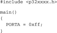
It is time to start writing some code. I can sense your trepidation, especially if you have never written any C code for an embedded-control application before. Our first line of code is:
![]()
This is not yet a proper C statement but an instruction for the preprocessor (which feeds the compiler) with the request to include the content of a device-specific file before proceeding any further. The pic32xxxx.h file, in its turn, contains more #include instructions designed so that the file relative to the device currently selected in the project is included. That file in our case is p32mx360f5121.h. We could have used its name directly, but we chose not to in order to make the code more independent and hopefully easier to port, in the future, to new projects using different models.
If you decide to further inspect the contents of the p32mx360f5121.h file (it is a simple text file that you can open with the MPLAB editor), you will see that it contains an incredibly long list of definitions for all the names of the internal special-function registers (often referred to in the documentation as the SFRs) of the chosen PIC32 model. If the include file is accurate, those names reflect exactly those being used in the device datasheet and the PIC32 reference manual.
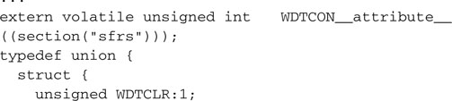
Here is a segment of the p32mx360f5121.h file in which the special-function register that controls the watchdog module (WDTCON) and each of its individual bits are assigned their conventional names:
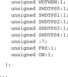
Back to our Hello.c source file; let’s add a couple more lines that will introduce you to the main() function:

What we have now is already a complete, although still empty and pretty useless, C language program. In between those two curly brackets is where we will soon put the first few instructions of our embedded-control application.
Independently of this function position in the file, whether in the first lines on top or the last few lines in a million-lines file, the main() function is the place where the microcontroller will go first at power-up or after each subsequent reset. This is actually an oversimplification. After a reset or at power-up, but before entering the main() function, the microcontroller will execute a short initialization code segment automatically inserted by the MPLAB C32 linker. This is known as the Startup code or crt0 code (or simply c0 in the traditional C language literature). The Startup code will perform basic housekeeping chores, including the all important initialization of the stack, among many other things.
Our mission is to activate for the first time one or more of the output pins of the PIC32. For historical reasons, and to maintain the greatest compatibility possible with the many previous generations of PIC microcontrollers, the input/output (I/O) pins of the PIC32 are grouped in modules or ports, each comprising up to 16 pins, named in alphabetical order from A to H. We will start logically from the first group known as PortA. Each port has several special-function registers assigned to control its operations; the main one, and the easiest to use, carries traditionally the same name as the module (PORTA).
Notice how, to distinguish the control register name from the module name in the following, we will use a different notation for the two: PORTA (all uppercase) will be used to indicate one of the control registers; PortA will refer to the entire peripheral module.
According to the PIC32 datasheet, assigning a value of 1 to a bit in the PORTA register turns the corresponding output pin to a logic high level (3.3 V). Vice versa, assigning a value of 0 to the same bit will produce a logic level low on the output pin (0 V).
Assignments are easy in C language—we can insert a first assignment statement in our project as in the following example:
First, notice how statements in C must be terminated with a semicolon. Then notice how they resemble mathematical equations—they are not!
An assignment statement has a right side, which is computed first. A resulting value is obtained (in this case it was simply a constant expressed in hexadecimal notation) and it is then transferred to the left side, which acts as a receiving container. In this case it was the special-function PORTA register of the microcontroller.
Note
In C language, by prefixing the literal value with 0x (zero x), we indicate the use of the hexadecimal radix. For historical reasons a single 0 (zero) prefix is used for the octal notation (does anybody use octal anymore?). Otherwise the compiler assumes the default decimal radix.
Compiling and Linking
Now that we have completed the main() and only function of our first C program, how do we transform the source into a binary executable?
Using the MPLAB Integrated Development Environment (IDE), it’s very easy! It’s a matter of a single click of your mouse in an operation called a Project Build. The sequence of events is actually pretty long and complex, but it is mainly composed of two steps:
All this is performed in a very rapid sequence as soon as you ask MPLAB to build your project. Each group of files, as presented in the project window (refer back to Figure 1.1), will be used during the project build to assist in the compiling or linking phase:
The last two sections of the project window are treated differently:
The Linker Script
Just like the p32xxxx.h include file tells the compiler about the names (and sizes) of device-specific SFRs, the (default) linker script informs the linker about the SFRs’ predefined position in memory (according to the selected device datasheet). It also provides other essential services such as:
Now, if you are curious like me, you might want to take a look inside. The linker script file, it turns out, is a simple text file, although with the .ld extension. It can be opened and inspected using the MPLAB editor. Assuming you accepted the default values when you installed MPLAB on your hard drive, you will find the default linker script for the PIC32MX360F512L microcontroller by opening the procdefs.ld file found in the following directory:
![]()
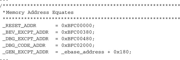
Wow, I know, my head is spinning, too! It took me half an hour to find my way through the labyrinth of subdirectories created during the MPLAB installation. But the reality is that the linker will find it and use it automatically, and you will hardly ever have to see or worry about it again. Here is a segment of the script where the address of the reset vector, the general exception vector, and a few other critical entry points are defined:
Note
Don’t try to open the procdefs.ld from Windows Explorer or using the default Windows Notepad application; it won’t look pretty. This file was generated in a Unix environment and does not contain the standard end-of-line sequence used by Windows programs. Instead use the MPLAB Editor as I suggested.
Building the First Project
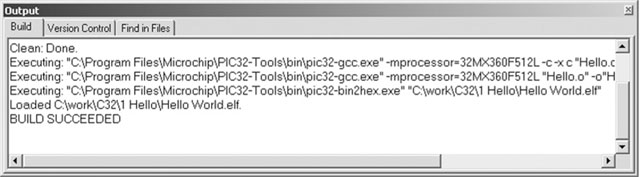
Select the option Build All from the Project menu or click the corresponding ![]() (Build All) button in the project toolbar. MPLAB will open a new window; the content of yours should be very similar to what I obtained, shown in Figure 1.2.
(Build All) button in the project toolbar. MPLAB will open a new window; the content of yours should be very similar to what I obtained, shown in Figure 1.2.
Should you prefer a command-line interface, you will be pleased to learn that there are alternative methods to invoke the compiler and the linker and achieve the same results without using the MPAB IDE, although you will have to refer to the MPLAB C32 compiler user guide for instructions. In this book, we will stick with the MPLAB IDE interface and will use the appropriate checklists to make it even easier.
Using the Simulator
Select Debugger | Select Tool | MPLAB SIM to choose and activate the software simulator as the main debugging tool for this project. I recommend that you get in the habit of using the MPLAB SIM debugger setup checklist to configure a number of parameters that will improve your simulation experiences, although we won’t need it during this first simulation. Let’s perform instead another and all-important general configuration step of MPLAB itself.
Select the Configure | Settings item from the MPLAB menu and, inside the large and complex dialog box that will pop up, select the Debugger tab.
As illustrated in Figure 1.3, I recommend that you check three of the options available to instruct MPLAB to automatically perform a few useful tasks:
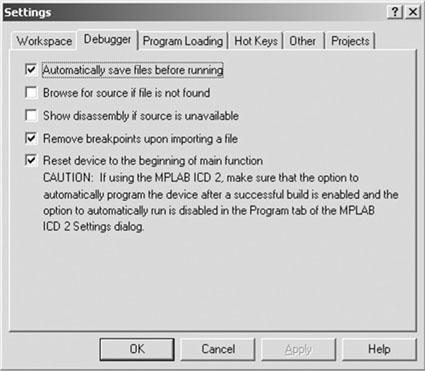
The last task, in particular, might seem redundant, but it is not. If you remember, as was briefly mentioned at the beginning of this chapter, there is a small segment of code (crt0 or Startup code) that the linker places automatically for us between the actual reset vector and our code. If we do not instruct MPLAB otherwise, the simulator will attempt to step through it, and since there is no C source code to show for it, it would have to happen in the disassembly window. Not that there would be anything wrong with that; actually, I invite you to try that sometime to inspect this mysterious (but so useful) segment of code. The fact is that we are just not ready for it yet and, after all, our focus in this exploration is 100 percent on the C language programming of the PIC32 rather than the underlying MIPS assembly.
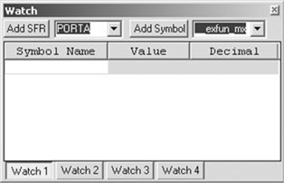
If all is well, before trying to execute the code let’s also open a Watch window and add the PORTA special-function register to it:
Finding a Direction
It is time to hit the books, specifically the PIC32MX datasheet (Chapter 13 focuses on the I/O ports detail). PortA is a pretty complex, 12-pin-wide port. Each one of the pins is controlled by a small block of logic, represented in Figure 1.5.
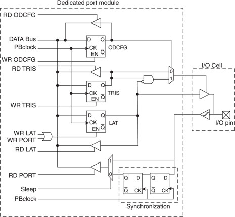
Although completely understanding the diagram in Figure 1.5 is beyond the scope of our explorations today, we can start by making a few simple observations. There are only three signals that eventually reach the I/O cell. They are the data output, the data input, and the tristate control signals. The latter is essential to decide whether the pin is to be used as an input or an output, which is often referred to as the direction of the pin.
From the datasheet, again, we can determine the default direction for each pin—that is, in fact, configured as an input after each reset or power up event. This is a safety feature and a standard for all PIC microcontrollers. The PIC32 makes no exception.
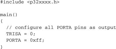
The TRISA special-function register allows us to change the direction of each individual pin on PortA. The rule is simple to remember:
So, we need to add at least one more assignment to our program if we want to change the direction of all the pins of PortA to output and see their status change. Here is how our simple project looks after the addition:
We can now retest the code by repeating the following few steps:
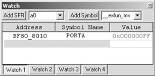
If all went well, you should see the content of PORTA change to 0xFF, highlighted in the Watch window in red. Hello Embedded World!
The JTAG Port
Our first choice of PortA was dictated partially by the alphabetical order and partially by the fact that on the Explorer16 demonstration boards, PortA pins, RA0 through RA7, are conveniently connected to 8 LEDs. So, if you try and execute this example code on the actual demo board using an in-circuit debugger, you will have the satisfaction of seeing all the LEDs turn on, nice and bright … or perhaps not?
There is one more important detail affecting the operation of a few PortA pins that you need to be aware of. Where previous generations of PIC microcontrollers used a two-wire protocol to connect to an in-circuit programmer and/or debugger, known as the ICSP/ICD interface, the PIC32 offers an additional interface, widely adopted among 32-bit architectures, known as the JTAG interface.
Note
The PIC24 experts will not fail to point out that several 16-bit large pin-count devices were already offering JTAG to support boundary scan features. With the PIC32 architecture, the JTAG functionality is extended to include all programming and debugging features.
In fact, for all debugging and programming purposes, the JTAG and the ICSP/ICD interface are now equivalent and the choice between the two will be dictated more by personal preference, the availability and cost of (Microchip own and third-party) tools, and/or the number of pins required. In this last respect, the ICSP/ICD interface has a small advantage over the JTAG interface since it requires only half the microcontroller I/Os. On the other side, if the boundary scan functionality is required, the JTAG interface is the one and only option.
As a consequence of the decision to offer both interfaces, the designers of the PIC32 had to make sure that both debugging options were available by default upon reset or power-up of the device. The JTAG port pins are multiplexed with PortA pins RA0, RA1, RA4, and RA5, over which they take priority.
The PIC32 Starter Kit is an example of a programming and debugging tool that uses the JTAG port. The MPLAB REAL ICE and the MPLAB ICD2 instead use the traditional ICSP/ICD port.
If you intend to test the code developed so far on the Explorer 16 board using the MPLAB REAL ICE or the MPLAB ICD2 in circuit debuggers, you will have to remember to disable the JTAG port to gain access to all the pins of PortA and therefore all the LEDs. Here is all it takes:
![]()
After all, only one more assignment statement needs to be added at the top of the main function. Instead of assigning a new value to the entire DDPCON register (in charge of the configuration of the Debug Data Ports), we used the special C language notation to access individual bits (or groups of bits) within a word. We will expand on these subjects in the next few chapters.
If you intend to test the code on the Explorer 16 board using the PIC32 Starter Kit and a 100-pin PIM adapter, you must not disable the JTAG port. You will still have control on the remaining pins of PortA: RA2, RA3, RA6, and RA7. Don’t be envious; you have three more LEDs that you can control on the Starter Kit board itself, connected to PortD instead: RD0, RD1, and RD2. In fact, even if you don’t have an Explorer 16 board but just a PIC32 Starter Kit, you could change the code in the previous examples, replacing all references to PortA registers with the PortD equivalents: TRISD and PORTD. Perhaps it will be less spectacular but equally instructive!
Testing PORTB
To complete our day of exploration, we will now investigate the use of one more I/O port, PortB. It is simple to edit the program and replace the two PortA control registers assignments with TRISB and PORTB.
Rebuild the project and follow the same steps we did in the previous exercise and you’ll get a new surprise: The same code that worked for PortA does not work for PortB!
Don’t panic—I did it on purpose. I wanted you to experience a little PIC32 migration pain. It will help you learn and grow stronger.
It is time to go back to the datasheet and study in more detail the PIC32 pin-out diagrams. There are two fundamental differences between the 8-bit PIC microcontroller architectures and the new 16- and 32-bit architectures:
By default, pins multiplexed with “analog” inputs are disconnected from their “digital” input ports. This explains what was happening during our last attempt. All PortB pins of the PIC32 are, by default at power-up, assigned an analog input function; therefore, reading the PORTB register returns all 0s. Notice, though, that the output latch of PortB has been correctly set, although we cannot see it through the PORTB register. To verify it, check the contents of the LATB register instead.
To reconnect the PortB input pins to the digital inputs, we have to act on the ADC module configuration. From the datasheet, we learn that the SFR AD1PCFG controls the analog/digital assignment of each pin (see Figure 1.7).
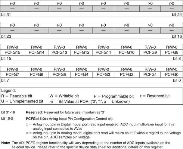
Assigning a 1 to each bit in the AD1PCGF SFR will accomplish the task and convert the pin into a digital input. Our new and complete program example is now:
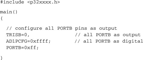
This time, compiling and single-stepping through it will give us the desired results (see Figure 1.8 ).
Mission Debriefing
After each expedition, there should be a brief review. Sitting on a comfortable chair in front of a cool glass of … water, it’s time to reflect on what we have learned from this first experience.
Writing a C program for a PIC32 microcontroller can be very simple, or at least no more complicated than an assembly or 8-bit equivalent project. Two or three instructions, depending on which port we plan to use, can give us direct control over the most basic tool available to the microcontroller for communication with the rest of the world: the I/O pins.
Also, there is nothing the MPLAB C32 compiler can do to read our minds. Just as in assembly, we are responsible for setting the correct direction of the I/O pins. We are still required to study the datasheet and learn about the small differences between the 8-bit and 16-bit PIC microcontrollers we might be familiar with and the new 32-bit breed.
As high level as the C programming language is thought to be, writing code for embedded-control devices still requires us to be intimately familiar with the finest details of the hardware we use.
Notes for the Assembly Experts
If you have difficulties blindly accepting the validity of the code generated by the MPLAB C32 compiler, you might find comfort in knowing that, at any given point in time, you can decide to switch to the Disassembly Listing view (see Figure 1.9). You can quickly inspect the code generated by the compiler, since each C source line is shown in a comment that precedes the segment of code it generated.
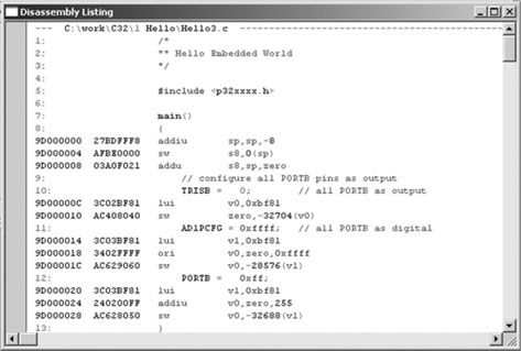
You can even single-step through the code and do all the debugging from this view, although I strongly encourage you not to do so or limit the exercise to a few exploratory sessions as we progress through the first chapters of this book. Satisfy your curiosity, but gradually learn to trust the compiler. Eventually, use of the C language will give a boost to your productivity and increase the readability and maintainability of your code.
As a final exercise, I would encourage you to open the Memory Usage Gauge window by selecting View | Memory Usage Gauge (see Figure 1.10).
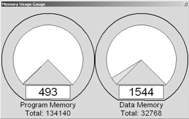
Don’t be alarmed, even though we wrote only three lines of code in our first example and the amount of program memory used appears to be already up to 490 or more words. This is not an indication of any inherent inefficiency of the C language. There is a minimum block of code that is always generated (for our convenience) by the MPLAB C32 compiler. This is the Startup code (crt0) that we mentioned briefly before. We will return to it, in more detail, in the following chapters as we will discuss variable initialization, memory allocation, and interrupts.
Notes for the PIC MCU Experts
Those of you who are familiar with the PIC16, PIC18, and even the PIC24 architecture will find it interesting that all PIC32 SFRs are now 32-bit wide. But in particular, if you are familiar with the PIC24 and dsPIC architecture, it might come to you as a surprise that the ports did not scale up! Even if PORTA and TRISA are now 32-bit wide registers, the PortA module still groups fewer than 16 pins, just like in the PIC24. You will realize in the following chapters how this has several positive implications for easy code migration up from the 16-bit architectures while granting optimal performance to the 32-bit core.
Whether you are coming from the 8-bit or the 16-bit PIC/dsPIC world, with the PIC32 peripheral set you will feel at home in no time!
Notes for the C Experts
Certainly we could have used the printf() function from the standard C libraries. In fact they are readily available with the MPLAB C32 compiler. But we are targeting embedded-control applications and we are not writing code for multigigabyte workstations. Get used to manipulating low-level hardware peripherals inside the PIC32 microcontrollers. A single call to a library function, like printf(), could have added several kilobytes of code to your executable. Don’t assume a serial port and a terminal or a text display will always be available to you. Instead develop a sensibility for the “weight” of each function and library you use in light of the limited resources available in the embedded design world.
Tips & Tricks
The PIC32MX family of microcontrollers is based on a 3 V CMOS process with a 2.0 V to 3.6 V operating range. As a consequence, a 3.3 V power supply (Vdd) is used on most applications and demonstration boards; this limits the output voltage of each I/O pin when producing a logic high output. Interfacing to 5 V legacy devices and applications, though, is really simple:
Watch out
Be careful with I/O pins that are multiplexed with analog inputs (most PortB pins, for example); they cannot tolerate voltages above 3.6 V!
Exercises
If you have the Explorer 16 board and an in-circuit debugger:
If you have the PIC32 Starter Kit:
In both cases you can:
Books
Kernighan, B., and Ritchie, D., The C Programming Language (Prentice-Hall, Englewood Cliffs, NJ). When you read or hear programmers talk about the “K&R,” also known as “the white book,” they mean this book. The C language has evolved quite a bit since the first edition was published in 1978. The second edition (1988) includes the more recent ANSI C standard definitions of the language, which are closer to the standard the MPLAB C32 compiler adheres to (ISO/IEC 9899:1990 also known as C90).
Links
http://en.wikibooks.org/wiki/C_Programming. This is a Wiki-book on C programming and as such it is a bit of a work in progress. It’s convenient if you don’t mind doing all your reading online. Hint: Look for the chapter called “A Taste of C” to find the omnipresent “Hello World!” example.