
Day 6 Memory
The Plan
The beauty of using a completely integrated, single-chip microcontroller device lies in its reduced size, its increased robustness, and the convenience of having a complete set of peripherals harmoniously preassembled for us, ready for use. Unfortunately, as most embedded-control designers quickly realize, it is the amount of available memory (Flash and RAM) that most often seems to dictate the cost and availability of a product. Learning how to make the most use of both is imperative.
Today we will review the basics of string declaration and manipulation in C language as an excuse to investigate the memory allocation techniques used by the MPLAB® C32 compiler. The PIC32 core offers some pretty advanced features never before seen on 8- or 16-bit PIC® architectures. These include the ability to remap memory spaces, to cache memory contents, and to share the memory bus with a direct memory access (DMA) mechanism. We will use several tools, including the Disassembly Listing window, the Memory window, and the Map file, to investigate how the MPLAB C32 compiler and linker operate in combination to generate the most compact and efficient code.
Preparation
This lesson will be performed exclusively with software tools, including the MPLAB IDE, the MPLAB C32 compiler, and the MPLAB SIM simulator.
Use the New Project Setup checklist to create a new project called Strings and a new source file, similarly called strings.c.
The Exploration
Strings are treated in C language as simple ASCII character arrays. Every character composing a string is assumed to be stored sequentially in memory in consecutive 8-bit integer elements of the array. After the last character of the string, an additional byte containing a value of 0 (represented in a character notation with ’�’ ) is added as a termination flag.
Note
This is just a convention that applies to the standard C string manipulation library string.h. It would be entirely possible, for example, to define a different library that, for example, stores strings in arrays where the first element is used to record the length of the string. In fact, Pascal programmers will be very familiar with this method.
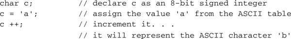
Let’s get started by reviewing the declaration of a variable containing a single character:
![]()
As we have seen from the previous lessons, this is how we declare an 8-bit integer (character) that is treated as a signed value ( — 128 … +127) by default.
We can declare and initialize it with a numerical value:
![]()
Or we can declare and initialize it with an ASCII value:
![]()
Note the use of the single quotes for ASCII character constants. The result is the same, and to the C compiler there is absolutely no distinction between the two declarations; characters are numbers.
We can now declare and initialize a string as an array of 8-bit integers (characters):
![]()
In this example, we initialized the array using the standard notation for numerical arrays. But we could have also used a far more convenient notation (a shortcut) specifically created for string initializations:
![]()
To further simplify things and save you from having to count the number of characters composing the string (thus preventing human errors), you can use the following notation:
![]()
The MPLAB C32 compiler will automatically determine the number of characters required to store the string while automatically adding a termination character (zero) that will be useful to the string manipulation routines later to correctly identify the string length. So, the preceding example is, in truth, equivalent to the following declaration:
![]()
Assigning a value to a char (8-bit integer) variable and performing arithmetic on it is no different than performing the same operation on any integer type:
The same operations can be performed on any element of an array of characters (string), but there is no simple shortcut, similar to the one used above, for the initialization that can assign a new value to an entire string:
![]()
Including the string.h file at the top of your source file, you’ll gain access to numerous useful functions that will allow you to:
![]()
![]()
![]()
and many more.
Memory Space Allocation
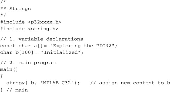
Though a compiler’s job is that of generating the code that manipulates variables, it is the linker that is responsible for deciding where variables are to be placed in memory, finding a physical address for every object in the memory space(s) available. Just as with numerical initializations, every time a string variable is declared and initialized, as in:
![]()
three things happen:
In other words, the string “Exploring the PIC32” ends up using twice the space you would expect, because a copy of it is stored in Flash program memory and space is reserved for it in RAM memory, too. Additionally, you must consider the initialization code and the time spent in the actual copying process. If the string is not supposed to be manipulated during the program execution but is only used “as is,” transmitted to a serial port or sent to a display, there is no need to waste precious resources. Declaring the string as a constant will save RAM space and initialization code and time:
![]()
Now the MPLAB C32 linker will only allocate space in program memory, in the rodata code section, where the string will be directly accessible. The string will be treated by the compiler as a direct pointer into program memory and, as a consequence, there will be no need to waste RAM space.
In the previous examples of this lesson, we saw other strings implicitly defined as constants—for example, when we wrote:
![]()
The string “HELLO” was implicitly defined as of const char type and similarly assigned to the rodata section in program memory.
Note
If the same constant string is used multiple times throughout the program, the MPLAB C32 compiler will automatically store only one copy in the rodata section to optimize memory use, even if all optimization features of the compiler have been turned off.
We will start investigating these issues with the MPLAB SIM simulator and the following short snippet of code:
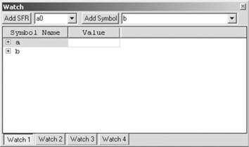
A little + symbol enclosed in a box will identify these variables as arrays and will allow you to expand the view to identify each individual element (see Figure 6.2).
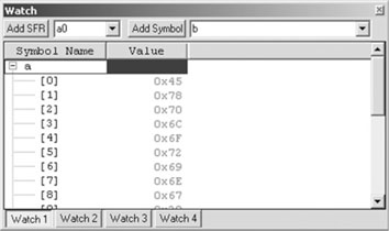
By default, MPLAB shows each element of the array as hex values, but you can change the display to ASCII characters or to reflect your personal preferences:
You will be presented with the Watch window Properties dialog box (see Figure 6.3).
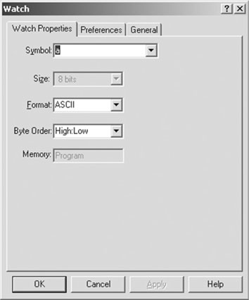
From this dialog box you can change the format used to display the content of the selected array element, but you can also observe the Memory field (grayed) that tells you where the selected variable is allocated: data or code space.
If you select the Properties dialog box for the constant string a, you will notice that the memory space is indicated as Program, confirming that the constant string is using only the minimum amount of space required in the Flash program memory of the PIC32 and no RAM needs to be assigned to it.
On the contrary, the Properties dialog box will reveal how the string b is allocated in a File Register, or in other words RAM memory.
Each variable value can be simultaneously presented in multiple formats by adding new columns to the table inside the Watch window:
Continuing our investigation, notice how the string a appears to be already initialized; the Watch window shows it’s ready to use, right after the project build.
The string b, on the other hand, appears to be still empty, uninitialized. Only when we enable the MPLAB SIM simulator and we click the reset button for the first time to reach the beginning of the main function is the string b initialized with the proper value (see Figure 6.4).
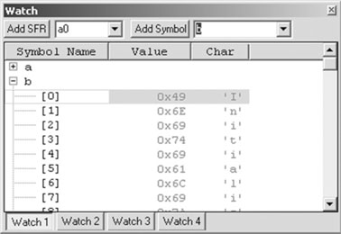
As we have seen, b is allocated in RAM space, and the Startup code must be executed first for the variable to be initialized and “ready for use.”
Once more we can use the Disassembly Listing window to observe the code produced by the compiler:
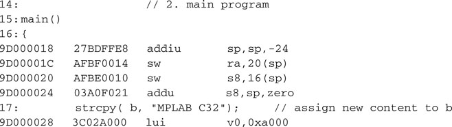
We can see that the main() function is short and followed by the strcpy() library function full disassembly appended at the bottom of the listing. Don’t let the length and apparent complexity of the function distract you; it is a pretty optimized piece of code that is designed to take maximum advantage of the 32-bit bus and cache system used by the PIC32. Its analysis is beyond the scope of our explorations today.
You should instead appreciate that this is the only routine attached. Although the string.h library contains dozens of functions, and the include file string.h contains the declarations for all of them, the linker is wisely appending only the functions that are actually being used.
Looking at the Map
Another tool we have at our disposal to help us understand how strings (and in general any array variable) are initialized and allocated in memory is the .map file. This text file, produced by the MPLAB C32 linker, can be easily inspected with the MPLAB editor and is designed specifically to help you understand and resolve memory allocation issues.
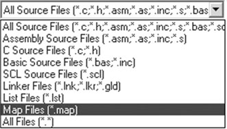
To find this file, look for it in the main project directory where all the project source files are. Select File | Open and then browse until you reach the project directory. By default the MPLAB editor will list all the .c files, but you can change the File Type field to .map (see Figure 6.5).
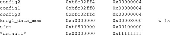
Map files tend to be pretty long and verbose, but by learning to inspect only a few critical sections, you will be able to find a lot of useful data. Essentially this file is composed of three parts:
![]()
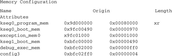
You will find some of the area names to be intuitively understandable, whereas others (that follow a long MIPS tradition) will look rather arcane.
![]()
![]()
![]()
![]()
Note
The name of this section (.text), although somewhat misleading, follows a long tradition among C compilers. It has been used since the original implementation of the very first C compiler.
![]()
![]()
![]()
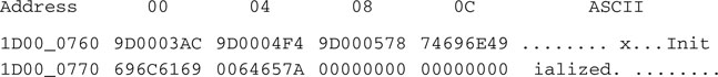
To verify what can be really found at such addresses, we will need to use the Memory window (select View | Memory). Here select the Data View tab to visualize the memory contents in classic hex dump format. Then right-click with the mouse pointer inside the Memory window and choose Go To from the context menu (or press Ctrl + G) to activate the Go To dialog box (Figure 6.6).
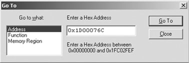
In the Hex Address field, type the address found above (0x9d0076c) and press the Go To button. The Memory window will center around the selected address where you will be able to recognize the initialization value we have been looking for.
Pointers
Pointers are variables used to refer indirectly (point to) other variables or part of their contents. Pointers and strings go hand in hand in C programming; in general they are a powerful mechanism to work on any array data type. They’re so powerful, in fact, that they are also one of the most dangerous tools in a programmer’s hands and a source of a disproportionately large share of programming bugs. Some programming languages, such as Java, have gone to the extreme of completely banning the use of pointers in an effort to make the language more robust and verifiable.
The MPLAB C32 compiler takes advantage of the PIC32 architecture to manage with ease large amounts of data memory and program memory (up to 4GB). The MPLAB C32 compiler makes no distinction between pointers to data memory objects and const objects allocated in program memory space. This allows a single set of standard functions to manipulate variables and/or generic memory blocks as needed from both spaces.
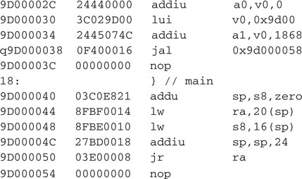
The following classic program example compares the use of pointers versus indexing to perform sequential access to an array of integers:
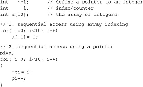
In 1. we performed a simple for loop, and at each round in the loop we used i as an index in the array. To perform the assignment, the compiler will have to multiply the value of i by the size of the array element in bytes (4) and add the resulting offset to the initial address of the array a.
In 2. we initialized a pointer to point to the initial address of the array a. At each round in the loop we simply used the pointer indirection operator (*) to perform the assignment; then we simply incremented the pointer.
Comparing the two cases, we see how, by using the pointer, we can save at least one multiplication step for each round in the loop. If inside the loop the array element is used more times, the performance improvement will be proportionally greater.
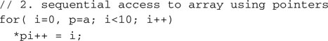
Pointer syntax can become very “concise” in C, allowing for some pretty effective code to be written but also opening the door to more bugs.
At a minimum, you should become familiar with the most common contractions. The previous snippet of code is more often reduced to the following:
Also note that an empty pointer—that is, a pointer without a target—is assigned a special value NULL, which is implementation specific and defined in stddef.h.
The Heap
One of the advantages offered by the use of pointers is the ability to manipulate objects that are defined dynamically (at run time) in memory. The heap is the area of data memory reserved for such use, and a set of functions, part of the standard C library stdlib.h, provides the tools to allocate and free the memory blocks. They include at a minimum the two fundamental functions: malloc( ) and free( ).
![]()
The first function takes a block of memory of requested size from the heap and returns a pointer to it.
![]()
The second function returns the block of memory pointed to by ptr to the heap.
The MPLAB C32 linker places the heap in the RAM memory space left unused above all project global variables and the reserved stack space. Although the amount of memory left unused is known to the linker, you will have to explicitly instruct the linker to reserve an exact amount for use by the heap, the default size being zero.
Use the Project | BuildOptions | Project menu command to open the Build Options dialog box, select the MPLAB PIC32 Linker tab, and define the heap size in bytes.
As a general rule, allocate the largest amount of memory possible. This will allow the malloc() function to make the most efficient use of available memory. After all, if it is not assigned to the heap, it will remain unused.
The PIC32MX Bus
If the previous section, exploring techniques employed by the MPLAB C32 compiler and linker for the allocation of variables, had your head spinning and you feel a little dizzy, you might want to take a break now!
If on the contrary it only served to increase your curiosity, follow me for a little longer as we continue the exploration to investigate the reasons for the architectural foundations of the PIC32 memory bus.
The PIC32 architecture is different from all previous PIC microcontroller architectures (both 8- and 16-bit) with which you might be familiar. The PIC32 follows the more traditional Von Neumann model instead of the classic (PIC) Harvard model. The big difference is that two completely separate and independent buses are no longer available. A single large (32-bit) bus gives access to both the Program Memory (Flash) and Data Memory (RAM) now.
The Von Neumann approach allows for a more economical implementation (two separate 32-bit buses would have been very expensive) and at the same time provides a simpler unified programming model, eliminating the need for the many “tricks” used by 8- and 16-bit Harvard architectures to allow access to data tables in program memory and finally removing important barriers, allowing for the first time a PIC processor to execute code from RAM memory!
It would seem that all these advantages would be immediately offset by a reduction in performance, but this is not the case. In fact a five-stage pipeline mechanism and a prefetch cache mechanism are used to allow efficient access to the bus while maintaining an unprecedented sustained execution rate of one instruction per clock cycle.
Note
Later, in the next chapter, we will have the opportunity to look in detail at the operation of the memory cache module and analyze its impact on device performance. Without anticipating too much here, I would like to point out an important detail. The PIC32 core and the cache module are actually connected by two separate 32-bit buses called I and D. They allow the processor to simultaneously request instructions and data from the cache. So the PIC32 is really a Harvard or a Von Neumann machine? I’ll leave you to decide. What matters to me is that it is just so fast and efficient!
Given the same clock frequency—say, 20 MHz—a PIC32 can execute up to four times more instructions per second than a PIC16 or PIC18. That is 20 million instructions per second where a PIC16 or PIC18 would only execute 5 million instructions per second. It also means that it can execute twice the number of instructions per second that a PIC24, dsPIC30 or dsPIC33 would, given the same clock. If you consider that each one of the PIC32 instructions can now directly manipulate an integer quantity that is 32 bits wide (rather than 8 bits or 16 bits), you can start to get a sense of the effective increase in computational power provided by the PIC32.
In the next chapter we will look further into the operation of the PIC32 oscillator and clock management circuits. We will also review in more detail the operation of the instruction pre-fetch and data cache to help us understand where the new performance limits of the PIC32 architecture are and how we can configure the device for optimal performance and power consumption levels.
PIC32MX Memory Mapping
The MIPS core at the heart of the PIC32 has a number of advanced features designed to allow the separation of the memory space dedicated to an application or applications from that of an operating system via the use of a memory management unit (MMU) and two distinct modes of operation: user and kernel. Since the PIC32MX family of devices is clearly targeting embedded-control applications that most likely would not require much of that complexity, the PIC32 designers replaced the MMU with a simpler fixed mapping translation (FMT) unit and a bus matrix (BMX) control mechanism.
The FMT allows the PIC32 to conform to the programming model used by all other MIPS-based designs so that standardized address spaces are used. This fixed but compatible scheme simplifies the design of tools and application and the porting of code to the PIC32 while considerably reducing the size and therefore cost of the device.
The BMX allows a level of flexibility in partitioning the main memory areas. It also helps control the arbitration of access to memory between the CPU data and instruction fetch requests, the DMA peripheral requests, and the In-Circuit Debugger (ICD) logic.
Table 6.1 illustrates the relatively complex translation table and the resulting memory map of the PIC32MX family of devices. It could be intimidating at first look, but if you follow me through the next few paragraphs you will find it … well, understandable.
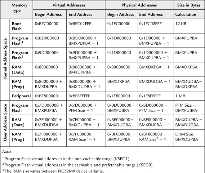
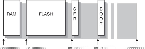
First, let’s find out where the main memory blocks (RAM and Flash memory) of the PIC32 are physically located inside the 32-bit addressing space (see Figure 6.7). Check the physical address column and you will find that RAM begins at address 0x00000000, and Flash memory begins at 0x1D000000. Finally, all peripherals (SFRs) are found in the block that begins at address 0x1F800000, and a 12 K portion of Flash memory is found at address 0x1FC00000 for use by a bootloader.
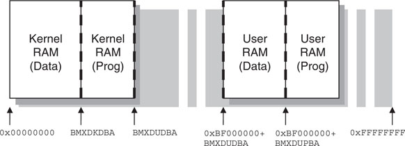
Access to those memory areas can be required for different purposes. The PIC32 designers wanted to make sure that we would be able to impose special “rules” to protect the applications from common (programming) errors isolating regions of memory. For example, when running an operating system (OS), we might desire to prevent application code to touch data (RAM) areas that are part of the OS. In other words, user code must not be allowed to access the kernel data. The BMX control unit is the one that performs the first layer of manipulation (see Figure 6.8). Through some of its control registers, we can split the main physical memory areas in slices of variable size. For example, using the BMXPUPBA register, we can split a portion of the Flash memory to be remapped for use only in user mode at physical address 0xBD000000 and higher. Similarly, RAM data memory can be split into four slices using the registers BMXDKPBA and BMXDUDBA, separating kernel data from user data memory and then splitting further each piece of memory for programs that want to execute from RAM to achieve higher performance; RAM maximum access speed is typically much higher than Flash memory, even when a cache mechanism is taken into account.
This is where the FMT (or more generically, an MMU) adds a new layer of complexity to the entire system, translating all physical addresses into virtual addresses and shuffling things around a bit. This is meant to create two widely separate address spaces where your programs can run: one for user applications in the lower half of the 32-bit addressing space (below 0x80000000) and one for kernel (above 0x80000000) in accordance with the standard practice of all MIPS-based processors. These correspond to the two halves of Table 6.1, where the first two columns show you the new virtual addresses assigned to each memory area in the corresponding mode.
Note
The only addresses the MPLAB C32 compiler and linker are concerned with, as seen in the early part of this chapter, are virtual addresses!
For clarity, Figure 6.9 illustrates the resulting virtual memory map as seen by an application program running in user mode.
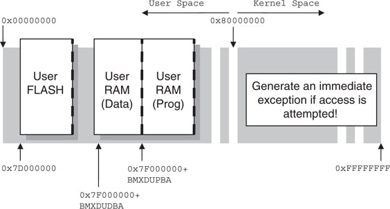
Notice how the Boot Flash memory is not mapped at all in user mode. There is no virtual address that will allow a user program to touch the protected area. No matter how bad, the code is running in user mode; it cannot harm the underlying operating system (or bootloader).
Similarly, notice how the peripherals (SFRs) don’t have a corresponding mapping in the user virtual address space. Again, no matter how bad the user code is, it cannot reach the hardware and modify or cripple the device configuration.
The Embedded-Control Memory Map
All this is nice and dandy if you are planning to run a heavyweight OS with all the bells and whistles, but in most embedded-control applications you will not use all these features. All your code will most likely always be running in kernel mode only, at the same level as an OS would. And even when you’re using an OS, you will find that most real-time operating systems (RTOSs) don’t use these features either, favoring speed of execution and efficiency over “protection.” This is a reasonable choice for embedded control. The application code is “well known”; it is supposed to be robust and well tested and should therefore be trusted!
This is great news because it means that from now on, we can completely ignore the bottom half of Table 6.1 and concentrate all our attention on only the kernel mode virtual map (see Figure 6.10)!
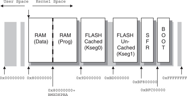
A final note is required to clarify the reason for two virtual address spaces being dedicated to the kernel program Flash memory. They are traditionally referred to as kseg0 and kseg1 in the MIPS literature. If you look at the Physical Addresses columns in Table 6.1, you will notice that eventually both point to the same physical memory space. The difference is only in the way the memory cache mechanism will manage the two virtual addresses. If a program is executing from the first virtual address space (kseg1), the memory cache is automatically disabled. Vice versa, portions of code that are placed in the kseg0 segment will be accessible by the cache mechanism. We will learn more in the next few chapters about the reason for this choice and the consequences for your code performance.
Debriefing
Today we have quickly reviewed the basics of string declaration and manipulation. We have also touched briefly on the use of pointers and dynamic memory allocation. We have seen how the .map file can help us identify where and how the memory of the PIC32 will be used by our applications. But today we have also explored the bus matrix module of the PIC32 and learned how it provides us with a very flexible mechanism to control the segmentation and access to blocks of Flash and RAM memory. Although many embedded-control applications will only use the most basic (default) configuration, the PIC32MX architecture offers a standard address space layout that makes it compatible with a wide range of tools and operating systems already available for the MIPS architecture.
Notes for the C Experts
In the C language, strings are defined as simple arrays of characters. The C language model has no concept of different memory regions (RAM vs. Flash). The const attribute is normally used in C language, together with most other variable types, only to assist the compiler in catching common parameter usage errors. When a parameter is passed to a function as a const or a variable is declared as a const, the compiler can in fact help flag any following attempt to modify it. The MPLAB C32 compiler extends this semantic in a very natural way, allowing us to provide hints to the compiler and linker to make more efficient use of the memory resources.
Notes for the Assembly Experts
The string.h library contains many block manipulation functions that can be useful, via the use of pointers, to perform operations on any type of data arrays, not just strings. They are:
The ctype.h library instead contains functions that help discriminate individual characters according to their positions in the ASCII table, to discriminate lowercase from uppercase, and/or to convert between the two.
Notes for the PIC Microcontroller Experts
Since the PIC32MX program memory is implemented using (single-voltage) Flash technology, programmable at run time during code execution, it is possible to design bootloader-based applications—that is, applications that automatically “update” part or all of their own code.
It is also possible to utilize a section of the Flash program memory as a nonvolatile memory (NVM) storage area. Some pretty basic limitations apply, though. For example, Flash memory can only be deleted in large blocks, called pages, composed of 1,024 words before data can be written one word at a time or in smaller blocks called rows composed of 128 words.
The PIC32 peripheral library comes to our assistance, offering a small set of functions (NVM.H) dedicated to the manipulation of on-chip Flash memory. Perhaps the most powerful function of the lot is NVMProgram(), capable of writing a block of arbitrary length to a given virtual address, automatically performing the necessary partitioning when page boundaries are crossed.
Tips & Tricks
String manipulation can be fun in C once you realize how to make the zero termination character work for you efficiently. Take, for example, the mycpy() function:
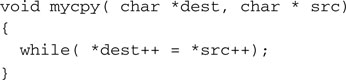
This is quite a dangerous piece of code, since there is no limit to how many characters could be copied, there is no check as to whether the dest pointer is pointing to a buffer that is large enough, and you can imagine what would happen should the src string be missing the termination character. It would be very easy for this code to continue beyond the allocated variable spaces and to corrupt the entire contents of the data memory. Ah, the power of pointers!
Soon we will explore the DMA module and we’ll discover its ability to share the PIC32 memory bus to perform fast data transfers between memory and peripherals. We’ll also explore using the DMA module to move large blocks of data between different memory buffers very efficiently. In fact, a few of the DMA functions in the PIC32 peripheral library are dedicated to the use of DMA channels to perform string and block manipulations, including DmaChnMemcpy(), DmaChnStrcpy(), and DmaChnStrncpy(). In the same set of functions can be found DmaChnMemCrc(), which does not transfer any data but feeds the CRC module with the contents of a given (no matter how large) block of data. Alternatively, a CRC calculation can automatically be performed during any block transfer performed by the DMA module by calling the CrcAttachChannel() function.
Exercises
You can develop new string manipulation functions to perform the following operations:
Books
Wirth, N., Algorithms+Data Structures=Programs (Prentice-Hall, Englewood Cliffs, NJ, 1976). With unparalleled simplicity, Wirth, the father of the Pascal programming language, takes you from the basics of programming all the way up to writing your own compiler. They tell me this book is no longer easy to find; however hard it might be to locate a copy, I promise you it will be worth the effort!
Links
http://en.wikipedia.org/wiki/Pointers#Support_in_various_programming_languages. Learn more about pointers and see how they are managed in various programming languages.