
Day 9 Asynchronous Communication
The Plan
Once you remove the clock line from the serial interface between two devices, what you obtain is an asynchronous communication interface. Whether you want full bidirectional (duplex) communication or just half-duplex (one direction at a time), multipoint, or point-to-point communication, there are many asynchronous protocols that can make communication possible and allow for efficient use of the media. In this lesson we will review the PIC32 asynchronous serial communication interface modules, UART1 and UART2, to implement a basic RS232 interface. We will develop a console library that will be handy in future projects for interface and debugging purposes.
Preparation
In addition to the usual software tools, including the MPLAB® IDE, the MPLAB C32 compiler, and the MPLAB SIM simulator, this lesson will require the use of the Explorer 16 demonstration board, your In-Circuit Debugger of choice, and a PC with an RS232 serial port (or a serial to USB adapter). You will also need a terminal emulation program. If you are using the Microsoft Windows operating system, the HyperTerminal application will suffice (Start|Programs | Accessories | Communication | HyperTerminal).
The Exploration
The UART interface is perhaps the oldest interface used in the embedded-control world. Some of its features were dictated by the need for compatibility with the first mechanical teletypewriters. This means that at least some of its technology has centuries’-old roots.
On the other hand, nowadays finding an asynchronous serial port on a new computer (and especially on a laptop) is becoming a challenge. The serial port has been declared a “legacy interface,” and for several years now, strong pressure has been placed on computer manufacturers to replace it with the USB interface. Despite the decline in their popularity and the clearly superior performance and characteristics of the USB interface, asynchronous serial interfaces are strenuously resisting in the world of embedded applications because of their great simplicity and extremely low cost of implementation.
Four main classes of asynchronous serial application are still being used:
The PIC32’s UART modules can support all four major application classes and packs a few more interesting features, too.
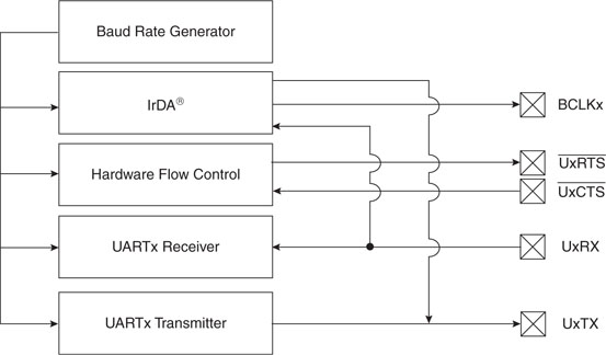
To demonstrate the basic functionality of a UART peripheral, we will use the Explorer16 demo board where the UART2 module is connected to an RS232 transceiver device and to a standard 9 poles D female connector. This can be connected to any PC serial port or, in absence of the “legacy interface” as mentioned above, to an RS232 to USB converter device. In both cases the Windows HyperTerminal program will be able to exchange data with the Explorer16 board with a basic configuration setting.
The first step is the definition of the transmission parameters. The options include:
For our demo we will choose the fast and convenient configuration:115200, 8, N, 1, CTS/RTS—that is:
UART Configuration
Use the New Project Setup checklist to create a new project called Serial and a new source file, similarly called serial.c. We will start by adding a few useful I/O definitions to help us control the hardware handshake lines:
The hardware handshake is especially necessary in communicating with a Windows terminal application, since Windows is a multitasking operating system and its applications can sometimes experience long delays that would otherwise cause significant loss of data. We will use one I/O pin as an input (RF12 on the Explorer 16 board) to sense when the terminal is ready to receive a new character (Clear To Send), and one I/O pin as an output (RF13 on the Explorer 16 board) to advise the terminal when our application is ready to receive a character (Request To Send).
To set the baud rate, we get to play with the Baud Rate Generator (U2BREG), a 16-bit counter that feeds on the peripheral bus clock. From the device datasheet we learn that in the normal mode of operation (BREGH=0) it operates off a 1:16 divider versus a highspeed mode (BREGH=1) where its clock operates off a 1:4 divider. A simple formula, published on the datasheet, allows us to calculate the ideal setting for our configuration (see Equation 9.1).
Equation 9.1. UART Baud Rate with UxBREG = 1.
In our case, Equation 9.1 translates to the following expression:
U2BREG = (36,000,000/4/115,200) – 1 = 77.125
To decide how to best round out the result, we need a 16-bit integer after all. We will use the reverse formula to calculate the actual baud rate and determine the percentage error:
Error = ((Fpb/4/(U2BREG+1)) – baud rate)/baud rate %
Rounding up to a value of 77, we obtain an actual baud rate of 115,384 baud with an error of just 0.2 percent—well within acceptable tolerance. However, with a value of 78 we obtain 113,924 baud, a larger 1.1 percent error but still within the acceptable tolerance range for a standard RS232 port (±2 percent).
We can therefore define the constant BRATE as:
![]()
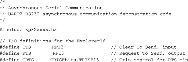
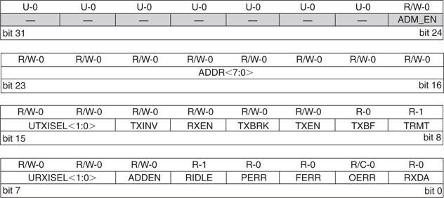
Two more constants will help us define the initialization values for the UART2 main control registers called U2MODE and U2STA (see Figure 9.2).
The initialization value for U2MODE will include the BREGH bit, the number of stop bits, and the parity bit settings.
![]()
The initialization for U2STA will enable the transmitter and clear the error flags (see Figure 9.3 ):
![]()
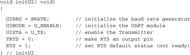
Using the constants defined above, let’s initialize the UART2module, the baud rate generator, and the I/O pins used for the handshake:
Sending and Receiving Data
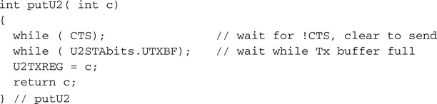
Sending a character to the serial port is a three-step procedure:
All of the above can be nicely packaged in one short function that we will call putU2(), respecting a rule that wants all C language I/O libraries (stdio.h) to use the put – prefix to offer a series of character output functions such as putchar(), putc(), fputc() and so on:
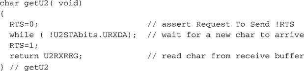
To receive a character from the serial port, we will follow a very similar sequence:
Again, all of the above steps can be nicely packaged in one last function:
Testing the Serial Communication Routines
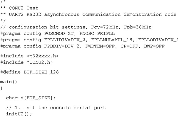
To test our serial port control routines, we can now write a small program that will initialize the serial port, send a prompt, and let us type on the terminal keyboard while echoing each character back to the terminal screen:
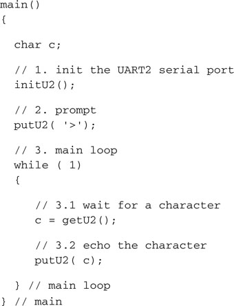
Note
I recommend, for now, that you do not attempt to single-step or use breakpoints or the RunToCursor function when using the UART! See the “Tips & Tricks” section at the end of the chapter for a detailed explanation.
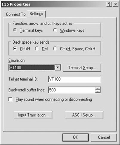
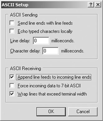
If HyperTerminal is already set to provide an echo for each character sent, you will see double—literally! To disable this functionality, first hit the Disconnect button on HyperTerminal. Then select File | Properties to open the Properties dialog box, and select the Settings Pane tab (see Figure 9.4). This will be a good opportunity to set a couple more options that will come in handy in the rest of the exploration.
Building a Simple Console Library
To transform our demo project in a proper terminal console library that could become handy in future projects, we need only a couple more functions that will complete the puzzle: a function to print an entire (zero-terminated) string and a function to input a full text line. Printing a string is, as you can imagine, the simple part:
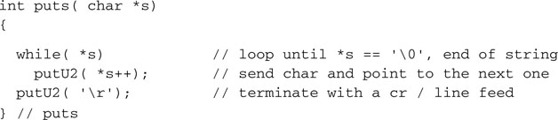
It is just a loop that keeps calling the putU2() function to send, one after the other, each character in the string to the serial port.
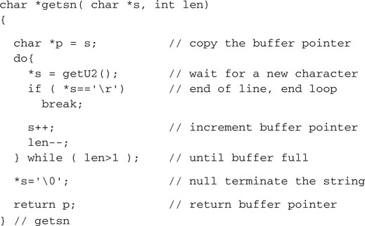
Reading a text string from the terminal (console) into a string buffer can be equally simple, but we have to make sure that the size of the buffer is not exceeded (should the user type a really long string), and we have to convert the carriage return character at the end of the line in a proper � character for the string termination:
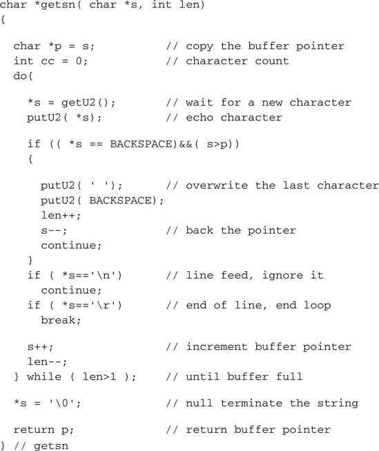
In practice, the function as presented would prove very hard to use. There is no echo of what is being typed, and the user has no room for error. Make only the smallest typo and the entire line must be retyped. If you’re like me, you make a lot of typos all the time, and the most battered key on your keyboard is the Backspace key. A better version of the getsn() function must include character echo and at least provisions for the Backspace key to perform basic editing. It really takes only a couple more lines of code. The echo is quickly added after each character is received. The Backspace character (identified by the ASCII code 0x8) is decoded to move the buffer pointer one character backward (as long as we are not at the beginning of the line already). We must also output a specific sequence of characters to visually remove the previous character from the terminal screen:
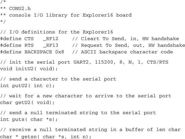
Put all the functions in a separate file that we will call conU2.c. Then create a small header file conU2.h, to decide which functions (prototypes) and which constants to publish and make visible to the outside world:
Testing a VT100 Terminal
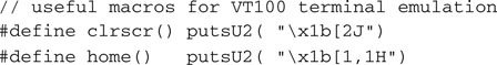
Since we have enabled the VT100 terminal emulation mode (see the previous HyperTerminal settings), we now have a few commands available to better control the terminal screen and cursor position, such as:
These commands are performed by sending so-called “escape sequences,” defined in the ECMA-48 standard (also ISO/IEC 6429 and ANSI X3.64), also referred to as ANSI escape codes. They all start with the characters ESC (ASCII 0x1b) and the character [ (left square bracket).
To test the console library we can now write a small program that will:
Save the following code in a new file that we will call CONU2test.c:
The Serial Port as a Debugging Tool
Once you have a small library of functions to send and receive data to a console through the serial port, you have a new powerful debugging tool available. You can strategically position calls to print functions to present the content of critical variables and other diagnostic information on the terminal. You can easily format the output to the most convenient format for you to read. You can add input functions to set parameters that can help better test your code, or you can use the input function to simply pause the execution and give you time to read the diagnostic output when required. This is one of the oldest debugging tools, effectively used since the first computer was invented and connected to a teletypewriter.
The Matrix Project
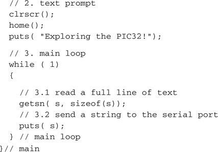
To finish today’s exploration on a more entertaining note, let’s develop a new demo project that we will call the matrix. The intent is that of testing the speed of the serial port and the PC terminal emulation by sending large quantities of text to the terminal and clocking its performance. The only problem is that we don’t (yet) have access to a large storage device from which to extract some meaningful content to send to the terminal. So the next best option is that of “generating” some content using a pseudo-random number generator. The stdlib.h library offers a convenient rand() function that returns a positive integer between 0 and RAND_MAX (which, in the MPLAB C32 implementation, can be verified to be equal to the largest signed 32-bit integer available).
Using the “reminder of” operator (denoted by the % symbol in C language), we can reduce its output to any smaller integer range and, in our example, produce a subset of values that corresponds to ASCII printable characters only. The following statement, for example, will produce only characters in the range from 33 to 127:
![]()
To generate a more appealing and entertaining output, especially if you happened to watch the movie The Matrix, we will present the (random) content by columns instead of rows. We will use the pseudo-random number generator to change the content and the “length” of each column as we periodically redraw the entire screen:
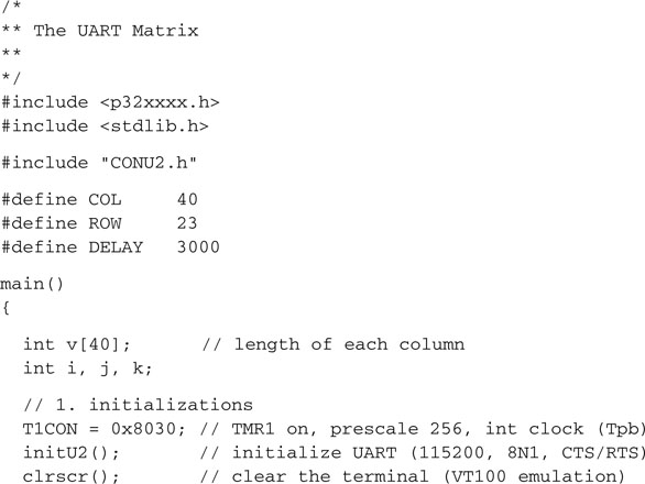
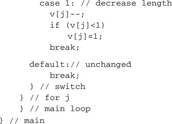
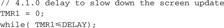
Forget the performance—watching this code run is fun. It is too fast anyway; in fact, you will have to add a small delay loop (inside the for loop in 4.1) to make it more pleasing to the eye:
Note
Remember to take the blue pill next time!
Debriefing
In this lesson we developed a small console I/O library while reviewing the basic functionality of the UART module for operation as an RS232 serial port. We connected the Explorer 16 board to a VT100 terminal (emulated by Windows HyperTerminal). We will take advantage of this library in the next few lessons to provide us with a new debugging tool and possibly as a user interface for more advanced projects.
Notes for the C Experts
I am sure that, at this point, you are wondering about the possibility of using the more advanced library functions defined in the stdio.h library, such as printf(), to direct the stdout output stream to the UART2 peripheral. Not only is this possible, but you can consider it done!
In addition, the stdio.h library defines two helper functions, _mon_putc() and _mon_ getc(), that can be used to customize the behavior of the standard library. They are declared with the attribute weak, which means that the MPLAB C32 linker won’t complain about you trying to redefine them. In fact, you are supposed to redefine them in order to implement new functionalities, such as using the SPI port as your input/output stream or redirecting the output to an LCD display and so on.
Note
Remember that whether you customize the stdio.h functions or not, you are always responsible for the proper interface initialization. So before the first call to printf(), make sure the UART2 or your communication peripheral of choice is enabled and the baud rate is set correctly.
Notes for the PIC® Microcontroller Experts
Sooner or later, every embedded control designer will have to come to terms with the USB bus. If, for now, a small “dongle” (converting the serial port to a USB port) can be a reasonable solution, eventually you will find opportunities and designs that will actually benefit from the superior performance and compatibility of the USB bus. Several 8- and 16-bit PIC microcontroller models already incorporate a USB Serial Interface Engine (SIE) as a standard communication interface. Microchip offers a free USB software stack with drivers and ready-to-use solutions for the most common classes of application.
One of them, known as the Communication Device Class (CDC), makes the USB connection look completely transparent to the PC application so that even HyperTerminal cannot tell the difference. Most important, you will not need to write and/or install any special Windows drivers. When writing the application in C, you won’t even notice the difference, if not for the absence of a need to specify any communication parameter. In USB there is no baud rate to set, no parity to calculate, no port number to select (incorrectly), and the communication speed is so much higher …
Tips & Tricks
As we mentioned during one of the early exercises presented in this lesson, single-stepping through a routine that enables and uses the UART to transmit and receive data from the HyperTerminal program is a bad idea. You will be frustrated seeing the HyperTerminal program misbehave and/or simply lock up and ignore any data sent to it without any apparent reason.
To understand the problems, you need to know more about how the MPLAB ICD2 in circuit debugger operates. After executing each instruction when in single-step mode or upon encountering a breakpoint, the ICD2 debugger not only stops the CPU execution but also “freezes” all the peripherals. It freezes them, as in dead-cold-ice all of a sudden; not a single clock pulse is transmitted through their digital veins. When this happens to a UART peripheral that is busy in the middle of a transmission, the output serial line (TX) is also frozen in the current state. If a bit was being shifted out in that precise instant, and specifically if it was a 1, the TX line will be held in the “break” state (low) indeterminately. The HyperTerminal program, on the other side, would sense this permanent “break” condition and interpret it as a line error. It will assume that the connection is lost and it will disconnect. Since HyperTerminal is a pretty “basic” program, it will not bother letting you know what is going on; it will not send a beep, not an error message, nothing—it will just lock up!
If you are aware of the potential problem, this is not a big deal. When you restart your program with the ICD2, you will only have to remember to click the HyperTerminal Disconnect button first and then the Connect button again. All operations will resume normally.
Exercises
Books
Axelson, J., Serial Port Complete, second edition (Lakeview Research, Madison, WI, 2007 ). This new edition was published just in time for me to include it here. The author is most famous for her USB Complete” book (see below), considered the reference book for all embedded-control programmers. Over time she has developed and maintained a whole series completely dedicated to serial and parallel communication interfaces.
Axelson, J., USB Complete, third edition (Lakeview Research, Madison, WI, 2005). By the time you read this book, most probably new models of the PIC32MX family will have been announced offering USB communication capabilities. So, I thought you might appreciate this recommendation. Jan Axelson’s book has reached the third edition already. She has continued to add material at every step and still managed to keep things very simple.
Eady, F., Implementing 802.11 with Microcontrollers: Wireless Networking for Embedded Systems Designers ( Newnes, Burlington, MA, 2005 ). Fred brings his humor and experience in embedded programming to make even wireless networking seem easy.
Links
http://en.wikipedia.org/wiki/ANSI_escape_code. This is a link to the complete table of ANSI escape codes as implemented by the VT100 HyperTerminal emulation.
www.cs.utk.edu/~shuford/terminal/dec.html. This is a real dive into a piece of the history of computers. I used these terminals; does this make me look old?