
Day 10 Glass = Bliss
The Plan
I would be surprised if you told me that on your desk next to your PC there was still a large and bulky CRT computer monitor. In a matter of a few years the entire personal computer industry has shifted to the new technology: flat LCD panels of ever larger size and higher resolution. In the embedded-control world, something similar has happened. LED seven-segment displays are so 1990s! Small LCD displays have become ubiquitous and, besides consuming a fraction of the power of their LED counterparts, they provide alphanumeric output (i.e., they support text) and, ever more often, graphics as well. But wait, maybe there is already another generation of organic LED displays (OLEDs) just around the corner and ready to demand revenge.
In this lesson, we will learn how to interface with a small and inexpensive LCD alphanumeric display module. This project will be a good excuse for us to learn and use the Parallel Master Port (PMP), a flexible parallel interface available on all PIC32MX microcontrollers.
Preparation
In addition to the usual software tools, including the MPLAB® IDE, the MPLAB C32 compiler, and the MPLAB SIM simulator, this lesson will require only the use of the Explorer 16 demonstration board and your In-Circuit Debugger of choice (PIC32 Starter kit, ICD2, REAL ICE, or the like).
The Exploration
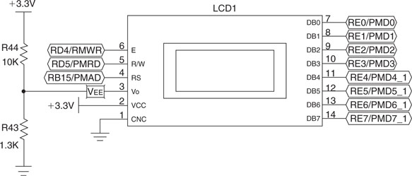
The Explorer 16 board can accommodate three different types of dot-matrix, alphanumeric LCD display modules and one type of graphic LCD display module. By default, it comes with a simple “2-rows by 16-character” display and a 3V alphanumeric LCD module (most often a Tianma TM162JCAWG1) compatible with the industry-standard HD44780 controllers. These LCD modules are complete display systems composed of the LCD glass, column, and row multiplexing drivers; power supply circuitry; and an intelligent controller, all assembled together in so-called Chip On Glass (COG) technology. Thanks to this high level of integration, the circuitry required to control the dot-matrix display is greatly simplified. Instead of the hundreds of pins required by the column-and-row drivers to directly control each pixel, we can interface to the module with a simple 8-bit parallel bus using just 11 I/Os.
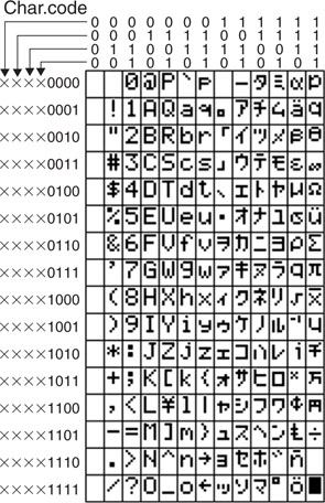
On alphanumeric modules (see Figure 10.1) in particular, we can directly place ASCII character codes into the LCD module controller RAM buffer (known as the Display Data RAM buffer, or DDRAM). The output image is produced by an integrated character generator (a table) using a 5 × 7 grid of pixels to represent each character. The table (see Figure 10.2) typically contains an extended ASCII character set in the sense that it has been somewhat merged with a small subset of Japanese Kata Kana characters as well some symbols of common use. While the character generator table is mostly implemented in the display controller ROM, various display models offer the possibility to extend the character set by modifying/creating new characters (from 2 to 8) accessing a second small internal RAM buffer (the Character Generator RAM buffer, or CGRAM).
HD44780 Controller Compatibility
As mentioned, the 2 × 16 LCD module used in the Explorer 16 board is one among a vast selection of LCD display modules available on the market in configurations ranging from 1 to 4 lines of 8, 16, 20, 32, and up to 40 characters each and that are compatible with the original HD44780 chipset, today considered an industry standard.
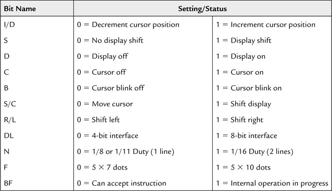
The HD44780 compatibility means that the integrated controller contains just two separately addressable 8-bit registers: one for ASCII data and one for commands/status. The standard sets of commands shown in Tables 10.1 and 10.2 can be used to set up and control the display.
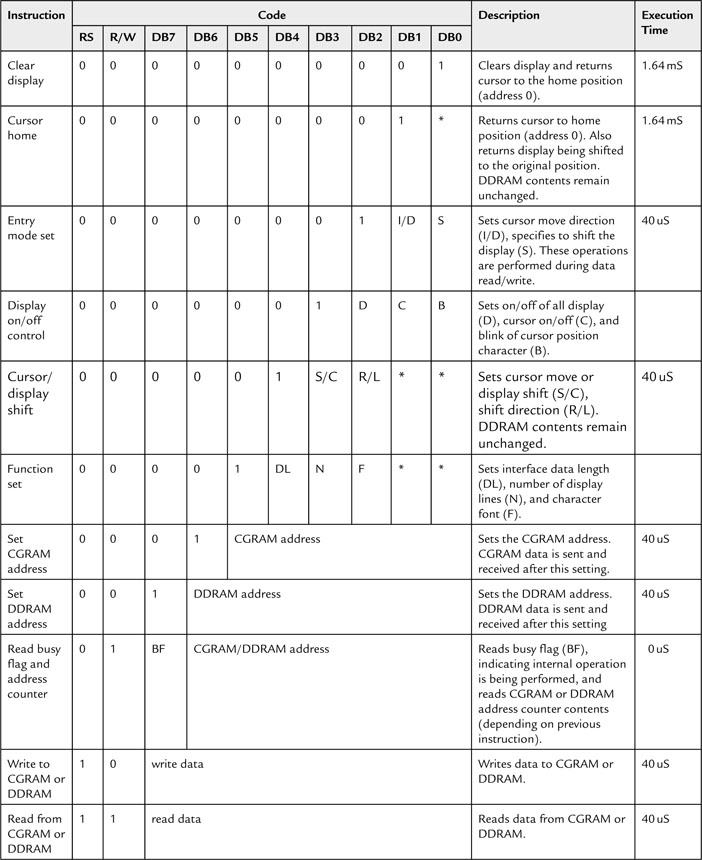
Thanks to this commonality, any code we will develop to drive the LCD on the Explorer 16 board will be immediately available for use with any of the other HD44780-compatible alphanumeric LCD display modules.
The Parallel Master Port
The simplicity of the 8-bit bus shared by all these display modules is remarkable. Beside the eight bidirectional data lines (which, by enabling a special “nibble” mode, could be reduced to just four for further I/O saving), there is:
It would be simple enough to control the 11 I/Os by accessing manually (bit banging) the individual PORTE and PORTD pins to implement each bus sequence, but we will take this opportunity instead to explore the capabilities of a new peripheral introduced with the PIC24 architecture and enhanced in the PIC32 architecture: the Parallel Master Port (PMP). This addressable parallel port was designed to ease access to a large number of external parallel devices of common use, ranging from analog-to-digital converters, RAM buffers, ISA bus compatible interfaces, LCD display modules, and even hard disk drives and Compact Flash cards.
You can think of the PMP as a sort of flexible I/O bus added to the PIC32 architecture that relieves the microcontroller of the mundane task of managing slow external peripherals. The PMP offers:
The PMP can also be configured to operate in slave mode to attach, as an addressable peripheral, to a larger microprocessor/microcontroller system.
Both bus read and bus write sequences are fully programmable so that not only can the polarity and choice of control signals be configured to match the target bus, the timing can also be finely tuned to adapt to the speed of the peripherals to which we want to interface.
Configuring the PMP for LCD Module Control
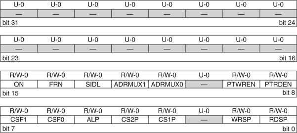
As in all other PIC32 peripherals, there is a set of control registers dedicated to the PMP configuration. The first and most important one is PMCON. You will recognize the familiar sequence of control bits common to all the modules xxCON registers (see Figure 10.3).
The list of control registers that we will need to initialize is a bit longer this time and also includesPMMODE, PMADDR, PMSTAT, and PMAEN. They are packed with powerful options and they all require your careful consideration. Instead of proceeding through a lengthy review of each and every one of them, I will list only the key choices required specifically by the LCD module interface:
Also, considering that the typical LCD module is an extremely slow device, we will better select the most generous timing, adding the maximum number of wait states allowed at each phase of a read or write sequence:
A Small Library of Functions to Access an LCD Display
Create a new project called Liquid using the New Project checklist and a new source file liquid.c to start creating a small LCD interface library.
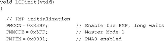
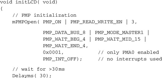
We will start writing the LCD initialization routine first. It is natural to start with the initialization of the PMP port key control registers:
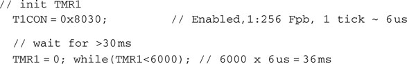
After these steps, we are able to communicate with the LCD module for the first time, and we can follow a standard LCD initialization sequence as recommended by the manufacturer. The initialization sequence must be timed precisely (see the HD44780 instruction set for details) and cannot be initiated before at least 30 ms have been granted to the LCD module to proceed with its own internal initialization (power on reset) sequence. For simplicity and safety, we will hardcode a delay in the LCD module initialization function, and we will use the Timer1 module to obtain simple but precise timing loops for all subsequent steps:
For our convenience, we will also define a couple of constants that will hopefully help us make the following code more readable:
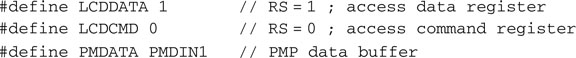
To send each command to the LCD module, we will select the command register (setting the address PMA0 = RS = 0) first. (see Figure 10.4).
Then we will start a PMP write sequence by depositing the desired command byte in the PMP data output buffer:
![]()
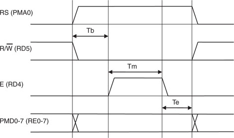
The PMP will perform the complete bus write sequence as follows:
Notice how this sequence is quite long as it extends for 20 X Tpb or more than 0.5 us after the PIC32 has initiated it. In other words, the PMP will still be busy executing part of this sequence while the PIC32 will have already executed at least another 40 instructions or more. Since we are going to wait for a considerably longer amount of time anyway (>40 us) to allow the LCD module to execute the command, we will not worry about the time the PMP requires to complete the command; we’ll just have to wait patiently.
![]()
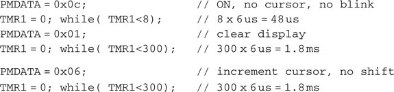
We will then proceed similarly with the remaining steps of the LCD module initialization sequence:
After the LCD module initialization, things will get a little easier and the timing loops will no longer be necessary, because we will be able to use the LCD module Read Busy Flag command. This will tell us whether the integrated LCD module controller has completed the last command and is ready to receive and process a new one. To read the LCD status register containing the LCD busy flag, we will need to instruct the PMP to execute a bus read sequence. This is a two-step process: First, we initiate the read sequence by reading (and discarding) the contents of the PMP data buffer (PMPDIN) a first time. When the PMP sequence is completed, the data buffer will contain the actual value read from the bus, and we will read its contents from the PMP data buffer again. But how can we tell when the PMP read sequence is complete?
Simple: We can check the PMP busy flag (PMMODEbits.BUSY) in the PMMODE control register (see Figure 10.5).
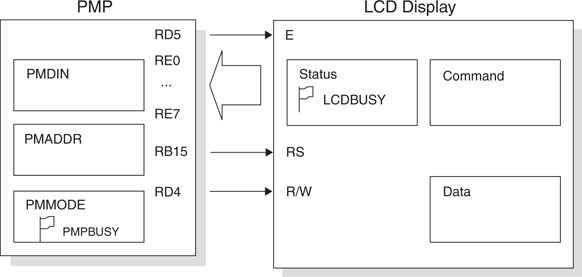
In summary, to check the LCD module busy flag, we will need to check the PMP busy flag first to make sure that any previous command is completed, issue a read command, wait for the PMP busy flag again, and only at this point will we gain access to the actual LCD module status register contents, including the LCD busy flag.
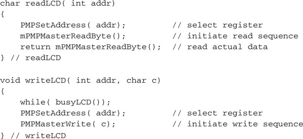
By passing the register address as a parameter to the read function, we will obtain a more generic function that will be able to read the LCD status register or the data register, as in the following code:
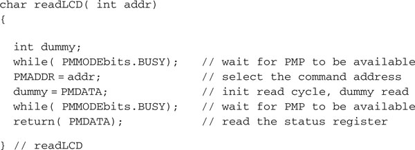
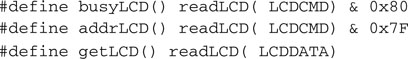
The LCD module status register contains two pieces of information: the LCD busy flag and the LCD RAM pointer current value. We can use two simple macros, busyLCD() and addrLCD(), to split the two pieces and a third one, getLCD(), to access the data register:
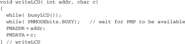
Using the busyLCD() function we can create a function to write data or commands to the LCD module:
A few additional macros will help complete the library:
![]()
![]()
![]()
![]()
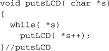
And finally, for our convenience, we might want to add putsLCD(), a function that will send an entire null terminated string to the display module:
Let’s put all of our work together, adding a short main function:
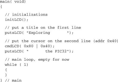
If all went well, after building the project and programming the Explorer 16 board with the debugger of choice, you will now have the great satisfaction of seeing the title string showing, split between the two rows of the LCD display.
Building an LCD Library and Using the PMP Library
The exact same functionality can be obtained using the specific PMP peripheral library by including the pmp.h library or simply including plib.h. Four functions in particular provide us with all the tools we need to control the PMP and dialog with the LCD display:
Since we are at it, we will not only rewrite the code to use the more descriptive macros and definitions offered by the library, we will also rearrange the code a little so to transform it into a practical little library of its own to be used in the near future in other projects with the Explorer 16 demonstration board.
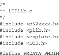
Let’s start by creating a new project that we will call LCD library. Then let’s create a new source file called LCDlib.c. Here is the new initLCD() function as expressed using the PMP library functions and macros:
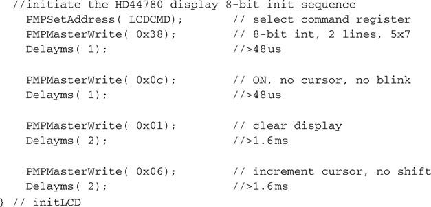
Notice how I exaggerated the timing delays in the initialization sequence in order to use a single delay function that operates in basic increments of 1 millisecond called Delayms(). We will see shortly how and where to define it.
Here are the other core functions that will populate our simple LCD library:
If you found in the previous project (Liquid) that setting the cursor on the second line of the display was a bit awkward, you will agree that adding a little smarts to the putsLCD() function could be helpful. In particular, it would be nice to allow the routine to interpret a few special characters, like the line end, tab, and the new line, similarly to the way a serial port and/or a console are expected to.
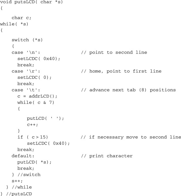
This way, printing a string containing (or terminating) with the character (new line) will set the cursor to the beginning of the second line of the LCD display. A character (line end) will place the cursor back to the beginning of the first line, and character (tab) will produce the expected result.
A standard header and a few #include statements will complete the module:
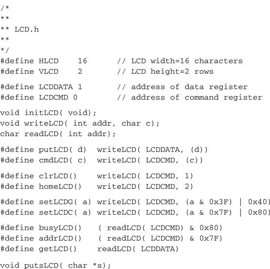
Save the LCDlib.c code file we just completed and then start a new source file in the MPLAB editor window. This will be the include file LCD.h, which will complete the library by publishing all the macros and function prototypes required:
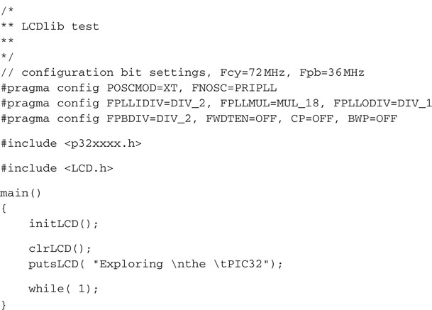
Finally, to test the newly created LCD library, let’s write a small new test program that we will call LCDlib test.c:
THE EXPLORER.C LIBRARY
To help us initialize the PIC32 for maximum performance (see Day 7), vectored interrupts (see Day 5) and use the features offered by the Explorer16 board (such as the LED bar, see Day 1–3), at this point, we should start aggregating in a new small library a couple of handy functions. We will keep adding gradually new functions to it in the next few chapters but here is its first incarnation:
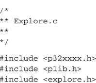
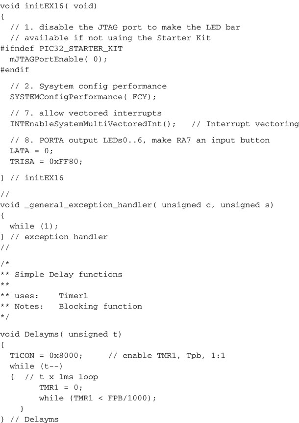
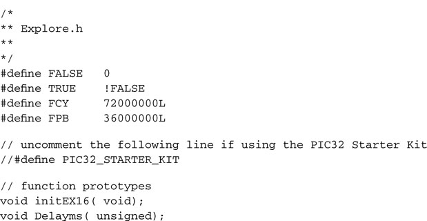
The corresponding include file: explore.h will gather as well some useful definitions and the first two functions’ prototypes:
Creating the include and lib Directories
To keep our files in order and our projects clean and tidy, we should apply a little discipline here and start grouping all the simple libraries we created so far two subdirectories:
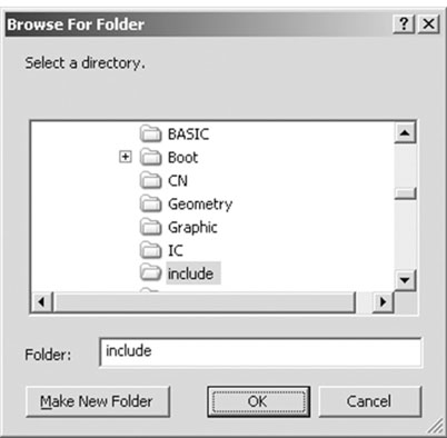
From now on we will refer automatically to these modules by adding the include directory to the include search path of each new project. The sequence of steps required will be the following:
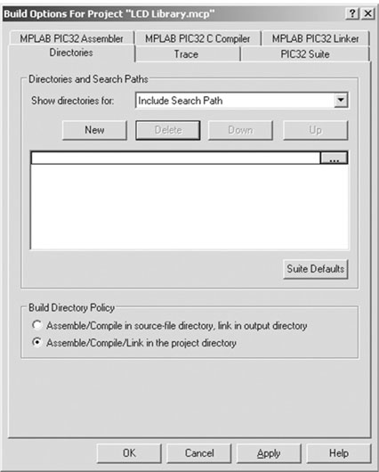
With these settings, we will be able to refer to the LCD.h file with the default include statement, as in:
![]()
without needing to add details of the path required to reach the directory where the file is actually stored.
Note
Notice the use of the angled brackets (<>) as opposed to the double quotes (“ ”) syntax. The difference between the two notations lies in where the compiler will look for the file to be included. The double quotes method we used in all previous projects tells the compiler to look for a file inside the current project directory. The angled brackets, on the other hand, tell the compiler to look for the file inside a series of directories known as the include search path that typically contains all the compiler-specific (MPLAB C32) library directories defined during the installation of the program on our computer but also all the additional directories we listed in the Include Search Path dialog box.
Advanced LCD Control
If you felt that the preceding discussion was not too complex or perhaps not rewarding enough, here we have some more interesting stuff and a new challenge for you to consider.
When we introduced the HD44780 compatible alphanumeric LCD modules, we mentioned how the display content was generated by the LCD module controller using a table, the character generator, located in ROM. But we also mentioned the possibility to extend the character set with user-defined symbols using an additional RAM buffer (known as the CGRAM). Writing to the CGRAM, it is possible to create from two to eight new character patterns, depending on the LCD display model. Of course, if we had 32 user-defined characters, we could almost turn the entire alphanumeric display into a complete graphical display. Unfortunately, the most popular and inexpensive LCD modules, in particular the ones used on the Explorer 16 board, have only space for two user-defined characters. Still, there are a number of interesting things we can do with those. In the following, for example, we use just one of the two user-defined characters to illustrate how to develop a simple progress bar effect.
We will need a function to set the LCD module RAM buffer pointer to the beginning of the CGRAM area using the Set CGRAM Address command, or better a macro that uses the writeLCD() function:
![]()
Once the buffer pointer is set on the CGRAM and specifically at the beginning of the buffer (setLCDG( 0) ), we can use the putLCD() function to place 8 bytes of data in the buffer. Each byte of data will contribute 5 bits (LSb) to the construction of the eight rows composing the new character pattern. After repositioning the buffer pointer into the DDRAM area (using the macro setLCDC( 0) ), we can use the newly defined character with the ASCII code 0x00.
Notice that by convention, although the first line of the display corresponds to addresses from 0 to 15 of the DDRAM buffer, the second line is always found at addresses from 0x40 to 0x4f independently of the display width—the number of characters that compose each line of the actual display.
Progress Bar Project
It is time to start our last project for the day. We’ll call it Progress. Let’s proceed with the usual New Project checklist, and remember at the end to add the include directory in the include search path.
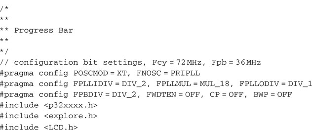
A new source file, ProgressBar.c, can be immediately created by inserting the standard template and include statements list:
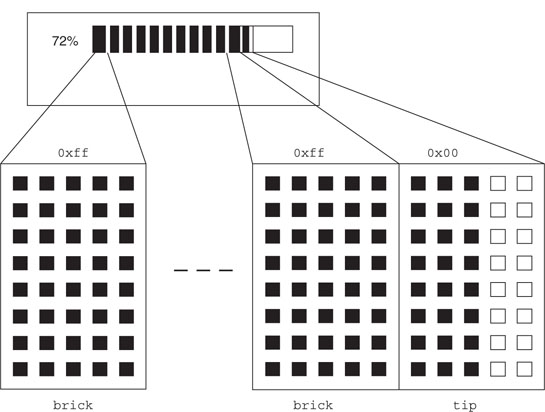
We could draw a blocky progress bar using just a string of (up to) 16 “brick” characters that can be obtained from the LCD font table by selecting the code 0xff, giving a solid 5 × 8 black pixels pattern. But to obtain a finer resolution and smoother motion, we can exploit instead the user-defined character feature we just learned to use. The trick is to build most of the progress bar with (5 × 8) bricks and then define a single new character of the required thickness for the tip (see Figure 10.8).
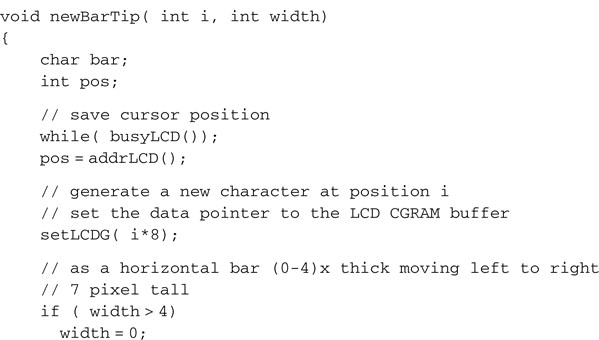
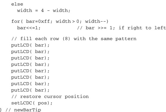
Here is the code required to define a progress bar tip of given thickness:
Given this essential building block, drawing an actual progress bar requires only a few more lines of code:
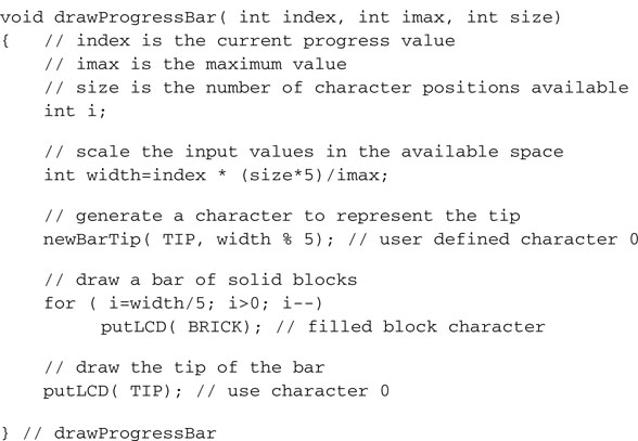
As you can see, to make the drawProgressBar() function really friendly, I included a little scaling of the input values so that the bar itself can be made to fit the desired number of spaces on the LCD display and the progress level is made relative to a given maximum value passed as a parameter. To put it to the test, we’ll define a loop where a counter value (index) is cycling slowly through a range of values from 0 to 99. Each value is shown in the first three characters of the first line of the display. The rest of the line is filled with the progress bar.
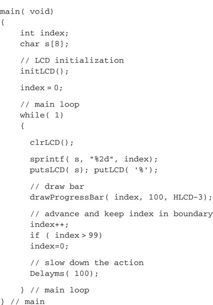
Notice that it is important to slow the execution of the main loop by inserting a small delay; otherwise the refresh of the display is so rapid that all we get to see is a sort of ghostly faint image. Remember, LCD displays are slow little things; be patient with them!
Finally, before you start building the project, remember to add all the required library modules we used. You will need to select the project window and right-click the source files to Add file. Browse to the lib directory we created today and select both the explore.c module (that will give us the Delayms() function) and the LCDlib.c module.
Now build the project, program the Explorer 16 board with the debugger of your choice, and observe the code running and drawing a progress bar that moves smoothly from left to right to fill the entire top line of the LCD display. This is true (glass) bliss!
Debriefing
Today we learned how to use the Parallel Master Port to interface to an alphanumeric LCD display module, just one of many common devices that require an 8-bit parallel interface. Since the LCD display modules are relatively slow peripherals, it might seem that there has been little or no significant advantage in using the PMP instead of a traditional bit-banged I/O solution. In reality, even when accessing such simple and slow peripherals, the use of the PMP can provide two important benefits:
Notes for the PIC24 Experts
The PMP module of the PIC32 is mostly identical to the PIC24 peripheral, yet some important enhancements have been included in its design. Here are the major differences that will affect your code while porting an application to the PIC32:
Tips & Tricks
Though basic alphanumeric displays are pretty much standardized around the HD44780 controller interface and command set, things are very different when it comes to graphic displays. A variety of controllers are being currently offered with very different capabilities. The most common controllers for small LCD displays are probably the New Japan Radio (NJU6679) used in many monochrome displays (up to 128 × 128) and using a parallel interfaces very similar to the HD44780. But the new trend is represented by the serially interfaced EPSON ( S1D15G10 ) controllers used in many inexpensive color LCD displays, often referred to as “Nokia knock-offs” because their low price is mostly driven by the large volumes of production supposedly achieved on the latest generations of multimedia phones. OLED displays are also going the way of the serial interfaces (SPIs). Finally, when the resolution of the display grows beyond the QVGA (320*240), you can no longer rely on finding a complete controller chip on glass, and you have to start producing a complex synchronized waveform while continuously refreshing the screen. A QVGA or more advanced display peripheral module becomes a necessity.
Exercises
Books
Bentham, Jeremy, TCP/IP Lean: Web Servers for Embedded Systems (CMP Books, Lawrence, KS).This book will take you one level of complexity higher, showing you how the TCP/IP protocols, the foundation of the Internet, can be easily implemented in a “few” lines of C code. The author knows how to keep things “lean” as necessary in every embedded-control application.
Links
www.microchip.com/graphics. Microchip is offering graphic libraries capable of supporting the most popular LCD display controllers for the 16-bit and 32-bit architectures. Check the availability of free and third-party supported libraries on the Web Graphic Design Center. www.microchip.com/stellent/idcplg?IdcService=SS_GET_PAGE&nodeId=1824&appnote=en011993. This is a link to Microchip Application Note 833, a free TCP/IP stack for all PICmicros. www.microchip.com/stellent/idcplg?IdcService=SS_GET_PAGE&nodeId=1824&appnote=en012108. Application Note 870 describes a Simple Network Management Protocol for Microchip TCP/IP stack-based applications.