
Day 15 File I/O
The Plan
Just yesterday, we developed a basic interface module (both software and hardware) to gain access to an SD/MMC card and support applications that require large amounts of data storage. A similar interface could be built for several other types of mass storage media, but in this lesson we will instead focus on the algorithms and data structures required to properly share information on the mass storage device with the most common PC operating systems (DOS, Windows, and some Linux distributions). In other words, we will develop a module for access to a standard file system known commonly as FAT16.
The first FAT file system was created by Bill Gates and Marc McDonald in 1977 for managing disks in Microsoft Disk BASIC. It used techniques that had been available in file systems many years before that, and it has continued to evolve in numerous versions over the last few decades to accommodate ever larger-capacity mass storage devices and new features. Among the many versions still in use today, the FAT12, FAT16, and FAT32 are the most common ones. FAT16 and FAT32, in particular, are recognized by practically every PC operating system currently in use; the choice between the two is mostly dictated by efficiency considerations and the capacity of the media. Ultimately, for most Flash mass storage devices of common use in consumer multimedia applications, FAT16 is the file system of choice.
Preparation
Today’s exploration continues using the hardware platform used in the previous chapter. You will need an Explorer 16 or equivalent demo board with an additional expansion board or prototyped circuit to connect an SD card connector and a few pull-up resistors. Check the companion Web site at www.exploringPIC32.com for a list of expansion options available to facilitate the experiments presented in this chapter.
The Exploration
The term FAT is an acronym for File Allocation Table, which is also the name of one of the most important data structures used in this file system. After all, a file system is just a method for storing and organizing computer files and the data they contain to make it easy to find and access them. Unfortunately, as often is the case in the history of personal computing, standards and technologies are the fruit of constant evolutionary progress rather than original creation. For this reason many of the details of the FAT file system we will reveal in the following discussion can only be explained in the context of a struggle to continue and maintain compatibility with an enormous mass of legacy technologies and software over many years.
Sectors and Clusters
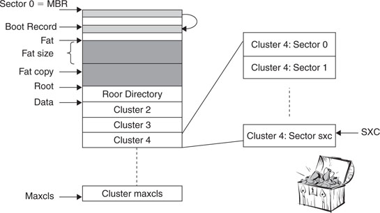
Still, the basic ideas at the root of a FAT file system are quite simple. As we saw in the previous lesson, most mass storage devices follow a “tradition” derived from the hard disk technology of managing memory space in blocks of a fixed size, 512 bytes, commonly referred to as sectors. In a FAT file system, a small number of these sectors are reserved and used as a sort of general index: the File Allocation Table. The remaining sectors (the majority) are available for proper data storage, but instead of being handled individually, small groups of contiguous sectors are handled jointly to form new, larger entities known as clusters. Clusters can be as small as one single sector or can be formed by as many as 64 sectors. It is the use of each cluster and its position that is tracked inside the File Allocation Table. Therefore, clusters are the true smallest unit of memory allocation in a FAT file system (see Figure 15.1).
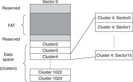
The simplified diagram illustrates a hypothetical example of a FAT file system formatted for 1,022 clusters, each composed of 16 sectors. (Notice that the data area always starts with cluster number 2.) In this example, each cluster would contain 8 KB of data and the total storage capacity would be about 8 MB.
Note that the larger clusters are, the fewer will be required to manage the entire memory space and the smaller the allocation table required, hence the higher efficiency of the file system. On the contrary, if many small files are to be written, the larger the cluster size, the more space will be wasted. It is typically the responsibility of the operating system, when formatting a storage device for use with a FAT file system, to decide the ideal cluster size to be used for an optimal balance.
The File Allocation Table
In a FAT16 file system, the File Allocation Table is essentially an array of 16-bit integers. Each element of the table represents one cluster. If a cluster is considered empty and available, the corresponding entry in the table will contain the value 0x0000. If a cluster is in use and it contains an entire file of data, its corresponding entry in the table will contain the value 0xFFFF. If a file is larger than the size of a single cluster, a chain of clusters is formed. In the FAT each element will contain the index of the next cluster in the chain. The last cluster in the chain will have the corresponding entry set to 0xFFFF.
Additionally, certain unique values are used to mark reserved clusters (0x0001) and bad clusters (0xFFF7). Since 0x0000 and 0x0001 have been assigned special meanings (free and reserved, respectively), this explains why the convention wants the cluster counting to start in the data area with cluster number 2. Inside the FAT, the corresponding first two entries are similarly reserved.
In Figure 15.2, you can see an example of a FAT for the system presented in our previous example in Figure 15.1. Clusters 0 and 1 are reserved. Cluster 2 appears to contain some data, meaning that some or all of the (16) sectors forming the cluster have been filled with data from a file whose size must have been less than 8 KB.
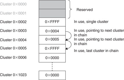
Cluster 3 appears to be the first cluster in a chain of three that also includes Clusters 4 and 5. All of Cluster 3 and 4 sectors and some or all of Cluster 5 sectors must have been filled with data from a file whose size (we can only assume so far) was more than 16 KB but less than 24KB. All following clusters appear to be empty and available.
Notice that the size of a FAT itself is dictated by the total number of clusters multiplied by 2 (2 bytes per cluster) and that it can spread over multiple sectors. In our previous example, a FAT of 1,024 clusters would have required 2,048 bytes, or four sectors of 512 bytes each. Also, since the file allocation table is perhaps the most critical structure in the entire FAT file system, multiple copies (typically two) are maintained and allocated one after the other before the beginning of the data space.
The Root Directory
The role of the FAT is to keep track of how and where data is allocated. It does not contain any information about the nature of the file to which the data belonged. For that purpose there is another structure, called the root directory, whose sole purpose is that of storing filenames, sizes, dates, times, and a number of other attributes. In a FAT16 file system, the root directory, or simply the root from now on, is allocated in a fixed amount of space and a fixed position right between the FAT (second copy) and the first data cluster (cluster #2), as shown in Figure 15.3.
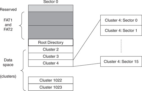
Since both position and size (number of sectors) are fixed, the maximum number of files (or directory entries) in the root directory is limited and determined when formatting the media. Each sector allocated to the root will allow for 16 file entries to be documented where each entry will require a block of 32 bytes, as represented in Figure 15.4.
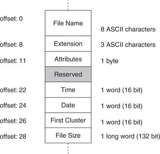
The Name and Extension fields are the most obvious if you are familiar with the older Microsoft operating systems using the 8:3 conventions. The two fields need only to be padded with spaces and the dot can be discarded.
The Attributes field is composed of a group of flags with the meanings shown in Table 15.1.
Table 15.1 File attributes in a directory entry.
| Bit | Mask | Description |
| 0 | 0×01 | Read only |
| 1 | 0×02 | Hidden |
| 2 | 0×04 | System |
| 3 | 0×08 | Volume label |
| 4 | 0×10 | Subdirectory |
| 5 | 0×20 | Archive |
The Time and Date fields refer to the last time the file was modified and must be encoded in a special format to compress all the information in just two 16-bit words (see Tables 15.2 and 15.3).
Table 15.2 Time encoding in a directory entry field.
| Bits | Description |
| 15–11 | Hours (0-23) |
| 10–5 | Minutes (0-59) |
| 4–0 | Seconds/2 (0-29) |
Table 15.3 Date encoding in a directory entry field.
| Bits | Description |
| 15–9 | Year(0 = 1980, 127 = 2107) |
| 8–5 | Month (1 = January, 12 = December) |
| 4–0 | Day (1-31) |
Notice how the Date field encoding does not allow for the code 0x0000 to be interpreted as a valid date. This can provide clues to the file system when the field is not used or could be corrupted.
The First Cluster field provides the fundamental link with the FAT table. This 16-bit word contains the number of the first, and possibly only, cluster containing the file data.
Finally, the Size field, a 32-bit integer, contains the size (in bytes) of the file data.
Looking at the first character of the filename in a directory entry, we can also tell if and how the entry is currently in use:
There is a third possibility when a file is removed from the directory. In this case the first character of the filename is simply replaced by a special code (0xE5). This indicates that the contents of the entry are no longer valid and the entry can be reused for a new file at the next opportunity. However, when browsing through the list searching for a file, we should continue because more active entries might follow it.
There would be much more to say to fully document the structure of a FAT16 file system, but if you have followed the introduction so far, you should have a reasonable understanding of its core mechanisms and you will be ready to dive in for more detail since we will start soon writing some code.
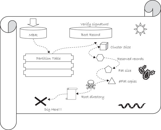
The Treasure Hunt
So far we have maintained a certain level of simplification by ignoring some fundamental questions, such as:
The answers to all those questions will be found soon, but the process will resemble a treasure hunt more than a logical sequence of steps. In fact, you will find the first set of clues in Figure 15.5. By interpreting these clues we will gradually build a new function that will allow us to mount the file system and unlock its contents—the treasure.
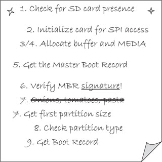
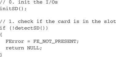
Using the SDMMC.c module functions developed in our previous explorations, we will start by initializing the I/Os with the initSD() function and checking for the presence of the card in the slot.
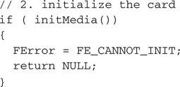
We will proceed by initializing the SD card for operation in SPI mode with the initMedia() function.
We will also use the standard C libraries malloc() function to dynamically allocate two data structures:
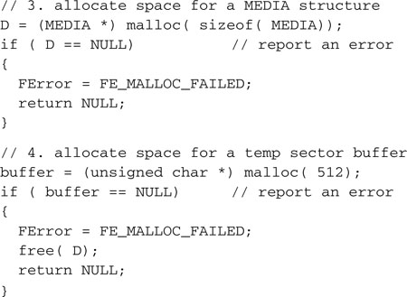
The first one is called MEDIA. It will be fully revealed to you later on but, for now, it will suffice to say that it will act as the repository for the many “answers” we are seeking. Perhaps a more appropriate name would’ve been CHEST?
The second structure, called buffer, is simply a 512-byte large array that will be used to retrieve sectors of data during the hunt.
Notice that to allow the malloc() function to successfully allocate memory, you must remember to inform the MPLAB® C32 linker to reserve some RAM space for the heap.
Hint
Follow the Project Build checklist to learn how to reach and modify the linker settings of your project.
Mostly historical reasons dictate that the first sector (LBA 0) of a mass storage device will contain what is commonly known as a master boot record (MBR).
Here is how we invoke the readSECTOR() function for the first time to access
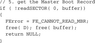
A signature, consisting of a specific word value (0x55AA) present in the last word of the MBR sector, will confirm that we have indeed read the correct data.
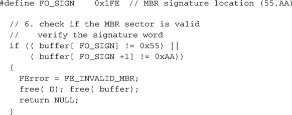
Once upon a time, this record used to contain actual code to be executed by a PC upon power-up. No personal computer does this anymore, though, and certainly there is no use for that 8086 code in our PIC32 applications. Most of the time you will find the MBR (see Figure 15.6) to be completely filled with zeros except for a few locations where critical information used to be stored. For example, starting at offset 0x01BE, you will find what is called a partition table. This table is composed of only four entries of 16 bytes each. The role of a partition table is that of allowing for a single media device to host multiple operating systems and/or split the storage space in safe areas, where each one acts as a completely separate device.
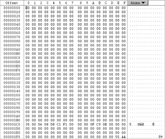
For our purposes it is safe to assume (demand) that the entire SD/MMC card is formatted with a single partition. Therefore, we need to focus only on the first entry (16-byte block) in the partition table. Of those 16 bytes, we need to access only a few to obtain:
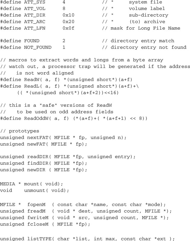
A couple of macros will help us read the data from the partition table and assemble it into 16-bit and 32-bit words:
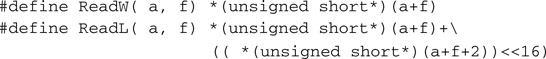
Also, the following definitions will point us to the right offset in the MBR.
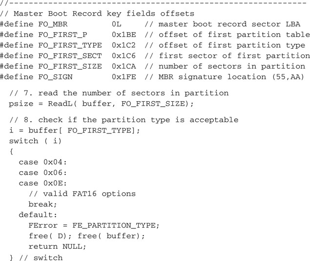
For historical reasons, several codes correspond to different types of partitions. We will be able to correctly decode at least three types of FAT16 partitions, including 0x04,0x06, and 0x0E.
Getting access to the MBR and finding the partition table is a bit like getting a map with a new set of symbols and clues that need to be interpreted (see Figure 15.7).
Extracting a 32-bit word found at offset FO_FIRST_SECT (0x1C6) as part of the first (and the only, in our assumptions) partition table entry, we obtain the address (LBA) of the very first sector of the partition.
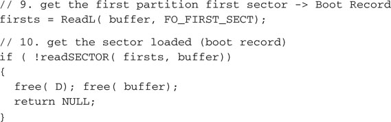
It has a signature, similarly to the MBR, located in the last word of the sector, and we need to verify it before proceeding.
It is called the (first partition) boot record, and once more it is supposed to contain actual executable code that is of no value to us (see Figure 15.8).
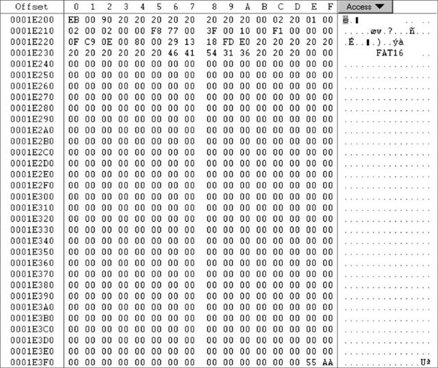
Fortunately, in the same record at fixed and known positions there are more of the answers we were looking for and new clues that will help us complete the map of the entire FAT16 file system. These are the key offsets in the boot record buffer:
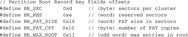
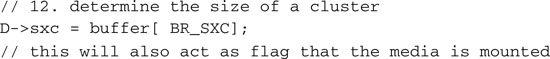
With the following code we can calculate the size of a cluster:
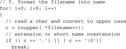
Determine the position of the FAT, its size, and the number of copies:
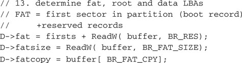
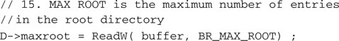
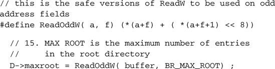
Find the position of the root directory, too:
![]()
But be careful now! As we get ready to make the last few steps, watch out for a trap!
Can you see it? No? Okay, here’s a hint: Look at the value of the BR_MAX_ROOT offset as defined a few lines before. You will notice that this is an odd address (0x11). This is all it takes for the ReadW() macro, which attempts to use it as a word address, to throw a processor exception (misaligned word access) and trap the PIC32 in the general exception handler!
We need a special macro (perhaps less efficient) that can assemble a word 1 byte at a time without falling into the trap!
The last two pieces of information are easy to grab now. With them we learn where the data area (divided into clusters) begins and how many clusters are available:
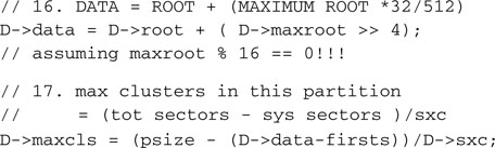
It took us as many as 17 careful steps to get to the treasure, but now we have all the information we need to fully figure out the layout of the FAT16 file system present on the SD/MMC memory card or, practically, any other mass storage media formatted according to the FAT16 standard. The treasure, after all, is nothing more than another map—a map we will use from now on to find files on a mass storage device (see Figure 15.9).
It’s time to organize the information we spent so much effort to retrieve. We will use the MEDIA structure, allocated on the heap at the very beginning.

All the code we have developed can now be assembled in the mount() function. This is a name that will sound familiar to those of you who have experience in programming for the Linux family of operating systems.
For a mass storage device to be used in Linux, it must be first “mounted” on the file system or, in other words, attached as a new branch of the main (system) file system. Windows users might not be familiar with the concept because they don’t have the option to choose if, when, or where a new device file system is mounted. All new mass storage devices are automatically and unconditionally “mounted” by Windows at power-up, or after insertion of any removable media, at the very root of the Windows file system by assigning them a unique, single-letter identifier (C:, D:, E:, and so on).
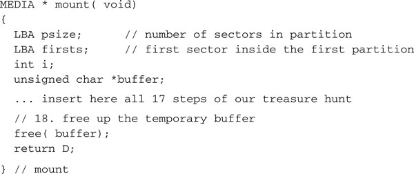
Let’s also define a global pointer D to a MEDIA structure. It will serve as the root for the entire file system in the assumption, for now, that only one storage device will be available at any given point in time (one connector/slot, one card).
![]()
We will also define an unmount() function that will have the sole duty of releasing the space allocated for the MEDIA structure.
Opening a File
Now that we have unlocked the secret of the FAT16 file system, we can return to our original objective: accessing individual files and sharing them with a PC. In this section we will develop a set of high-level functions similar to those used for file manipulation in most operating systems. We will need a function to find a file location on the storage device, one for reading the data sequentially from the file, and possibly one more to write data and create new files.
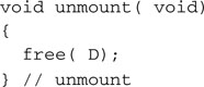
In a logical order we will start developing what we will call the fopenM() function. Its role will be that of finding all possible information regarding a file (if present) and gathering it in a new structure that we will call MFILE.
Note
The name of this structure was chosen so to avoid conflicts with similar structures and functions defined inside the standard C library stdio.h.
I know, at first sight it looks like a lot—it is more than 40 bytes large—but as you will see in the discussion, we will end up needing all of them. You will have to trust me for now.
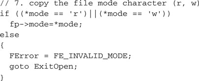
Mimicking standard C library implementations (common to many operating systems), the fopenM() function will receive two (ASCII) string parameters: the filename and a “mode” string, containing r or w, that will indicate whether the file is supposed to be opened for reading or writing.
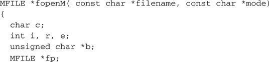
To optimize memory usage, an MFILE structure is allocated only when necessary, and it is in fact one of the first tasks of the fopenM() function. A pointer to the data structure is its return value. Should fopenM() fail, a NULL pointer will be returned.
Of course a prerequisite for opening a file is to have the storage device file system mapped out, and that is the responsibility of the mount() function. A pointer to a MEDIA structure must have already been deposited in the global D pointer.
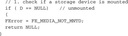
Since all activity with the storage device must be performed in blocks of 512 bytes, we will need that much space to be allocated for us to act as a read/write buffer.
Only if that amount of memory is available can we proceed and allocate some more memory for the MFILE structure proper.
The buffer pointer and the MEDIA pointers can now be recorded inside the MFILE data structure.
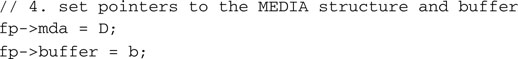
The filename parameter must be extracted and each character must be translated to uppercase (using the standard C library functions defined in ctype.h) and padded, if necessary, with spaces to an eight-character length.
Similarly, after discarding the dot, an extension of up to three characters must be formatted and padded.
Though most C libraries provide extensive support for multiple “modes” of access to files, such as distinguishing between text and binary files and offering an “append” option, we will accept, at least initially, a subset consisting of just the two basic options: r and w.
With the filename properly formatted, we can now start searching the root directory of the storage device for an entry of the same name.
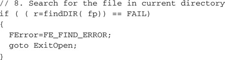
Let’s leave the details of the search out for now and trust the findDIR() function to return to us one of three possible values: FAIL, and eventually NOT_FOUND. A possible failure must always be taken into account. After all, before we consider the possibility of major fatal failures of the storage device, there is always the possibility that the user simply removed the card from its slot without our knowledge. If that is the case, as in all prior error cases, we have no business continuing in the process. We’d better immediately release the memory allocated thus far and return with a NULL pointer after leaving an error code in the dedicated “mail box” FError, just as we did during the mount process.
However, if the search for the file is completed without error (whether it was found or not), we can continue initializing the MFILE structure.
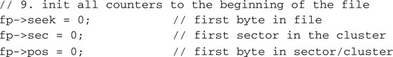
The counter seek will be used to keep track of our position inside the file as we sequentially access its contents. Its value will be a 32-bit integer (unsigned) between 0 and the size of the entire file expressed in bytes.
The sec field will keep track of which sector inside the current cluster we are currently operating on. Its value will be an integer between 0 and sxc-1, the number of sectors composing each data cluster. Finally, pos will keep track of which byte inside the current buffer we are going to access next. Its value will be an integer between 0 and 511.
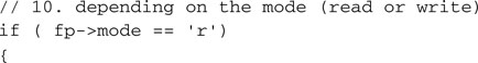
At this point, different things need to be done depending on whether an existing file needs to be opened for reading or a new file needs to be created for writing. Initially we will complete all the necessary steps for the fopenM() function when invoked in the read (r) mode, in which case the file had better be found.
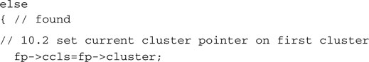
If it was indeed found, we trust the findDIR() function will have filled a couple more fields of the MFILE structure for us, including:
The first cluster number will become our current cluster: ccls.

Now we have all the information required to identify the first sector of data into the buffer. The function readDATA(), which we will describe in detail shortly, will perform the simple calculation required to convert the ccls and sec values into an absolute sector number inside the data area and will use the low-level readSECTOR() function to retrieve the data from the storage device.
Notice that the file length is not constrained to be a multiple of a sector size, so it is perfectly possible that only a part of the data retrieved in the buffer belongs to the actual file. The MFILE structure field top will help us keep track of where the actual file data ends and padding possibly begins.
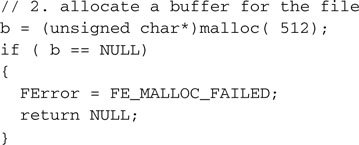
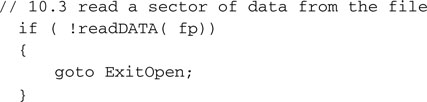
This is all we really need to complete the fopenM() function, so when opening a file for reading, we can return with the precious pointer to the MFILE structure.
![]()
In case any of the previous steps failed, we will exit the function returning a NULL pointer after having released both the memory allocated for the sector buffer and the MFIEL structure.
In a top-down fashion, we can now complete the two accessory functions used during the development of fopenM(), starting with readDATA():
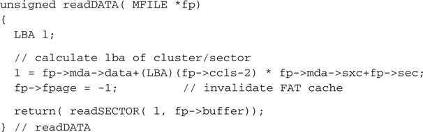
Ignoring for a moment the fpage field, notice how we use data and sxc from the MEDIA structure to compute the correct absolute address (LBA) of the desired data sector. Very simple!
Similarly, we create a function to read from the root directory a sector of data containing a given entry.
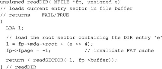
We know that each directory entry is 32 bytes large; therefore each sector will contain 16 entries.
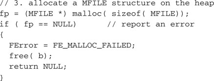
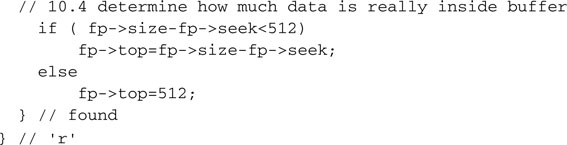
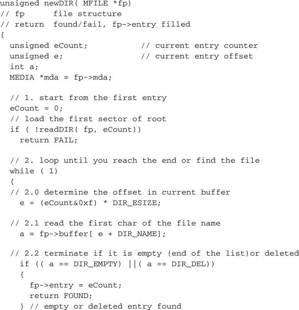
The findDIR() function can now be quickly coded as a short sequence of steps enclosed in a search loop through all the available entries in the root directory.
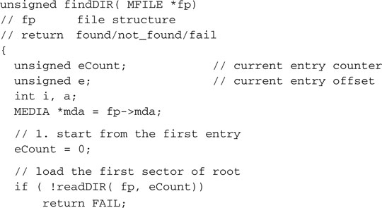
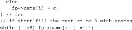
We start by loading the first root sector, containing the first 16 entries, in the buffer. For each entry we compute its offset inside the buffer.
And we inspect the first character of the entry filename.
![]()
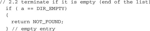
If its value is 0, indicating an empty entry and the end of the list, we can immediately exit, reporting that the filename was not found.
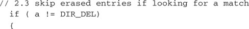
The other possibility is that the entry was marked as deleted, in which case we will skip it but we will continue searching.
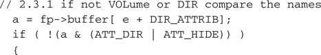
Otherwise, it’s a valid and healthy entry, and we should check the attributes to determine if it corresponds to a proper file or any other type of object. The possibilities include:
None of them is of our concern, since we will choose to keep things simple and we will steer clear of the most advanced and sometimes patented features of the more recent versions of the FAT file system standard.
We will then compare the filenames character by character, looking for a complete match.
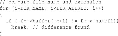
Only if every character matches will we extract the essential pieces of information from the entry and copy them into the MFILE structure, returning a FOUND code.
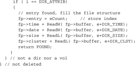
Should the filename and extension differ, we will simply continue our search with the next entry, remembering to load the next sector from the root directory after each group of 16 entries.
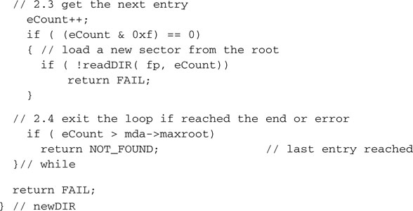
We know the maximum number of entries in the root directory (maxroot) and we need to terminate our search if we reach the end of the directory without a match indicating NOT_FOUND.
Reading Data from a File
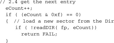
Finally, this is the moment we have been waiting for so long. The file system is mounted, a file is found and opened for reading. It is time to develop the freadM() function to freely read blocks of data from it.
The name, number, and sequence of parameters passed to this function are again supposed to mimic closely that of similarly named functions available in the standard C libraries. A destination buffer is supplied where the data read from the file will be copied, and a number of bytes is requested while passing the usual pointer to an open MFILE structure.
The freadM() function will do its best to read as many of the bytes requested as possible from the file and will return an unsigned integer value to report how many it effectively managed to get. In our simple implementation, if the number returned will not be identical to that requested by the calling application, we will have to assume that something major has happened. Most probably the end of file has been reached, but we will not make a distinction if, instead, another type of failure has occurred—for example, the card has been removed during the process.
As usual, we will not trust the pointer passed in the argument, and we will check instead to see whether it is pointing to a valid, initialized, MFILE structure.
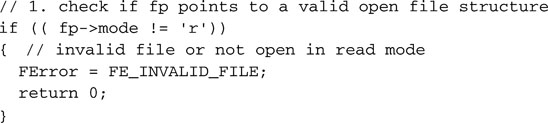
Only then we will enter a loop to start transferring the data from the sector data buffer.
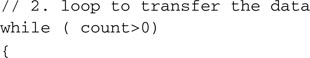
Inside the loop, the first condition to check will be our current position with regard to the total file size.
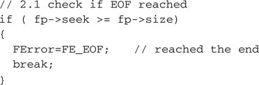
Notice that this error will be generated only if the application calling the freadM() function will ignore the previous symptom: the last freadM() call returned with a number of data bytes inferior to what was requested or if the calling application has requested the exact number of bytes available in the file with the previous calls.
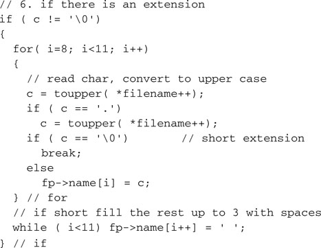
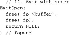
Otherwise we will verify whether the current buffer of data has already been used up completely.
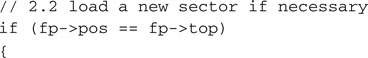
If necessary we will reset our buffer pointers and attempt to load the next sector from the file.
![]()
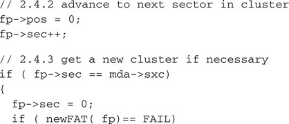
If we already used up all the sectors in the current cluster, this might force us to step into the next cluster by peeking inside the FAT and following the chain of clusters.
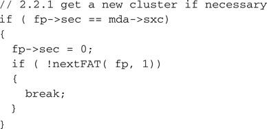
In either case we load the new sector of data in the buffer, paying attention to verify the possibility that it might be the last one of the file and it might be only partially filled.
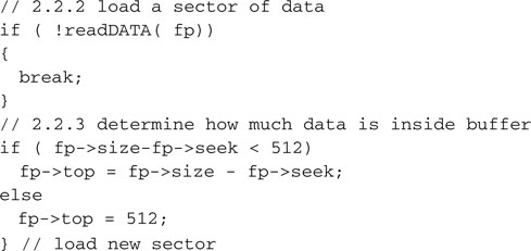
Now that we know we have data in the buffer, ready to be transferred, we can determine how much of it we can transfer in a single chunk.

Using the memcpy() function from the standard C libraries (string.h) to move a block of data from the file buffer to the destination buffer, we get the best performance as these routines are optimized for speed of execution. The pointers and counters can be updated and the loop can be repeated until all the data requested has been transferred.
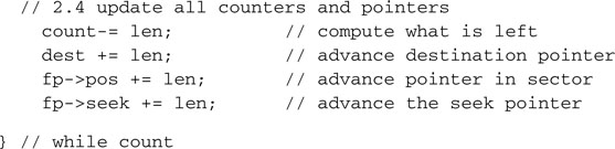
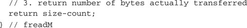
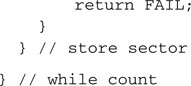
Finally, we can exit the function and return the number of actual bytes transferred in the loop.
The nextFAT() function helped us follow the cluster chain, hopping from the current cluster to the next one.
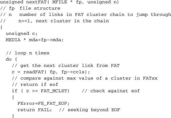
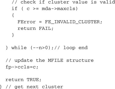
As you noticed, the nextFAT() function uses, in its turn, the services of the readFAT() function to perform the hard work of actually loading an entire segment (sector) of the FAT.
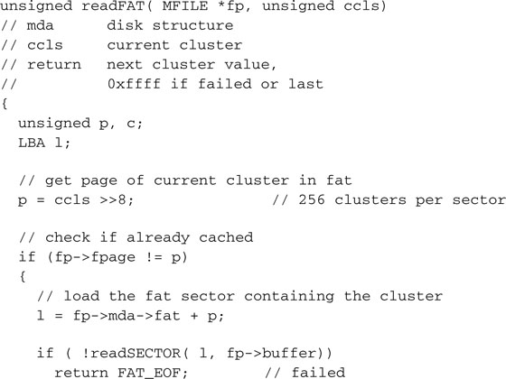
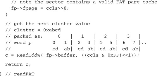
Since each sector of the FAT (we will call it a page from now on) contains 256 entries, it is very likely that when we follow a chain of clusters or, as soon will be the case when we look for an empty cluster, we will need to access the same page over and over. Instead of wasting time continuously reloading the same sector, the readFAT() function tries to keep track of the contents (cache) of the file buffer using the fpage element of the MFILE structure to maintain the index of the last FAT page loaded. This requires some cooperation from the readDATA() and readDIR() functions so that when they overwrite the buffer contents with their contents (file data and directory table entries, respectively), they update the fpage index, invalidating it, using the index value –1 to alert readFAT().
Closing a File
Since we can only open a file for reading with the fopenM() function as defined so far, there is not much work to perform upon closing the file.
The Fileio Module
We can save all the functions created so far in a file called fileio.c, the beginning of our file input/output library. We will need to add the usual header and a few include files:
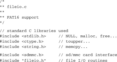
And of course, we will need to create a fileio.h include file as well, with all the definitions and prototypes that we want to publish for future applications to use.
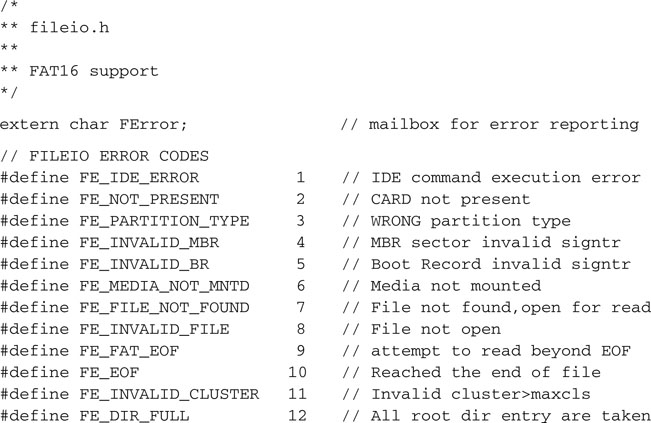
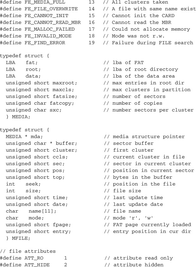
Don’t worry for now if we have not fleshed out all the functions yet; we will continue working on them as we proceed through the rest of this chapter.
Testing fopenM() and freadM()
It might seem like a long time since we built the last project. To verify the code that we have developed so far, we had to reach a critical mass, a minimal core of routines without which no application could have worked. Now that we have this core functionality, we can develop for the first time a small test program to read from an SD/MMC card a file created in the FAT16 file system. We will call it ReadTest.
The idea is to copy a text file (any text file would work) on the SD/MMC card from your PC and then have the PIC32 read the file, count the number of lines, and display it on the LCD.
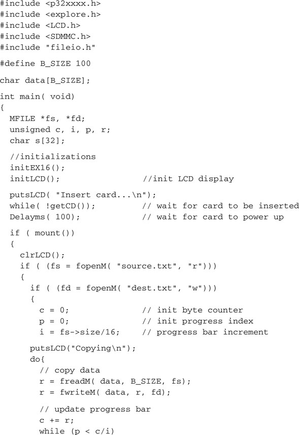
Here is the main module that you will save as ReadTest.c:
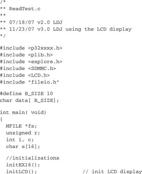
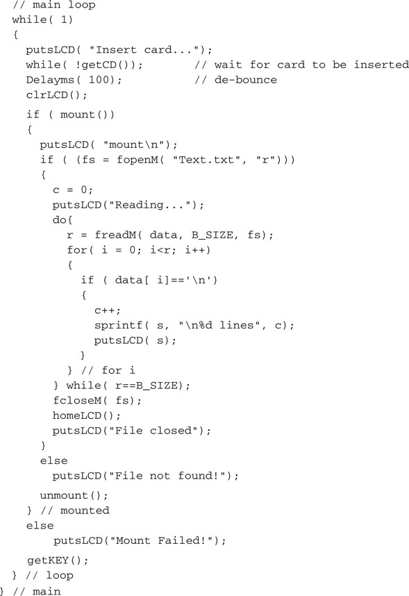
The sequence of operation is similar to the one we adopted when testing the basic SD/MMC access module, only this time instead of calling the initMedia() function and then starting to directly read and write sectors to and from the SD/MMC card, we called the mount() function to access the FAT16 file system on the card. We opened the data file using its “proper” name, and we read data from it in blocks of arbitrary length (B_SIZE), scanning them for new line characters to mark the end of each text line. Once we’d exhausted the content of the entire file, we closed it, deallocating all the memory used.
To build the project, you will need to remember to include all the following modules:
Remember to follow the checklist for your in-circuit debugger of choice, but also in the Project Build Options dialog box (Project | Build Options | Project), remember to reserve some space for the heap so that the fileio functions will be able to allocate memory dynamically for the file system structures and buffers. Even if 580 bytes should suffice, give the heap ample room to maneuver; I recommend you allocate at least 2 K bytes.
After building the project and programming the Explorer 16 board, we are ready to run the test. If all goes well you will be prompted to insert the SD card in the slot and you will quickly see a counter updating on the second line of the LCD, probably too fast for you to read anything but the last value.
Notice that you can recompile the project and run the test with different sizes for the data buffer from 1 byte to as large as the memory of the PIC32 will allow. The freadM() function will take care of reading as many sectors of data required to fulfill your request as long as there is data in the file.
Writing Data to a File
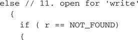
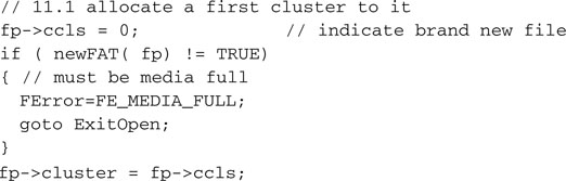
We are far from finished, though. The fileio.c module is not complete until we include the ability to create new files. This will require us to create an fwriteM() function but also to complete a piece of the fopenM() function and a considerable extension of the fcloseM() function. So far we had fopenM() return with an error code when a file could not be found in the root directory or the mode was not r. But this is exactly what we want when we open a new file for writing. When we check for the mode parameter value, we need to add a new option. This time, it is when the file is NOT_FOUND during the first scan of the directory that we want to proceed.
A new file needs a new cluster to be allocated to contain its data. The function newFAT() will be used to search in the FAT for an available spot, a cluster that is still marked (with 0x0000 ) as available. This search could fail and the function could return an error that, among other things, could indicate that the storage device is full and all data clusters are taken. Should the search be successful, though, we will take note of the new cluster position and update the MFILE structure, making it the first cluster of our new file.
Next, we need to find an available entry space in the directory for the new file. This will require a second pass through the root directory, this time looking for either the first entry that is marked as deleted (code 0xE5 ) or for the end of the list where an empty entry is found (marked with the code 0x00 ).
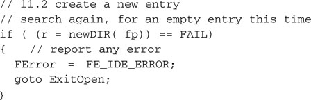
The function newDIR() will take care of finding an available entry and, similarly to the findDIR() function used before, will return one of three possible codes:
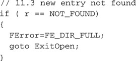
In both the first two cases we have to report an error and we cannot continue. But if an entry is found, we have plenty of work to do to initialize it.
After calculating the offset of the entry in the current buffer, we will start filling some of its fields with data from the MFILE structure. The file size will be first.
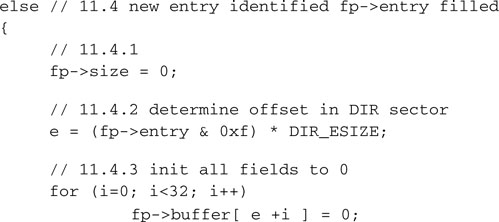
The time and date fields could be derived from the RTCC module registers or any other timekeeping mechanism available to the application, but a default value will be supplied here only for demonstration purposes.
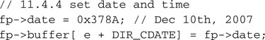
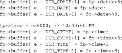
The file’s first cluster number, the filename, and the attributes (defaults) will complete the directory entry.
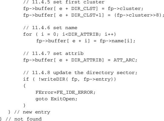
Back to the results of our first search through the root directory. In case a file with the same name was indeed found, we will need to report an error.
Alternatively, we would have had to delete the current entry first, release all the clusters used, and then start from the beginning. After all, reporting the problem as an error is an easier way out for now.
So much for the changes required to the fopenM() function. We can now start writing the proper new fwriteM() function, once more modeled after a similarly named standard C library function.
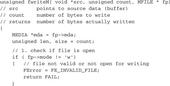
The parameters passed to the function are identical to those used in the freadM() function. The first test we will perform on the integrity of the MFILE structure, passed as a parameter, is the same as well. It will help us determine if we can trust the contents of the MFILE structure having been successfully prepared for us by a call to fopenM().
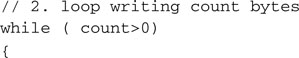
The core of the function will be a loop as well:
Our intention is that of transferring as many bytes of data as possible at a time, using the fast memcpy() function from the string.h libraries.

We need to update a number of pointers and counters to keep track of our position as we add data to the buffer and increase the size of the file.
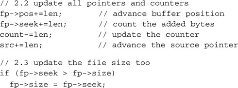
Once the buffer is full, we need to transfer the data to the media in a sector of the currently allocated cluster:
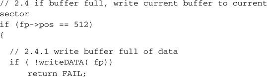
Notice that an error at this point would be rather fatal. We will return the code FAIL, the value of which is 0, therefore indicating that not a single byte has been transferred. In fact, all the data written to the storage device thus far is now lost.
If all proceeds correctly, though, we can now increment the sector pointers, and if we have exhausted all the sectors in the current cluster, we must consider the need to allocate a new one, calling newFAT() once more.
Shortly, when developing newFAT(), we will have to make sure that the function accurately maintains the chaining of the clusters in the FAT as they get added to a file.
The function is now complete and we can report the number of bytes written upon exit from the loop.
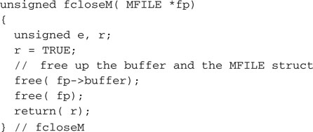
Closing a File, Take Two
Closing a file opened for reading was a mere formality and a matter of releasing some memory from the heap, but when we close a file that has been opened for writing, there is an additional amount of housekeeping work that needs to be performed.
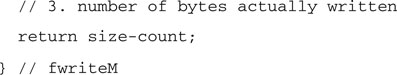
A new and improved fcloseM() function is needed, and it will start with a check of the mode field.
In fact, when we close a file, there might still be some data in the buffer that needs to be written to the storage device, although it does not fill an entire sector.
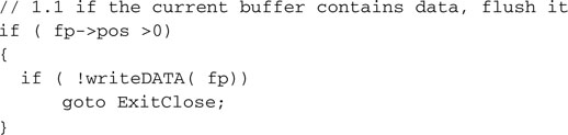
Once more, any error at this point is a rather fatal event and will mean that all the file data is lost, since the fcloseM() function will not properly complete.
The proper root directory sector must be retrieved and an offset for the directory entry must be calculated inside the buffer.
Next we need to update the file entry in the root directory with the actual file size (it was initially set to zero).

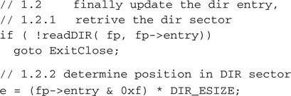
Finally, the entire root directory sector containing the entry is written back to the media.
If all went well, we will complete the fcloseM() function, deallocating the memory used.
Accessory Functions
In completing fopenM(), fcloseM() and creating the new fwriteM() function, we have used a number of lower-level functions to perform important repetitive tasks.
We will start with newDIR(), used to find an available spot in the root directory to create a new file. The similarity with findDIR() is obvious, yet the task performed is very different.
The function newFAT() was used to find an available cluster to allocate for a new block of data/new file:
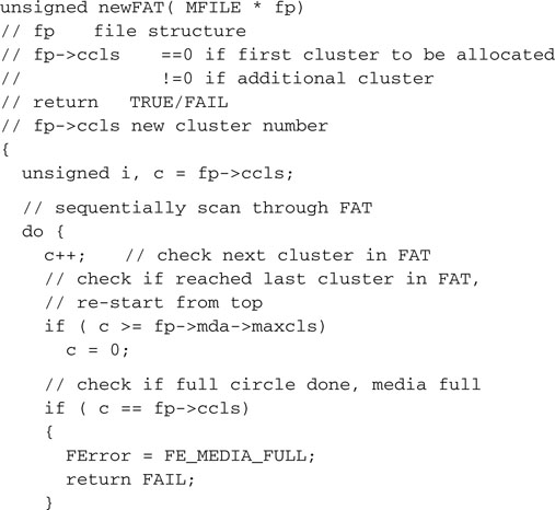
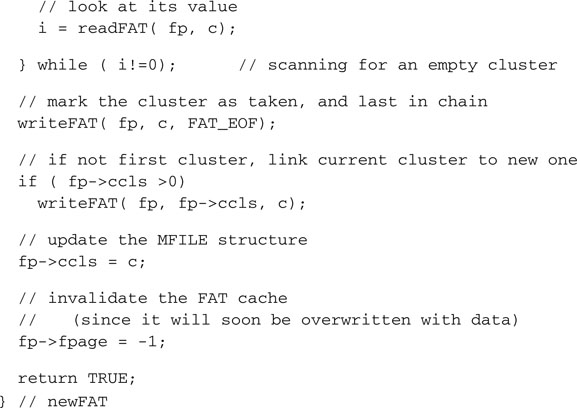
When allocating a new cluster beyond the first one, newFAT() keeps linking the clusters in a chain, and it marks every cluster as properly used. In its turn, the function uses one more accessory function. The writeFAT() function updates the contents of the FAT and keeps all its copies current.
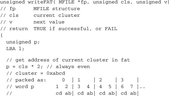
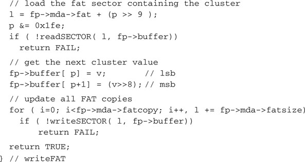
Finally, writeDATA() was used by both fwriteM() and fcloseM() to write actual sectors of data to the storage device, computing the sector address based on the current cluster number.
Testing the Complete Fileio Module
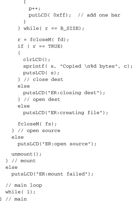
It is time to test the functionality of the entire fileio.c module we just completed. This time, after mounting the file system, we will open a source file (which could be any file) and copy its contents into a new “destination” file that we will create on the spot. Here is the code we will use for the WriteTest.c main file.
Make sure you replace the source filename (SOURCE.TXT) with the actual name of the file you copied on the card for the experiment.
After creating a new project (let’s call it WriteTest this time), we will need to add all the necessary modules to the project window, including:
Once more, remember to follow the checklists for a new project and for the in-circuit debugger setup, but this time remember to add even more space for the heap so that we will be able to dynamically allocate two buffers for two MFILE structures.
Note
Once enough space is left for the global variables and the stack, there is no reason to withhold any memory from the heap. Allocate as large a heap as possible to allow malloc() and free() to make optimal use of all the memory available.
After building the project and programming the executable on the Explorer 16 board, we are ready to run the test. Insert the SD card in the slot when prompted, and if all goes well for a fraction of a second, dependent on the size of the source file chosen, you will be able to see a progress bar gradually filling the second line of the LCD. When the copy is completed, a message similar to the following will appear on the LCD:
![]()
Once more the actual number of bytes should reflect the size of the source file used. At this point if you transfer the SD/MMC card back to your PC, you should be able to verify that a new file has been created (see Figure 15.10).
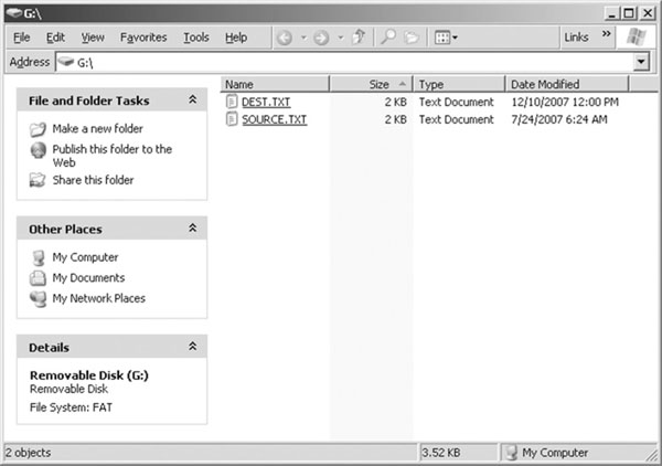
Its size and contents are identical to the source file, whereas the date and time reflect the values we set in the fopenM() function.
Notice that if you try to run the test program a second time, it is bound to fail now.
![]()
This is because, as discussed during the development of the fopenM() function, we chose to report an error when trying to create a new file (open a file for writing) and we find a file with the same name already present.
Notice that you can recompile the project and run the test with different sizes for the data buffer, from 1 byte to as large as the memory of the PIC32 will allow. Both the freadM() and fwriteM() functions will take care of reading and writing as many sectors of data as are required to fulfill your request. The time required to complete the operation will change slightly, though.
Code Size
The size of the code produced by the WriteTest project is considerably larger than the simple SDMMC.c module we tested in the previous chapter (see Figure 15.11).
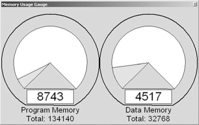
Still, with all optimization options turned off, the code will add up to just 8,743 words. This represents only 6 percent of the total program memory space available on the PIC32MX360. I consider this a very small price to pay for a lot of functionality!
Debriefing
In this lesson we learned the basics of the FAT16 file system and developed a small interface module that allows a PIC32 microcontroller to read and write data files to and from a generic mass storage device. By using the SDMMC.c module, developed in the previous lesson for the low-level interface, we have created a basic file I/O interface for SD/MMC memory cards.
Now you can share data between a PIC32 application and almost any other computer system that is capable of accessing SD/MMC cards, from PDAs to laptops and desktop PCs; from DOS, Windows, and Linux machines to Apple computers running OS-X.
Tips & Tricks
A frequent question I am asked by embedded-control engineers is: “How can I interface to a ’thumb drive’ (sometimes referred to as a USB stick), a USB mass storage device, to share/transport data between my application and a PC?”
The short answer is simple: “Don’t, if you can help it!” The longer answer is: “Use an SD card instead!” and here is why. As you have seen in this lesson and the previous one, reading and writing to an SD card (miniSD and microSD included) is really simple and requires very little code and only one SPI port.
The USB interface, on the other side, has all the appeal and appearance of simplicity from the user perspective, but reading and writing to a USB thumb drive can be deceptively complex and expensive for a modest embedded-control application. First, the simplicity of the SPI interface must be replaced by the relatively greater complexity of the USB bus interface. What is required, then, is not just the standard USB interface but a host USB interface and corresponding software stack.
As of this writing, it has already been announced that future versions of the PIC32 will offer an integrated host USB interface, but there will be a considerable price to pay in terms of Flash and RAM required to support the complete software stack. This can be estimated at several orders of magnitude larger and more complex than the basic SD/MMC card solution we examined today.
Exercises
Books
Pate, Steve D., Unix Filesystems: Evolution, Design, and Implementation (John Wiley, 2003 ). Windows is our primary concern when we think of sharing files with a personal computer, but you have to look at Unix (and Linux) to find serious file systems for mission-critical data storage.
Links
www.tldp.org/LDP/tlk/tlk-title.html. The Linux Kernel, by David A Rusling, is an online book that describes the inner workings of Linux and its file system.
http://en.wikipedia.org/wiki/File_Allocation_Table. Once more, this is an excellent page of Wikipedia that describes the history and many ramifications of the FAT technology.
http://en.wikipedia.org/wiki/List_of_file_systems. An attempt to list and classify all major computer file systems in use.
http://en.wikipedia.org/wiki/ISO-9660. Want to know how files are written on a CD-ROM? The ISO-9660 file system is the answer.