
Day 3 Message in a Bottle
The Plan
Yesterday we learned that there is a loop at the core of every embedded-control application, and we learned to code it in C using the while statement. Today we will continue exploring a variety of other techniques available to the C programmer to perform loops. Along the way, we will take the opportunity to briefly review integer variable declarations and increment and decrement operators, quickly touching on array declarations and usage. By the end of the day you will be ready for a hopefully entertaining project that will make use of all the knowledge you acquired during the day by creating a survival tool you’ll find essential should you ever be stranded on a deserted island.
Preparation
In this lesson we will continue to use the MPLAB© SIM software simulator, but once more an Explorer 16 demonstration board could add to the entertainment. In preparation for the new demonstration project, you can use the New Project Setup checklist to create a new project called Message and a new source file called Message.c.
The Exploration
In a while loop, a block of code enclosed by two curly brackets is executed if, and for as long as, a logic expression returns a Boolean true value (not zero). The logic expression is evaluated before the loop, which means that if the expression returns false right from the beginning, the code inside the loop might never be executed.
Do Loops
If you need a type of loop that gets executed at least once but only subsequent repetitions are dependent on a logic expression, you have to look at a different type of loop.
Let me introduce you to do loop syntax:
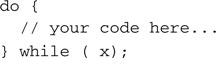
Don’t be confused by the fact that the do loop syntax is using the while keyword again to close the loop; the behavior of the two is very different.
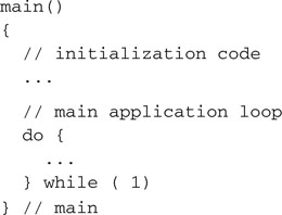
In a do loop, the code found between the curly brackets is always executed first; only then is the logic expression evaluated. Of course, if all we want to get is an infinite loop for our main() function, it makes no difference if we choose the do or the while:
Looking for curious cases, we might analyze the behavior of the following loop:
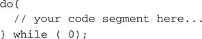
You will realize that the code segment inside the loop is going to be executed once and, no matter what, only once. In other words, the loop syntax around the code is, in this case, a total waste of your typing efforts and another good candidate for the “most useless piece of code in the world” contest.
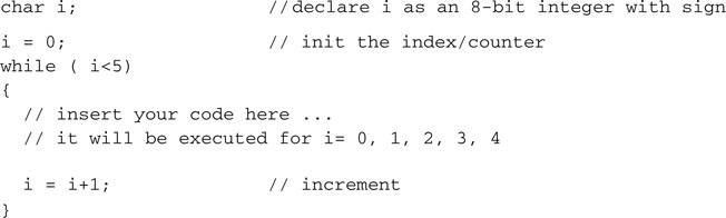
Let’s now look at a more useful example, where we use a while loop to repeatedly execute a piece of code for a predefined and exact number of times. First, we need a variable to perform the count. In other words, we need to allocate one or more RAM memory locations to store a counter value.
Note
In the previous two lessons we have been able to skip, almost entirely, the subject of variable declarations because we relied exclusively on the use of what are in fact predefined variables: the special-function registers of the PIC32.
Variable Declarations
We can declare an integer variable with the following syntax:
![]()
Since we used the keyword int to declare i as a 32-bit (signed) integer, the MPLAB C32 compiler will make arrangements for 4 bytes of memory to be used. Later, the linker will determine where those 4 bytes will be allocated in the physical RAM memory of the selected PIC32 model. As defined, the variable i will allow us to count from a negative minimum value –2,147,483,648 to a maximum positive value of +2,147,483,647. This is quite a large range of values—so large that most 8- and 16-bit compilers would have been so generous only for the next type up in the hierarchy of integer types, known as long, as in:
![]()
But this is one of the advantages of using a 32-bit microcontroller. The arithmetic and logic unit (ALU) of the PIC32 is actually performing all arithmetic operations with equal ease (same number of clock cycles) for 32-bit integers just as it would for a 16-bit or an 8-bit integer. The MPLAB C32 compiler therefore defaults immediately to 32-bit for the basic integer type (int) and makes long just a synonym for it.
This is all nice and dandy from a performance point of view, but it comes with a price in terms of memory space. The RAM memory space allocated to hold each integer variable in your program is now double what it used to be on an 8 or 16-bit PIC© microcontroller. Though it is true that we have more of it on the PIC32 models, RAM often remains one of the most precious resources in an embedded-control application.
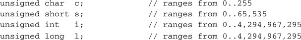
So if you don’t have a use for the huge range of values that the PIC32’s int and long types can offer and you are looking for a smaller counter, and you can accept a range of values from, say, –128 to +127, you can use the char integer type instead:
![]()
The MPLAB C32 compiler will use only 8 bits (a single byte) to hold c.
If a range of values from –32768 and +32767 is more what you were looking for, the short integer type is the right type for you:
![]()
The MPLAB C32 compiler will use only 16 bits (two bytes) to hold s. All four types can further be modified by the unsigned attribute, as in:
Now, if you really need a large range of values, nothing beats the long long type and its unsigned variant:
![]()
Note
The MPLAB C32 compiler will allocate 64 bits (8 bytes or RAM) for each long long variable, which can seem like a lot, but the workload you can expect from the PIC32 to crunch these numbers is not going to be much different than what it used to be for a PIC16 to work on a simple 16-bit integer.
There are then variable types defined for use in floating-point arithmetic:
![]()
But for our looping purposes, let’s stick with integers for now.
for Loops
Returning to our counter example, all we need is a simple integer variable to be used as index/counter, capable of covering the range from 0 to 5. Therefore, a char integer type will do:
Whether counting up or down, this is something you are going to do a lot in your everyday programming life. In C language, there is a third type of loop that has been designed specifically to make coding this common case easy. It is called the for loop, and this is how you would have used it in the previous example:
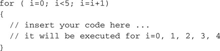
You will agree that the for loop syntax is compact, and it is certainly easier to write. It is also easier to read and debug later. The three expressions separated by semicolons and enclosed in the brackets following the for keyword are exactly the same three expressions we used in the prior example:
You can think of the for loop as an abbreviated syntax of the while loop. In fact, the logic expression is evaluated first and, if it’s false from the beginning, the code inside the loop’s curly brackets may never be executed.
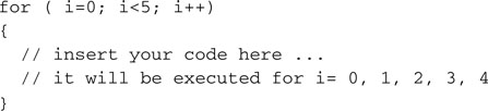
Perhaps this is also a good time to review another convenient shortcut available in C. There is a special notation reserved for the increment and decrement operations that uses the operators:

There will be much more to say on the subject in later chapters, but this will suffice for now.
More Loop Examples
Let’s see some more examples of the use of the for loop and the increment/decrement operators. First, a count from 0 to 4:
Then a count down from 4 to 0:

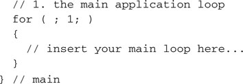
Can we use the for loop to code an (infinite) main program loop? Sure we can! Here is an example:
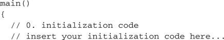
If you like it, feel free to use this form. As for me, from now on I will stick to the while syntax (it is just an old habit).
Arrays
Before starting to code our next project, we need to review one last C language feature: array variable types. An array is just a contiguous block of memory containing a given number of identical elements of the same type. Once the array is defined, each element can be accessed via the array name and an index. Declaring an array is as simple as declaring a single variable—just add the desired number of elements in square brackets after the variable name:

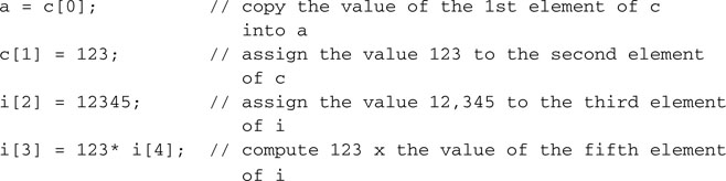
The same squared-brackets notation is used to refer to the content or assign a value to each element of an array, as in:
Note
In C language, the first element of an array has index 0, whereas the last element has index N-1, where N is the declared array size.
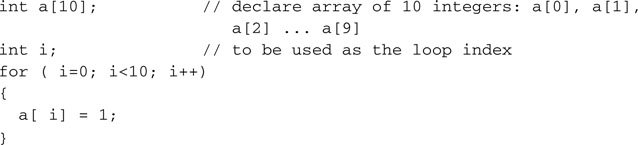
It is when we manipulate arrays that the for type of loop comes in very handy. Let’s see an example where we declare an array of 10 integers and we initialize each element of the array to a constant value of 1:
Sending a Message
It’s time to take all the new elements of the C language we have reviewed so far and put them to use in our next project. We will try once more to communicate with the outside world, this time using an entire row of LEDs connected to PortA, as they happen to be connected on the Explorer 16 demo board, flashing in a rapid sequence so that when we move the board left and right rhythmically they will display a short text message.
How about “Hello World!” or perhaps more modestly “HELLO”? Here is the code:
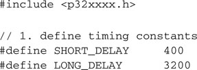
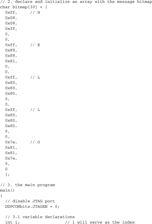
In section 1, we define a couple of timing constants so that we can control the flashing sequence speed for execution and debugging.
In section 2, we declare and initialize an 8-bit integer array of 30 elements, each containing an LED configuration in the sequence.
Hint
Convert the hex values in the array initialization to binary on a piece of paper and, using a highlighter or a red pen, mark each 1 on the page to see the message emerge.
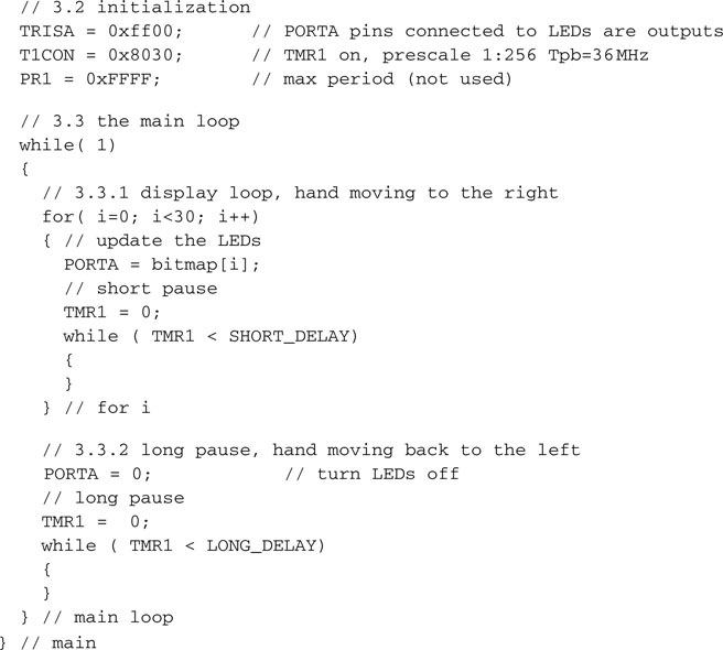
Section 3 contains the main program, with the variable declarations (3.1) at the top, followed by the microcontroller initialization (3.2) and eventually the main loop (3.3).
The main (while) loop, in turn, is further divided in two sections: Section 3.3.1 contains the actual LED Flash sequence, composed of 30 steps, to be played when the board is swept from left to right. A for loop is used for accessing each element of the array, in order. A while loop is used to wait on Timer1 for the proper sequence timing. Section 3.3.2 contains a pause for the sweep back, implemented using a while loop with a longer delay on Timer1.
Testing with the Logic Analyzer
To test the program, we will initially use the MPLAB SIM software simulator and the Logic Analyzer window:
The MPLAB SIM Setup and Logic Analyzer Setup checklists will help you make sure that you don’t forget any detail.
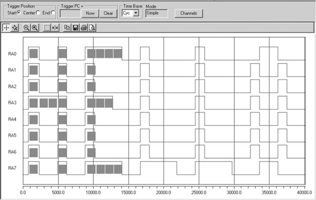
To help you visualize the output, I added a few red dots to represent the LEDs being turned on during the first few steps of the sequence. If you squeeze your eyes a bit and imagine you see an LED on wherever the corresponding pin is at the logic high level, you will be able to read the message.
Testing with the Explorer 16 Demonstration Board
If you have an actual Explorer 16 demonstration board and an MPLAB REAL ICE programmer and debugger available, the fun can be doubled:
After dimming the light a bit in the room, you should be able to see the message flashing as you “shake” the board. The experience is going to be far from perfect, though. With the Simulator and the Logic Analyzer window, we can choose which part of the sequence we want to visualize with precision and “freeze” it on the screen. On the demonstration board, you might find it quite challenging to synchronize the board’s movement with the LED sequence.
Consider adjusting the timing constants to your optimal speed. After some experimentation, I found that the values 400 and 3200, respectively, for the short and long delays were ideal, but your preferences might differ.
Testing with the PIC32 Starter Kit
If you have a PIC32 Starter Kit, it will be harder but not impossible to adapt our example to use only the three available LEDs connected to the PortD pins RD0, RD1, and RD2. Unfortunately, even if you get hold of a PIM adapter board to attach the Starter Kit to an Explorer 16 board, you won’t be able to see the demo in its full glory, because the Starter Kit uses the JTAG port, and that means that four out of the eight LEDs on PortA are not available.
This is not fair. In fact, I believe we need to change our strategy and find another way to send our message out to the world with the PIC32 Starter Kit. The idea is to use the old and trusty Morse code! Here is the sequence of light flashes required:
![]()
The rules are simple: Once chosen a basic pulse length for the dot (a couple tenths of a second), every other interval is required to generate a proper Morse code message based on integer multiples of it. A dash will be three times longer. The pause between dash and dots is going to be one single dot long, the pause between letters will be three dots long, and finally the pause between words will be five dots long. Once more, we can encode the entire message using an array of alternating 1s and 0s. Here is the modified code example:
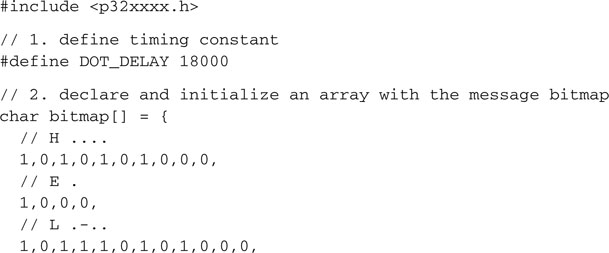
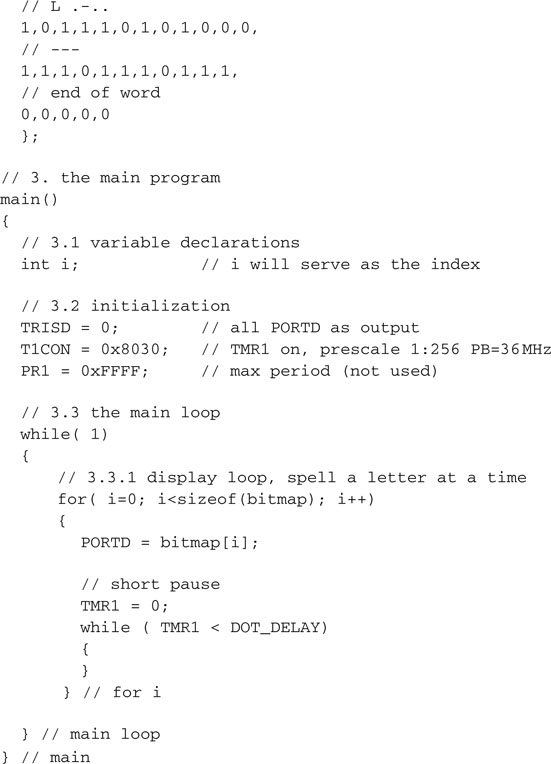
Notice that, to avoid having to count the dots and dashes manually to allocate the right amount of space for the bitmap array, I used a little trick. By leaving the square brackets ( [] ) empty in the declaration of the array, I essentially told the compiler to figure out by itself the right size based on the number of integers used in the follow list (between curly brackets {} ). Of course, this would have not worked if there had been no initialization list immediately following the array declaration. A problem would have occurred later in the for loop if I had no other way to know how many elements had eventually been added to the array. Luckily, the sizeof() function came to my rescue, giving me a byte count (the size of the array in bytes), and since each array element is a char type integer, that coincides with the exact number of elements I was looking for.
Debriefing
In this lesson we reviewed the declaration of a few basic variable types, including integers and floating points of different sizes. Array declarations and their initialization were also used to create an original “shaking” LED display first and Morse code later, using for loops to send messages to the world.
Notes for the Assembly Experts
The ++ and –– operators are actually much smarter than you might think. If the variable they are applied to is an integer, as in our trivial examples, there is little they can do to help, apart from saving you a few keystrokes. But if they are applied to a pointer (which is a variable type that contains a memory address), they actually increase the address by the exact number of bytes required to represent the quantity pointed to. For example, a pointer to 16-bit integers will increment its address by two, while a pointer to a 32-bit integer will increment its address by four, and so on.
The increment and decrement operators can also be applied inside a generic expression to operate before or after a variable content is fetched. Here are a few examples (assuming the initial conditions a=0 and b=1):
![]()
In this first case, a is assigned the value of b first, and b is incremented later.
![]()
In this second case, b is incremented first and then its (new) value is passed to a.
Use these interesting options with moderation, though. The actual convenience (as in reduction of keystrokes) is counterbalanced by an increased obfuscation of the code.
As per a potential increase in the efficiency, it is most probably negligible. In fact, whether you use the increment/decrement operators or not, the MPLAB C32 compiler optimizer, even at the lowest settings, can probably do a better job of optimizing the use of the PIC32 registers in a generic expression without you having to fiddle with these details.
Let me add one last word on loops. It can be confusing to see so many options: Should you test the condition at the beginning or the end? Should you use the for type or not? The fact is, in some situations the algorithm you are coding will dictate which one to use, but in many situations you will have a degree of freedom, and more than one type might do. Choose the one that makes your code more readable, and if it really doesn’t matter, as in the main loop, just choose the one you like and be consistent.
Notes for the PIC Microcontroller Experts
Depending on the target microcontroller architecture and ultimately the arithmetic and logic unit (ALU), operating on bytes versus operating on word quantities can make a big difference in terms of code compactness and efficiency. In the PIC16 and PIC18 8-bit architectures there is a strong incentive to use byte-sized integers wherever possible; in the PIC32, 32-bit word-sized integers can be manipulated with the same efficiency. The only limiting factor, preventing us from always using 32-bit integers with the MPLAB C32 compiler, is the consideration of the relative preciousness of the internal resources of the microcontroller, and in this case the RAM memory.
Notes for the C Experts
Even if PIC32 microcontrollers have a relatively large RAM memory, larger than the Flash memory of most 8-bit microcontrollers, embedded-control applications will always have to contend with the reality of cost and size limitations. If you learned to program in C on a PC or a workstation, you probably never thought twice about using an int whenever you needed an integer. Well, this is the time to think again. Shaving one byte at a time off the requirements of your application might, in some cases, mean you’re able to fit in a smaller PIC32 microcontroller, saving fractions of a dollar that when multiplied by the thousands or millions of units (depending on your production run rates) can mean real money added to the bottom line of your company. In other words, if you learn to keep the size of your variables to the strict minimum necessary, you will become a better embedded-control designer. Ultimately, this is what engineering is all about.
Tips & Tricks
Since the first day I have introduced you to the mysteries of the startup (crt0) code, that little piece of code that the linker places automatically in between the main function and the reset vector. Today you might have not realized how the crt0 code helped us once more. In this last project we declared an array called bitmap[] and we asked for it to be initialized with a specific series of values, but the array, being a data structure, resides in RAM during execution. It is one of the crt0 code responsibilities to copy the contents of the array from a table in Flash memory to RAM, immediately before the main program execution.
Another useful service performed by the crt0 code is to initialize every globally declared variable to 0. In most cases this will have the effect of making your code safer and more predictable (you always initialize your variables before use, don’t you?), but it will come at a cost. If you have large arrays allocated in RAM, and even if you chose not to initialize them explicitly, it will take a small but finite amount of time to the crt0 code to fill them with zeros before your main program will be able to execute. In embedded-control applications, there can be cases when this delay is not acceptable. In some applications, a few microseconds can make the difference between blowing an expensive power MOSFET, for example, or having your application recovering fast and safe from a critical reset condition. In these special cases you can define the special function _on_reset(), as in the following example:
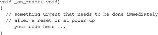
This function will replace an empty place holder that the crt0 code is normally calling before getting to the initialization part. Be careful, though, to make it short and not to make too many assumptions at this point. First, remember that this function will be called every time the PIC32 goes through a reset sequence. Second, apart from the stack, you cannot count on your program functions and global variables to be available and initialized yet!
Exercises
Books
Rony, P., Larsen, D., and Titus, J., The 8080A Bugbook, Microcomputer Interfacing And Programming (Howard W. Sams & Co., Inc, Indianapolis, IN, 1976). This is the book that introduced me to the world of microprocessors and changed my life forever. No high-level language programming here, just the basics of assembly programming and hardware interfacing. (Too bad this book is already considered museum material; see link below.)
Links
www.bugbookcomputermuseum.com/BugBook-Titles.html. A link to the “Bugbooks museum”; 30 years since the introduction of the Intel 8080 microprocessor and it is like centuries have already passed.
http://en.wikipedia.org/wiki/Morse_code. Learn about the Morse code, its history, and its applications.