
Chapter 4: Getting Started with Computer Vision
In the previous chapter, we learned the basics of programming of Python 3, NumPy, matplotlib, and General Purpose Input Output (GPIO). In this chapter, we will focus on the acquisition of images and videos. This chapter has a lot of coding examples that we will be using throughout the book.
In this chapter, we will cover the following topics:
- Exploring image datasets
- Working with images using OpenCV
- Using matplotlib to visualize images
- Drawing geometric shapes with OpenCV and NumPy
- Working with a GUI
- Event handling and a primitive paint application
- Working with a USB webcam
- The Pi camera module
Technical requirements
The code files of this chapter can be found on GitHub at https://github.com/PacktPublishing/raspberry-pi-computer-vision-programming/tree/master/Chapter04/programs.
Check out the following video to see the Code in Action at https://bit.ly/3dtrA2t.
Exploring image datasets
We will need sample images for our computer vision programs with Python and OpenCV. We can find a lot of images online. However, many of those images are under copyright. Most computer vision researchers and professionals use standard image datasets. We prefer to use the following image datasets all the time:
- http://sipi.usc.edu/database/
- http://www.imageprocessingplace.com/root_files_V3/image_databases.htm
- http://www.cvlab.cs.tsukuba.ac.jp/dataset/tsukubastereo.php
Download these datasets. They will be in compressed zip format. Extract them into the ~/book/dataset directory. From this chapter onward, we will write a lot of programs for computer vision that will require images, and we will use the images from these datasets for all our needs. The other option for images is to use a web camera and RPi camera module to capture images, which we will learn about later in this chapter.
Working with images using OpenCV
In this section, we will learn to read and store images using the OpenCV API and Python. All the programs in this book will use the OpenCV library. It can be imported with the following Python 3 statement:
import cv2
The cv2.imread() function reads an image from the disk and stores it in a NumPy ndarray. It accepts two arguments. The first argument is the name of the image file on the disk. The image should either be in the same directory where we are saving the current Python 3 script, or we must pass the absolute path of the image file as an argument to the cv2.imread() function.
The second argument is a flag that specifies the mode in which the image should be read. The flag can have one of the following values:
- cv2.IMREAD_GRAYSCALE: This reads an image from the disk in grayscale mode. The numerical value corresponding to this flag is 0.
- cv2.IMREAD_UNCHANGED: This reads an image from the disk as it is. The numerical value corresponding to this flag is -1.
- cv2.IMREAD_COLOR: This reads the image in color mode, and it is the default value for the argument of the parameter. The numerical value corresponding to this flag is 1. This is the default value of the argument.
The following is the code for reading an image in color mode:
import cv2
img = cv2.imread('/home/pi/book/dataset/4.2.03.tiff', cv2.IMREAD_COLOR)
We can rewrite the last line with the flags as follows:
img = cv2.imread('/home/pi/book/dataset/4.2.03.tiff', 1)
The preceding style of writing code for reading the source images with numerical flags is very simple. So, we will use it throughout the book:
cv2.imshow('Mandrill', img)
cv2.waitKey(0)
cv2.destroyWindow('Mandrill')
The cv2.imshow() function displays an image in a window on the screen. It accepts two arguments. The string that is the name of the window is the first argument, and the NumPy ndarray variable that has the image to be displayed is the second variable.
The cv2.waitKey() function is a function used for binding the events for the keyboard. It accepts an argument, which is the number of milliseconds the function needs to wait to detect the keypress of the keyboard. If we pass it 0, it waits for the press of a key on the keyboard indefinitely. It is the only function in the OpenCV library that can handle the events of the keyboard. We must call it immediately after the call of the cv2.imshow() function. If we do not call it that way, no window for the image will be displayed on the screen as cv2.waitKey() is the only function that fetches and handles events.
The cv2.destroyWindow() function accepts the name of the windows to be destroyed as an argument. When all the windows the current program displays must be destroyed, we use the cv2.destoyAllWindows() function to do this. We will use these functions in almost all of the OpenCV programs throughout this book.
We can also create a window in advance that has a specific name, and then associate an image with that window later in the program when we need it. It is recommended that we create a window in advance before we process an image. The following code snippet demonstrates this:
cv2.namedWindow('Lena', cv2.WINDOW_AUTOSIZE)
cv2.imshow('Mandrill', img)
cv2.waitKey(0)
cv2.destroyWindow('Mandrill')
Let's put it all together to get the following script:
import cv2
img = cv2.imread('/home/pi/book/dataset/4.2.03.tiff', 1)
cv2.imshow('Mandrill', img)
cv2.waitKey(0)
cv2.destroyWindow('Mandrill')
The preceding code imports an image, displays it on the screen, and then waits for a keystroke on the keyboard to close the image window. The following is a screenshot of the output of the preceding code:
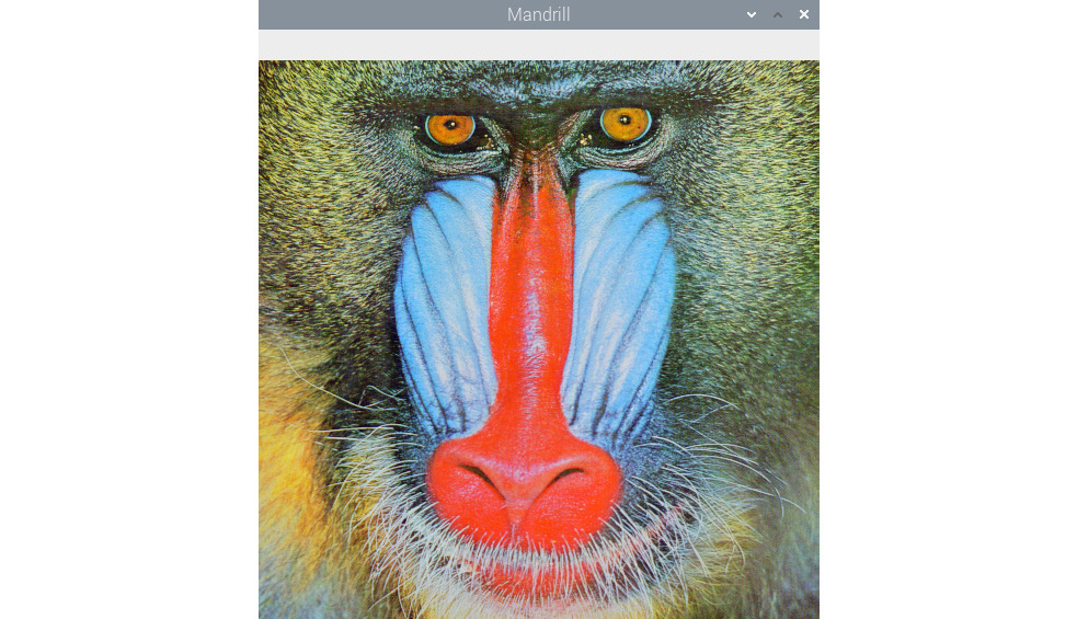
Figure 1: Reading and visualizing a color image with OpenCV
The cv2.imwrite() function saves a NumPy ndarray to a specific path on the disk. The first argument is the string that is the name of the file with which we want to save the image, and the second argument is the name of the NumPy array that has the image. Additionally, the cv2.waitKey() function can detect specific keystrokes on the keyboard. Let's look at a demonstration of both of the functions as follows:
import cv2
img = cv2.imread('/home/pi/book/dataset/4.2.03.tiff', 1)
cv2.imshow('Mandrill', img)
keyPress = cv2.waitKey(0)
if keyPress == ord('q'):
cv2.destroyWindow('Mandrill')
elif keyPress == ord('s'):
cv2.imwrite('test.jpg', img)
cv2.destroyWindow('Mandrill')
Here, the line keyPress = cv2.waitKey(0) saves the value of the keystroke on the keyboard in the keyPress variable. The ord() function accepts a single character and returns an integer that represents the Unicode of the character if it is a Unicode object. Based on the value of the keyPress variable, we can either exit straight away, or exit after saving the image to the disk. For example, if we press the Esc key, the cv2.waitKey() function returns the value of 27.
Using matplotlib to visualize images
Matplotlib is a very robust data visualization library for the Python 3 programming language. It is also capable of visualizing images. It also offers a wide range of options for plotting, and we will learn many of its capabilities in the later chapters of this book. Let's write a program that displays an image with matplotlib that we read in grayscale mode using the OpenCV cv2.imread() function:
import cv2
img = cv2.imread('/home/pi/book/dataset/4.2.03.tiff', 0)
import matplotlib.pyplot as plt
plt.imshow(img)
plt.title('Mandrill')
plt.axis('off')
plt.show()
Note
You can download the example code files from your account at http://www.packtpub.com for all the Packt Publishing books you have purchased. If you purchased this book elsewhere, you can visit http://www.packtpub.com/support and register to have the files emailed directly to you.
In the preceding example, we are reading an image in grayscale mode and displaying it with the matplotlib plt.imshow() function. The following is the output of the preceding program:
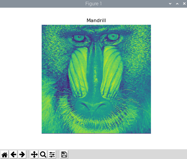
Figure 2: Visualizing a BGR image as an RGB image with matplotlib
I know that the image does not look natural. This is because we are reading the image in grayscale mode and visualizing it with the default colormap. Make the following changes in plt.imshow(), and we will find the output more palatable to our eyes. The following is the output:

Figure 3: Visualizing a grayscale image
This was all about grayscale images.
The cv2.imread() function also works with color images. It reads and saves them as a three-dimensional ndarray of Blue, Green, and Red (BGR) pixels.
However, the matplotlib plt.imshow() function displays NumPy ndarrays as images in the RGB colorspace. If we read an image with the cv2.imread() function in the default BGR format of OpenCV and show it with the plt.imshow() function, the plt.imshow() function will treat the value for the intensity of the blue color as the value of the intensity of the red color and vice versa. This will make the image appear with distorted colors. Make the following change to the preceding code in the respective lines and run the program again:
img = cv2.imread('/home/pi/book/dataset/4.2.03.tiff', 1)
plt.imshow(img)
Make the changes and run the code to see the color image with distorted colors. To solve this issue, we must convert the image read in the BGR colorspace by the cv2.imread() function to the RGB colorspace so that the plt.imshow() function will be able to render it in a fashion that makes sense to the human eyes and brain. We will use the cv2.cvtColor() function for this task, and we will learn about this in more detail later on in this book.
Drawing geometric shapes with OpenCV and NumPy
Let's learn how to draw various geometric shapes using the OpenCV drawing functions. We will also use NumPy here.
The following code imports all the required libraries for this demonstration:
import cv2
import numpy as np
The following code creates an RGB ndarray of all zeros. It is an image in which all the pixels are black:
image = np.zeros((200, 200, 3), np.uint8)
We are using the np.zeros() function to create an ndarray of all zero elements.
We'll start by drawing a line, as it is a simple geometric shape. With the help of the following code, we'll draw a line with coordinates (0, 199) and (199, 0), with red color [(0, 0, 255) in BGR], and with a thickness of 2 pixels:
cv2.line(image, (0, 199), (199, 0), (0, 0, 255), 2)
All the OpenCV functions for drawing have the following common parameters:
- img: This is the image where we need to draw the geometric shapes.
- color: This is passed as a tuple of (B, G, R) to express the colors where the value of the intensity of each color is in between 0 and 255.
- thickness: The default value of the argument for this parameter is 1. For all the shapes that are geometrically closed, such as an ellipse, a circle, and a rectangle, -1 completely fills in the shape with the color specified as an argument.
- LineType: This can have any one of the following three values:
8: Eight-connected lines (this is the default value of the argument for this parameter).
4: Four-connected lines.
cv2.LINE_AA: This stands for anti-aliasing (it is usually used with geometric shapes that have curves such as an ellipse or circle).
The following line of code will help us to draw a rectangle with (20, 20) and (60, 60) as diagonally opposite vertices and the color blue:
cv2.rectangle(image, (20, 20), (60, 60), (255, 0, 0), 1)
The following line of code will help us to draw a circle with the center located at (80, 80), 10 pixels as the radius, and green as the fill color:
cv2.circle(image, (80, 80), 10, (0, 255, 0), -1)
The following line of code will help us to draw a full ellipse with no rotations, a center located at pixels (99, 99), and the lengths of the major and minor axes as 40 pixels and 20 pixels, respectively:
cv2.ellipse(image, (99, 99), (40, 20), 0, 0, 360, (128, 128, 128), -1)
The following code plots a polygon that has four points. It is defined as follows:
points = np.array([[100, 5], [125, 30], [175, 20], [185, 10]], np.int32)
points = points.reshape((-1, 1, 2))
cv2.polylines(image, [points], True, (255, 255, 0))
If we pass False as the value for the third argument in the call of the polylines() function, it joins all the points with the line segments and will not plot a closed shape.
We can also print text in the image using the cv2.putText() function. The following code adds the text to the image with (80, 180) as the bottom-left corner of the text, HERSHEY_DUPLEX as the font with size of text 1, and the color of the text as pink:
cv2.putText(image, 'Test', (80, 180), cv2.FONT_HERSHEY_DUPLEX, 1, (255, 0, 255))
The cv2.putText() function accepts one of the following fonts as an argument:
- FONT_HERSHEY_DUPLEX
- FONT_HERSHEY_COMPLEX
- FONT_HERSHEY_SIMPLEX
- FONT_HERSHEY_PLAIN
- FONT_HERSHEY_SCRIPT_SIMPLEX
- FONT_HERSHEY_SCRIPT_COMPLEX
- FONT_HERSHEY_TRIPLEX
- FONT_HERSHEY_COMPLEX_SMALL
The output image is shown using this familiar snippet of code:
cv2.imshow('Shapes', image)
cv2.waitKey(0)
cv2.destroyAllWindows()
The output of the preceding code is as follows:

Figure 4: Drawing geometric shapes
Note
If the pixels of the geometric shapes overlap, then those pixels will always have the value that is assigned by the latest geometric function. For example, the ellipse overlaps the line and the circle in the preceding figure.
As an exercise, change the values of the arguments passed to all the geometric functions and run the code again to understand the functionality better.
Working with a GUI
By now we are aware of how to create a named window using the call of the OpenCV cv2.namedWindow() function. We will now demonstrate how to create trackbars using the cv2.CreateTrackbar() function, how to associate it with a named window, and how to use those trackbars to choose the value of the color channels in the RGB colorspace. Let's get started with the following code:
import numpy as np
import cv2
def empty(z):
pass
image = np.zeros((300, 512, 3), np.uint8)
cv2.namedWindow('Palette')
cv2.createTrackbar('B', 'Palette', 0, 255, empty)
cv2.createTrackbar('G', 'Palette', 0, 255, empty)
cv2.createTrackbar('R', 'Palette', 0, 255, empty)
while(True):
cv2.imshow('Palette', image)
if cv2.waitKey(1) == 27 :
break
blue = cv2.getTrackbarPos('B', 'Palette')
green = cv2.getTrackbarPos('G', 'Palette')
red = cv2.getTrackbarPos('R', 'Palette')
image[:] = [blue, green, red]
cv2.destroyWindow('Palette')
In the preceding code, we first create an image with all the pixels colored black and a named window with the name of Palette. The cv2.createTrackbar() function creates a trackbar. The following is the list of arguments accepted by this function:
- Name: The name of the trackbar.
- Window_name: The name of the output window the trackbar is to be associated with.
- Value: The initial value of the slider of the trackbar when it is created.
- Count: The maximum value of the slider of the trackbar (the minimum value of the slider is always 0).
- Onchange(): This function is called when we change the position of the slider of the trackbar.
We have created a function and named it empty(). We do not intend to perform any activity when we change the slider of the trackbar. We are just passing the call of this function to the cv2.createTrackbar() function. The call of the cv2.getTrackbarPos() function returns the most recent position of the slider of the trackbar. Based on the positions of the sliders of all three trackbars, we set the color of the palette. The application closes when we press the Esc key on the keyboard. The application we created should look like this:
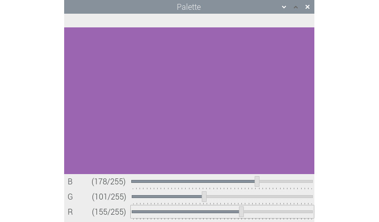
Figure 5: A BGR color palette
OpenCV also offers a lot of functionality to handle events. We will explore that next.
Event handling and a primitive paint application
A variety of keyboard and mouse events are recognized by OpenCV. We can view the list of events by following these instructions. Open the Python 3 Interpreter in interactive mode by running the python3 command on Command Prompt, and then run the following statements:
>>> import cv2
>>> events = [i for i in dir(cv2) if 'EVENT' in i]
>>> print(events)
It will show the following output:
['EVENT_FLAG_ALTKEY', 'EVENT_FLAG_CTRLKEY', 'EVENT_FLAG_LBUTTON', 'EVENT_FLAG_MBUTTON', 'EVENT_FLAG_RBUTTON', 'EVENT_FLAG_SHIFTKEY', 'EVENT_LBUTTONDBLCLK', 'EVENT_LBUTTONDOWN', 'EVENT_LBUTTONUP', 'EVENT_MBUTTONDBLCLK', 'EVENT_MBUTTONDOWN', 'EVENT_MBUTTONUP', 'EVENT_MOUSEHWHEEL', 'EVENT_MOUSEMOVE', 'EVENT_MOUSEWHEEL', 'EVENT_RBUTTONDBLCLK', 'EVENT_RBUTTONDOWN', 'EVENT_RBUTTONUP']
We can write code to handle a couple of these events and create a simple and primitive paint application. Let's import the required libraries using the following code:
import cv2
import numpy as np
Create a black background and a named window:
windowName = 'Drawing'
img = np.zeros((512, 512, 3), np.uint8)
cv2.namedWindow(windowName)
Define a custom function, called draw_circle():
def draw_circle(event, x, y, flags, param):
if event == cv2.EVENT_LBUTTONDBLCLK:
cv2.circle(img, (x, y), 40, (0, 255, 0), -1)
if event == cv2.EVENT_MBUTTONDOWN:
cv2.circle(img, (x, y), 20, (0, 0, 255), -1)
if event == cv2.EVENT_LBUTTONDOWN:
cv2.circle(img, (x, y), 30, (255, 0, 0), -1)
In the preceding definition, we are drawing circles using various properties on the mouse events. Now, let's call the setMouseCallback() function and pass it the name of the window and the draw_circle() function as arguments:
cv2.setMouseCallback(windowName, draw_circle)
This call will bind the draw_circle() function with the given window's mouse events. Finally, we write the loop for displaying the image window and exit when the Esc key is pressed:
while(True):
cv2.imshow(windowName, img)
if cv2.waitKey(20) == 27:
break
cv2.destroyAllWindows()
Run the entire code and you will see the following output:

Figure 6: A simple paint application
As we have programmed the left, middle, and down button's double-click events, depending on these events and the location of the cursor, your output will be different.
We will use the drawing API in OpenCV sparingly in this book. The functionality that we will use the most throughout this book is related to the webcam. The next section is dedicated to the interfacing and use of the webcam with OpenCV and the Raspberry Pi.
Working with a USB webcam
Cameras are image sensors. That said, analog cameras and motion film cameras record images on films. Digital cameras have digital sensors to capture the image and these are stored in electronic formats on various types of storage mediums. A subset of digital cameras is USB webcams. These webcams, as their name indicates, can be interfaced to a computer via USB, hence the name, USB webcam. In this section, we will learn about the interfacing of USB webcams with the Raspberry Pi and programming using shell scripts, Python 3, and OpenCV in detail.
Note
All these webcams work with Raspberry Pi boards. However, a few webcams may have issues. The https://elinux.org/RPi_USB_Webcams URL has a list of many webcams and details regarding compatibility.
All the programs in this book are tested with the RPi 4B and a Logitech C310 webcam. You can view its product page at https://www.logitech.com/en-in/product/hd-webcam-c310.
Attach the USB webcam to the RPi using the USB port on the board and run the following command in the Terminal:
lsusb
The output of this command shows the list of all the USB devices connected to the Linux computer. The following is the output shown on my RPi board:
pi@raspberrypi:~/book/chapter04 $ lsusb
Bus 002 Device 001: ID 1d6b:0003 Linux Foundation 3.0 root hub
Bus 001 Device 005: ID 046d:081b Logitech, Inc. Webcam C310
Bus 001 Device 004: ID 1c4f:0002 SiGma Micro Keyboard TRACER Gamma Ivory
Bus 001 Device 003: ID 046d:c077 Logitech, Inc. M105 Optical Mouse
Bus 001 Device 002: ID 2109:3431 VIA Labs, Inc. Hub
Bus 001 Device 001: ID 1d6b:0002 Linux Foundation 2.0 root hub
As you can see in the preceding output, the second entry corresponds to the USB webcam that is connected to the RPi board. We can also see a USB mouse and a USB keyboard connected to the RPi board.
Capturing images with the webcam
Let's now demonstrate how to capture images with the USB webcam attached to the RPi. We can install the fswebcam utility by running the following command on the terminal:
sudo apt-get install fswebcam
Once we install it, we can run the following command to capture a photograph with the USB webcam:
fswebcam -r 1280x960 --no-banner ~/book/chapter04/camtest.png
This command captures an image with a resolution of 1280 x 960 pixels using the USB webcam connected to the RPi. The command-line --no-banner argument passed to the command disables the banner for the timestamp. The image is saved with the filename passed as the last argument. If we run this command repeatedly, the new photograph that is captured will be overwritten to the same file. So, next time we run the command, we must pass a different filename as a parameter to the command if we do not want to overwrite the earlier file.
Note
If you want to read more about fswebcam (or any Linux command for that matter), you can run the man fswebcam command on Command Prompt.
Timelapse photography
Capturing photographs at regular intervals with a camera and playing them back at a higher frame rate than they were captured at is known as timelapse photography. For example, if we capture photographs at the rate of one photograph per minute for 10 hours, we will have 600 photographs. If we stitch all of them into a video and play it back with a frame rate of 30 photos per second, we will have a 20-second video. This video is known as a timelapse video. We can use the RPi board with a USB webcam for this. We have already learned how to use a USB webcam with an RPi board to do this. We have also learned the usage of the fswebcam utility. We will write a script that captures images with timestamps in the filename. Then, we will add this script to the crontab to execute it at regular intervals. Cron is a job schedular for Unix-like OSes. It is driven by a file named crontab (cron table). It is a Unix configuration file that specifies the scripts or programs to be run at a particular time or interval.
Let's create a shell script with the name of timelapse.sh and save it in a location of our choice on the disk. We must add the following code to the script file and save it:
#!/bin/bash
DATE=$(date +"%Y-%m-%d_%H%M")
fswebcam -r 1280x960 --no-banner Image_$DATE.png
Let's make the mode of the script executable by running the following command:
chmod +x timelapse.sh
This script takes a photograph using the USB webcam and then saves it to a location in the disk. The captured image has a new filename every time because the filename has a timestamp when the image is captured. We must execute this script manually once to make sure it works without any problem and that it captures an image in the filename format of Image_<timestamp>.png.
Once the script is checked for any issues, it must be executed at regular intervals to capture images for the timelapse sequence. For that to happen, we must add it to the crontab. The syntax for an entry in the crontab is as follows:
1 2 3 4 5 /location/command
Let's check the meaning of the terms in the syntax:
- 1: Position of minutes (can range from 0-59)
- 2: Position of hours (can range from 0-23)
- 3: Position of the day of the month (can range from 0-31)
- 4: Position of the month (can range from 0-12 [1 for January])
- 5: Position of the day of the week (can range from 0-7 [7 or 0 for Sunday])
- /location/command: Script or command name to schedule
Therefore, the entry for the crontab to run the timelapse.sh script once every minute is as follows:
* * * * * /home/pi/book/chapter04/timelapse.sh 2>&1
Open the crontab of user pi using the following command:
crontab –e
This will open the crontab. When we execute this for the very first time on our RPi, it will ask which text editor to choose. Choose the Nano option by entering 1. Add the preceding line to the crontab as an entry. Then save and exit it.
Once we exit the crontab, it will show us the following message:
crontab: installing new crontab
Once we do this, our setup for the timelapse is live. We can change the settings in the entry of the crontab to the settings of our choice. To run the script every 5 minutes, use the following:
*/5 * * * * /home/pi/book/chapter04/timelapse.sh 2>&1
To run the script every 2 hours, use the following:
* */2 * * * /home/pi/book/chapter04/timelapse.sh 2>&1
Once we capture all the images for our timelapse, we must encode them in a video that has a frame rate of 24, 25, 29, or 30 frames per second (FPS). These are all the standard frame rates. I prefer to encode the video using 30 FPS. Raspberry Pi is a slow computer for video editing. It is recommended that you copy the images to a faster computer to encode the video. For Linux computers, I prefer to use the command-line MEncoder utility. We can use the other utilities or video editing tools for this task too. The following are the steps needed to create a timelapse video with MEncoder on the Raspberry Pi or any other Linux computer:
- Install MEncoder using the following command on Command Prompt:
sudo apt-get install mencoder -y
- Navigate to the output directory by issuing the following command:
cd /home/pi/book/chapter04
- Create a list of the images to be used in our timelapse sequence using the following command:
ls Image_*.png > timelapse.txt
- Finally, we can use the following command to create a nice timelapse video:
mencoder -nosound -ovc lavc -lavcopts vcodec=mpeg4:aspect=16/9:vbitrate=8000000 -vf scale=1280:960 -o timelapse.avi -mf type=jpeg:fps=30 mf://@timelapse.txt
This creates the video with the timelapse.avi filename in the current directory where we are running the command (also known as the present working directory). The frame rate of the video will be 30 FPS. Very soon, we will learn how to play this video file.
Webcam video recording
We can use the USB webcam connected the RPi to record live videos using the command-line ffmpeg utility. We can install the ffmpeg utility using the following command:
sudo apt-get install ffmpeg
We can use the following command to record a video:
ffmpeg -f video4linux2 -r 25 -s 544x288 -i /dev/video0 test.avi
We can terminate the operation of recording the video by pressing Ctrl + C on the keyboard.
We can play the video using the command-line omxplayer utility. It comes preinstalled with the latest release of Raspbian, so we do not have to install it separately. To play a file with the timelapse.avi filename, navigate to the location of the video file using Command Prompt and run the following command:
omxplayer timelapse.avi
We can even double-click on the video files in the Raspbian GUI to play them with VLC media player.
Capturing images with the webcam using Python and OpenCV
Let's learn how to capture images with the webcam connected to the RPi using Python 3 and OpenCV:
import cv2
import matplotlib.pyplot as plt
cap = cv2.VideoCapture(0)
if cap.isOpened():
ret, frame = cap.read()
else:
ret = False
print(ret)
print(type(frame))
cv2.imshow('Frame from Webcam', frame)
cv2.waitKey(0)
cap.release()
cv2.destroyAllWindows()
In the previous code snippet, the cv2.VideoCapture() function creates an object to capture the video using the webcam connected to the RPi. The argument for it could either be the index of the video device or a video file. In this case, we are passing the index of the video device, which is 0. If we have more cameras connected to the RPi board, we can pass the appropriate device index based on which camera is chosen. If we have connected only one camera, then we just pass 0.
We can find out the number of cameras and device indexes associated with those cameras by running the following command:
ls -l /dev/video*
The cap.read() function returns a Boolean ret value and a NumPy frame ndarray that contains the image it captured. If the operation of capturing the image is successful, then ret will have a Boolean value of True; otherwise, it will have a Boolean value of False. The preceding code captures an image using the USB camera identified by /dev/video0, displays it on the screen, and then finally saves it to the disk with the filename test.png. The cap.release() function releases the video capture device.
Live videos with the webcam using Python and OpenCV
We can use the previous code with a few modifications to display a live video stream from a USB webcam:
import cv2
windowName = "Live Video Feed"
cv2.namedWindow(windowName)
cap = cv2.VideoCapture(0)
if cap.isOpened():
ret, frame = cap.read()
else:
ret = False
while ret:
ret, frame = cap.read()
cv2.imshow(windowName, frame)
if cv2.waitKey(1) == 27:
break
cv2.destroyAllWindows()
cap.release()
The previous code shows the live video captured by the webcam until we press the Esc key on the keyboard. The preceding code example is the template for the all the code examples for the processing of live videos captured using the USB webcam connected to the RPi board.
Webcam resolution
We can read the properties of the webcam using cap.get(). We must pass 3 to get the width and 4 to get the height. We can also set the properties with cap.set() in the same way. The following code demonstrates this:
import cv2
windowName = "Live Video Feed"
cv2.namedWindow(windowName)
cap = cv2.VideoCapture(0)
print('Width : ' + str(cap.get(3)))
print('Height : ' + str(cap.get(4)))
cap.set(3, 5000)
cap.set(4, 5000)
print('Width : ' + str(cap.get(3)))
print('Height : ' + str(cap.get(4)))
if cap.isOpened():
ret, frame = cap.read()
else:
ret = False
while ret:
ret, frame = cap.read()
cv2.imshow(windowName, frame)
if cv2.waitKey(1) == 27:
break
cv2.destroyAllWindows()
cap.release()
In the preceding code, we are setting both the height and width to 5000. The webcam does not support this resolution, so the height and width will both be set to the maximum resolution supported by webcam. Run the preceding code and observe the output printed in Command Prompt.
FPS of the webcam
We can retrieve the FPS of the webcam we are using, and we can also calculate the actual FPS ourselves. The FPS that we retrieve as a property of the webcam and the calculated FPS could be different. Let's check this. Import all the required libraries:
import time
import cv2
Next, initiate an object for the video capture:
cap = cv2.VideoCapture(0)
We can fetch the camera resolution using cap.get(), as follows:
fps = cap.get(cv2.CAP_PROP_FPS)
print("FPS with CAP_PROP_FPS : {0}".format(fps))
Then, we will capture 120 frames continuously. We record the time before and after the operation as follows:
num_frames = 120
print("Capturing {0} frames".format(num_frames))
start = time.time()
for i in range(0, num_frames):
ret, frame = cap.read()
end = time.time()
Then, finally, we compute the actual time required to capture the frames, and we can calculate the FPS using the following formula:
The code is as follows:
seconds = end - start
print("Time taken : {0} seconds".format(seconds))
fps = num_frames / seconds
print("Actual FPS calculated : {0}".format(fps))
cap.release()
Run the entire program, and the output should be like this:
FPS with CAP_PROP_FPS : 30.0
Capturing 120 frames
Time taken : 9.86509919166565 seconds
Actual FPS calculated : 12.164094619685105
We usually never get the FPS retrieved from the properties due to hardware limitations.
Saving webcam videos
We use the OpenCV cv2.VideoWriter() function to save the live USB webcam stream to a video file on the disk. The following code demonstrates this:
import cv2
windowName = "Live Video Feed"
cv2.namedWindow(windowName)
cap = cv2.VideoCapture(0)
filename = 'output.avi'
codec = cv2.VideoWriter_fourcc('W', 'M', 'V', '2')
framerate = 30
resolution = (640, 480)
Output = cv2.VideoWriter(filename, codec,
framerate, resolution)
if cap.isOpened():
ret, frame = cap.read()
else:
ret = False
while ret:
ret, frame = cap.read()
Output.write(frame)
cv2.imshow(windowName, frame)
if cv2.waitKey(1) == 27:
break
cv2.destroyAllWindows()
cap.release()
In the preceding code, the call of the cv2.VideoWriter() function accepts the arguments for the following parameters:
- filename: This is the name of the video file to be written on the disk.
- fourcc: This means the four-character code. We use the cv2.VideoWriter_fourcc() function for this. This function accepts a four-character code as an argument. A few supported four-character code formats are WMV2, MJPG, H264, WMV1, DIVX, and XVID. You can read more about four-character codes at http://www.fourcc.org/codecs.php.
- framerate: This refers to the FPS of the video to be captured.
- resolution: This is the resolution in pixels with which the video is to be captured and saved on the disk.
The preceding code records the video until the Esc key on the keyboard is pressed, and then saves it on the disk with the filename specified in the argument of the cv2.VideoWriter() function.
Playing back the video with OpenCV
We can easily play back the video using OpenCV. We just need to pass the name of the video file to the VideoCapture() function in place of the index of the webcam (which is 0, in our case). In order to decide the FPS for the playback, we need to pass the appropriate argument to the call of the waitKey() function. Suppose we want to play back the video at 25 FPS, then the argument to be passed can be calculated with the 1000/25 = 40 formula. We know that waitKey() waits for the number of milliseconds we pass to it as an argument. And, a second has 1,000 milliseconds, hence the formula. For 30 FPS, this will be 33.3. Let's take a look at the following code:
import cv2
windowName = "OpenCV Video Player"
cv2.namedWindow(windowName)
filename = 'output.avi'
cap = cv2.VideoCapture(filename)
while(cap.isOpened()):
ret, frame = cap.read()
if ret:
cv2.imshow(windowName, frame)
if cv2.waitKey(33) == 27:
break
else:
break
cv2.destroyAllWindows()
cap.release()
The preceding program plays the video file with a frame rate of 30 FPS and terminates after the last frame or when we press the Esc key on the keyboard. You might want to play with the program and try to change the output frame rate by changing the value of the argument to the call of the cv2.waitKey() function.
In the next section, we will study the Pi camera module in more detail.
The Pi camera module
A webcam uses a USB port for interfacing with a computer. That is why we can use it with any computer that has a USB port. The Pi camera modules (also known as Pi camera boards) are sensors that are specifically manufactured for RPi boards. The Raspberry Pi Foundation and many other third-party manufacturers produce them. Basically, they are PCBs with a specialized image sensor on them (that is why they are known as Pi camera boards).
The Pi camera board does not have a USB port. It connects to Raspberry Pi through a Camera Serial Interface (CSI) interface strip. Because of the dedicated connection that uses CSI, the performance of a Pi camera board is much better than a USB webcam. We can use Python 3 with a Pi camera module connected to the RPi to capture videos and still images programmatically. It is not possible to use the Pi camera board with any computer other than a Raspberry Pi (and a select few single-board computers that support connectivity with the camera module).
The camera modules are offered in two varieties—the camera module and the NoIR module. The camera module is great for daytime and well-illuminated scenes. The NoIR module is essentially a camera module without the Infrared (IR) filter. It does not produce impressive results during the daytime or in well-illuminated scenes. However, it is great in low light or in dark scenes when used with IR light.
You can find the latest versions of both of these modules at their product pages at https://www.raspberrypi.org/products/camera-module-v2/ and https://www.raspberrypi.org/products/pi-noir-camera-v2/. There have been generations of these camera boards/modules, V1 and V2. The V1s are of 5 megapixels and are no longer produced. The V2s are the latest and they have an 8-megapixel sensor. You can read about the differences between them at https://www.raspberrypi.org/documentation/hardware/camera/.
All the cameras come with a detachable ribbon that can be used to connect the camera to the RPi boards using the Camera Serial Interface (CSI) port. The following is a photograph of a camera module and the ribbon:

Figure 7: The Pi camera board and the CSI interface ribbon
We must connect the blue end to the CSI port of the RPi board and the other end to the camera board.
The RPi Zero and RPi Zero W are equipped with smaller CSI ports. There are separate ribbons for them. The following is a photograph of such a ribbon:

Figure 8: Mini CSI ribbon
The following is a photograph of a Pi NoIR board connected to an RPi Zero board:

Figure 9: Pi NoIR with RPi Zero
I have already mentioned that the Pi Camera V1 is not in production anymore. You will find a lot of these V1 modules at low prices (from $5 to $7) online. Additionally, there are other manufacturers that produce similar boards that are compatible with RPi CSI ports. They are also available online for purchase.
Capturing images and videos with the raspistill and raspivid utilities
In order to capture still photographs and motion videos using the camera module of the RPi, we need to use the command-line raspistill and raspivid utilities. To capture an image, run the following command:
raspistill -o test.png
This command captures and saves an image in the current directory with the test.png filename.
To capture a 20-second video with the RPi camera module, run the following command in Command Prompt:
raspivid -o vid.h264 -t 20000
Unlike the fswebcam and ffmpeg utilities, the raspistill and raspivid utilities do not write anything to Command Prompt. So, we must check the current directory for any output. Additionally, we can run the following command after executing the raspistill and raspivid utilities to check whether these commands have been executed successfully:
echo $?
Many computers and OSes cannot play videos in the H.264 format directly. For that, we need to wrap them in the popular and widely supported MP4 format. To do this, we need a command-line utility known as MP4Box. We can install it by running the following command on Command Prompt:
sudo apt install -y gpac
Now, record an H.264 video:
raspivid -t 30000 -w 640 -h 480 -fps 25 -b 1200000 -p 0,0,640,480 -o pivideo.h264
Wrap it in the MP4 format and remove the original file (if you want to), as follows:
MP4Box -add pivideo.h264 pivideo.mp4
rm pivideo.h264
Just like the fswebcam utility, the raspistill utility can also be used to capture a timelapse sequence. In the timelapse.sh shell script that we prepared earlier, replace the line that calls the fswebcam utility with the appropriate raspistill command to record a photograph of a timelapse sequence. Then, use the MEncoder utility on the RPi or any other Linux computer to create a nice timelapse video.
Using picamera with Python 3
picamera is a Python package that provides a programming interface to the RPi camera module. The most recent version of Raspbian has picamera installed. If you do not have it installed, you can install it by running the following commands:
pip3 install picamera
pip3 install "picamera[array]"
The following program quickly demonstrates the basic usage of the picamera module to capture a picture:
from time import sleep
from picamera import PiCamera
camera = PiCamera()
camera.resolution = (1024, 768)
camera.start_preview()
sleep(2)
camera.capture('test.png')
We are importing the time and picamera libraries in the first two lines. The call to the start_preview() function starts the preview of the scene to be captured. The sleep(5) function waits for 5 seconds before the capture() function captures and saves the photo to the file specified in its arguments.
The picamera module offers the capture_continuous() function for timelapse photography. Let's demonstrate how to use it in the following program:
camera = PiCamera()
camera.start_preview()
sleep(2)
for filename in camera.capture_continuous('img{counter:03d}.png'):
print('Captured %s' % filename)
sleep(1)
In the preceding code, the capture_continuous() function records the photographs for a timelapse sequence with the Pi camera board connected to the RPi. In this way, we do not have to depend on the crontab utility to continuously call the script because we can control it better programmatically.
We can record videos by using the start_recording(), wait_recording(), and stop_recording() functions, as follows:
import picamera
camera = picamera.PiCamera()
camera.resolution = (320, 240)
camera.start_recording('my_video.h264')
camera.wait_recording(5)
camera.stop_recording()
We can add text to the images as follows:
from time import sleep
from picamera import PiCamera
camera = PiCamera()
camera.resolution = (1024, 768)
camera.start_preview()
camera.annotate_text = 'Hello World!'
sleep(2)
camera.capture('test.png')
We can store an image in a three-dimensional NumPy array as follows:
import time, picamera
import numpy as np
with picamera.PiCamera() as camera:
camera.resolution = (320, 240)
camera.framerate = 24
time.sleep(2)
output = np.empty((240, 320, 3), dtype=np.uint8)
camera.capture(output, 'rgb')
print(type(output))
We can also store the image captured in a NumPy array that is compatible with the OpenCV image format (BGR), as follows:
import time, picamera
import numpy as np
with picamera.PiCamera() as camera:
camera.resolution = (320, 240)
camera.framerate = 24
time.sleep(2)
image = np.empty((240 * 320 * 3, ), dtype=np.uint8)
camera.capture(image, 'bgr')
image = image.reshape((240, 320, 3))
print(type(image))
This stores the image in OpenCV's preferred BGR format. We can use the cv2.imshow() function to display this image.
Using the RPi camera module and Python 3 to record videos
We have already learned how to record a video with a USB webcam connected to RPi and the combination of Python 3 and OpenCV. I have noticed that the same code works for the RPi camera module too. We just need to connect the RPi camera module to the RPi and disconnect the USB webcam in order for the code to work with the RPi camera module and record videos using the code. Please go ahead and give it a try!
Summary
In this chapter, we learned how to work with images and videos. We also learned how to capture images with a USB webcam and RPi camera board. We also learned the basics of GUIs and the event handling functionality offered by OpenCV. We have gained good hands-on experience of shell and Python 3 programming. We will be using the image and video acquisition and handling techniques that we have learned here throughout the book.
In the next chapter, we will learn about the basics of image processing and how to write programs with NumPy and OpenCV.s