3 Historic Milestones in Solar and Infrared Radiation Measurement
To measure is to know.
Lord Kelvin
(1824–1907)
3.1 Introduction
Abilities to measure solar and infrared radiation have developed through centuries of scientific discovery and engineering applications. Historically, measurements have played a critical role in the development of accepted physical laws. Today, solar and infrared radiation measurements are particularly important for advancing atmospheric physics, developing renewable energy technologies, and understanding climate change. The goal of improving data accuracy is common to the development of instrumentation for measuring solar and infrared radiation. This chapter provides a selective account of important solar and infrared radiation observations and instrumentation developments.
3.2 Earliest Observations of the Sun and The Nature of Light
Sunspots and their cyclic behavior have long been an interest of scientific observation. The invention of the telescope in the early seventeenth century provided the capability to determine that the dark spots seen on the face of the sun, noticed as early as the fourth century B.C.E., were associated with the sun itself (Eddy,1976). In addition to viewing the number of sunspots, the early telescopes provided improvements to observations of the faculae (bright areas on the sun’s surface that typically occur before a sunspot) size, shape, location, and most of the other observational detail recorded today. In 1848, a number of European observatories began regular observations using a standard scheme developed by Rudolf Wolf (Waldmeier, 1961). Combined with future efforts to standardize measurement practices, the work started by Wolf produced the most reliable historical record of sunspot numbers in the nineteenth century.
In 1666, Sir Isaac Newton discovered the spectral distribution of sunlight using glass prisms to display the visible spectrum in a darkened room. He also developed the corpuscular theory of light as a means of explaining propagation in a straight line and the property of specular reflection from mirror-like surfaces. Other discoveries in the seventeenth century include the law of refraction by Willebord Snell and the description of light diffraction, discovered independently by Francesco Grimaldi and Robert Hooke (Coulson, 1975). The electromagnetic character of visible radiation would not be discovered for another two centuries.
The measurement of direct solar radiation, the amount of “beam” radiation from the direction of the sun, is essential for understanding the total solar irradiance (TSI) output from the sun. Formerly known as the solar constant, determining the mean value of TSI and its slight variability continues to be the subject of research in astronomy, atmospheric physics, climate change, renewable energy technology development, and other applications. In 1837, Claude Servais Mathias Pouillet produced the first successful research on TSI measurements and introduced the term pyrheliometer from the Greek fire, sun, and measure (Crova, 1876).
In 1913, Charles Greeley Abbot and Loyal Blaine Aldrich at the Smithsonian Institution developed the first radiometer designed for measuring global horizontal irradiance (downwelling total hemispheric radiation from the sun and sky). Using the Greek words for fire, above, and a measure, Abbot and his colleagues named the pyranometer for its ability to measure solar heat from above.* Intended to serve as a standard instrument for solar radiation measurements, details of the design were given by Abbot and Aldrich (1916).
Other notable advances in understanding and measuring optical radiation are listed in Table 3.1, and more detailed descriptions of selected instruments are presented in this chapter.
3.3 Nineteenth-Century Radiometers
3.3.1 POUILLET'S PYRHELIOMETER (1837)
As previously introduced, this instrument was the first to be called a pyrheliometer and was designed as a calorimeter for measuring solar energy. The radiation receiver was a water-filled cylindrical vessel with a blackened absorbing surface aligned perpendicular (normal) to the sun as shown in Figure 3.1. The other surfaces of the cylindrical vessel were silvered to reduce the heat exchange between the receiver and the atmosphere. The receiver fluid temperature was measured with a thermometer in direct contact. The cylinder was rotated about the solar alignment axis to provide mixing of the calorimeter fluid (later changed to mercury). Measurements of direct normal irradiance (DNI) were based on alternating 5-minute periods of aligning the blackened receiver surface normal to and away from the sun. The corresponding temperature rise and fall, the heat capacity of the calorimeter, the total heat received per unit of surface, and unit of time could be computed. From his clear-sky measurements, Pouillet estimated the TSI to be 1227 Wm–2 (1.76 cal cm–2 min–1) (Coulson, 1975) or about 10% lower than the currently accepted value of 1366 Wm–2.
* In 1961, in the second edition of the “Guide to Meteorological Instrument and Observing Practices,” the World Meteorological Organization first recommended the use of the term pyranometer for hemispherical measurements to replace the more commonly used terminology 180° pyrheliometer.
TABLE 3.1
Highlights of Optical Radiation Measurement
|
|

Source: After Coulson, K. L., Solar and Terrestrial Radiation, Methods and Measurements, Academic Press, New York, 1975.
3.3.2 CAMPBELL-STOKES SUNSHINE RECORDER (1853, 1879)
Although this instrument is not a radiometer, this device and some later variants remain in use today for measuring bright sunshine duration. These observations can then be used to estimate daily amounts of solar irradiation (Iqbal, 1983). J. F. Campbell invented his burning sunshine recorder in 1853 by using a glass ball filled with water.
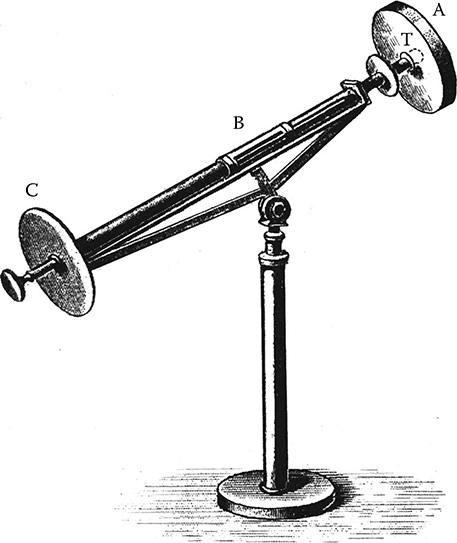
FIGURE 3.1 Pouillet’s pyrheliometer—1837. Direct normal irradiance measurements were based on the temperature changes of the water-filled blackened cylindrical receiver resulting from alternating exposure to the sun and the sky at 5-minute intervals. The end of the thermometer (T) was inserted into the receiver (A) and positioned for reading (B) ahead of the alignment disc (C). (After Fröhlich, C., Metrologia, 28, 1991.)
This spherical lens was placed inside a white stone bowl (later mahogany wood) with a 4-inch diameter surface painted with an oil paint or varnish and engraved with hour lines. During periods when the solar disk was free of clouds or dense haze, the concentrated solar radiation melted the paint (burned the mahogany). The total length of the bright sunshine burns was compared with the total day length to compute percent-possible bright sunshine. Later, a solid glass sphere replaced the water-filled ball to allow operation in freezing conditions. In 1879, Sir G. G. Stokes significantly modified the Campbell sunshine recorder to assume its present form (Figure 3.2). The solid glass sphere is supported by a metal structure that holds specially treated paper strips with precise hourly and subhourly markings. The strips are available in three different lengths: one for summer, winter, and spring/fall periods. Daily, a single card is inserted and precisely registered using a metal pin. The treated paper is stable over a range of humidity levels, including effects of precipitation, allowing the paper to burn when direct normal irradiance levels exceed 210 Wm–2. In 1962, the Commission for Instruments and Methods of Observation (CIMO) of the World Meteorological Organization (WMO) adopted the Campbell–Stokes sunshine recorder as a standard of reference (WMO, 2008). In 1966, the analysis of bright sunshine data from 233 measurement stations and solar radiation measurements from an additional 668 stations were used to produce the first set of monthly world maps of the daily mean total solar radiation on a horizontal surface (Löf, Duffie, and Smith, 1966).

FIGURE 3.2 Campbell–Stokes sunshine recorder continues to provide measurements of bright sunshine duration at several locations around the world. Sensitized recording paper is available in three lengths corresponding to the season of measurement.
Routine measurements of bright sunshine duration using the Campbell–Stokes instrument continue to the present day. These data are included in the records maintained by the World Radiation Data Center (http://wrdc.mgo.rssi.ru/).
3.3.3 Ångström Electrical Compensation Pyrheliometer (1893)
Unlike previous designs based on calorimetry, this instrument was the first to equate electrical power with solar irradiance. Developed by Knut Ångström in the late nineteenth century, this pyrheliometer was recognized for its reliability and accuracy (Ångström, 1893, 1899). With only minor design developments based mostly on improved electrical measurement devices, the Ångström pyrheliometer remains in service today as a primary reference instrument for many solar measurement laboratories. The design uses two strips of Manganin* foil painted on one side with Parson’s optical black lacquer. The strips are mounted side by side at the base of a collimator tube and aligned with two rectangular apertures at the front of the instrument (Figure 3.3). A thermojunction is attached to the back of each receiver strip. Electrical leads from the strips and the thermojunctions are connected to the instrument controls. The operator controls a reversible shutter at the front of the collimator to alternately shade and unshade each of the strips at 90-second intervals. In operation, the shaded strip is heated by a known electrical current to the same temperature as the exposed strip. The rate of energy absorption by the exposed strip (solar heating) is thermoelectrically compensated by the rate of energy supplied electrically to the shaded strip (electrical heating). The thermojunctions attached to the back of each strip are used to monitor their temperature equivalence using a galvanometer or digital null detector. Observations of solar irradiance consist of a series of shade–unshade measurements in which each strip is alternately exposed and shaded. The direct normal irradiance is determined from the equivalence of radiant and electrical power:
* Manganin is an alloy of typically 86% copper, 12% manganese, and 2% nickel.
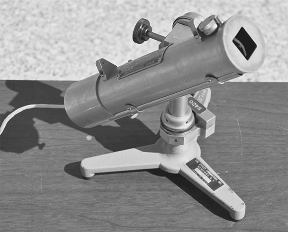
FIGURE 3.3 Ängström electrical compensation pyrheliometer continues to serve as a reference instrument for some countries. This unit was operated during the Eleventh International Pyrheliometer Comparisons at the Physikalisch-Meteorologisches Obseratorium Davos, World Radiation Center in 2010.
where
DNI = direct normal irradiance (Wm–2)
a = absorptance of the receiver strip per unit length
b = width of the receiver strip [cm]
C = a constant based on measurement units (9,995.175)
r = resistance of the receiver strip per unit length (ohms/cm)
I = electric current through the shaded strip (amperes)
In practice, the instrument manufacturer supplied a constant K defined as
to simplify the irradiance determination
The instrument functioned as the European absolute reference beginning in 1905 and ended in 1956 with the adoption of the International Pyrheliometric Scale (IPS 1956) that resolved the differences with the Smithsonian scale of 1913 (Fröhlich, 1991).
3.3.4 CALLENDAR PYRANOMETER (1898)
Invented in 1898 by H. L. Callendar, this early example of a pyranometer was at the time called a bolometric sunshine receiver. An improve version was available in 1905 (Callendar and Fowler, 1906). The instrument used four platinum wire grids wound on strips of mica to form an electrical resistance thermometer. As shown in Figure 3.4, one pair of grids was painted black to enhance the absorption of solar radiation, and the other pair was left as reflecting platinum metal. The checkerboard receiver had an area of about 33.6 cm2 and was mounted in a protective evacuated glass bulb with an outside diameter of about 9.1 cm (Coulson, 1975). The temperature difference between the pairs of grids when exposed to sunlight was proportional to the incoming solar radiation. The popularity of this early pyranometer was due in large part to the integrated data-recording mechanism. A self-adjusting Wheatstone bridge with a pen and recording drum produced an ink trace of the temperature difference in the receiver pairs with time. A calibration factor was supplied with each instrument to convert the recorded data into global irradiance. The Callendar pyranometer enjoyed considerable popularity during the first two decades of the twentieth century. An example of this pyranometer was used at the University of Cambridge School of Botany for more than 50 years and agreed within 1% (more specifically, the correlation coefficient was 0.99) when compared with the British Meteorological Office pyranometer (Beaubien, Bisberg, and Beaubien, 1998). The U.S. Weather Bureau used this instrument from 1908 until the last unit was removed from service in 1941 (Hand, 1941).

FIGURE 3.4 The Callendar pyranometer was a successful all-weather design based on platinum resistance thermometry. One of the blackened receiver sections has lifted from the detector surface.
3.3.5 ANGSTROM TULIPAN PYRGEOMETER (1899)
Some of the first reported measurements of nocturnal radiation, infrared (longwave) downwelling irradiance, were collected by two radiometers designed by Knut Ångström. Measurement comparisons of the Tulipan and the Ångström pyrgeometer were reported at the Physical Meteorological Observatory in Davos, Switzerland, from November 1920 to October 1921. The Tulipan design was based on “the over-distillation of ether” (Dorno, 1923). The other Ångström design, which would later be called a pyrgeometer, consisted of four Manganin strips, of which two were blackened and two were polished. The blackened strips were allowed to radiate to the atmosphere, while the polished strips were shielded. The electrical power required to equalize the temperature of the four strips was assumed to equate to the longwave irradiance. Based on 16 nights of operation, the Tulipan pyrgeometer had a persistent high bias of 40% compared with the Ångström pyrgeometer.
3.4 Operational Radiometers of the Twentieth Century
3.4.1 ABBOT SILVER-DISK PYRHELIOMETER (1906)
At the beginning of the twentieth century, continuing investigations to determine the solar constant (now referred to as the total solar irradiance, or TSI) suggested the need for establishing a measurement standard for solar irradiance. Seeking improved measurement accuracy, Charles Greeley Abbot developed his pyrheliometer based on the principles of calorimetry. Designed as a measurement reference, the instrument was disseminated in quantity by the Smithsonian Institution (more than 100 copies were constructed and distributed internationally). As shown in Figure 3.5, a blackened silver disk (38 mm in diameter and 7 mm thick) is positioned near the base of a collimating tube limiting the instrument field of view to 5.7° full angle. In the final design, a mercury-in-glass thermometer was inserted into a radial chamber bored into the edge of the disk. The disk was filled with mercury for rapid heat transfer from the blackened receiver to the thermometer. The mercury was sealed in the disk using a thin steel liner, surrounded by cord and shellacked, and wax was used to seal the thermometer stem (Coulson, 1975). Three fine steel wires held the disk inside a copper box. This assembly was then enclosed in a wooden box to provide some thermal insulation from changes in ambient temperature.
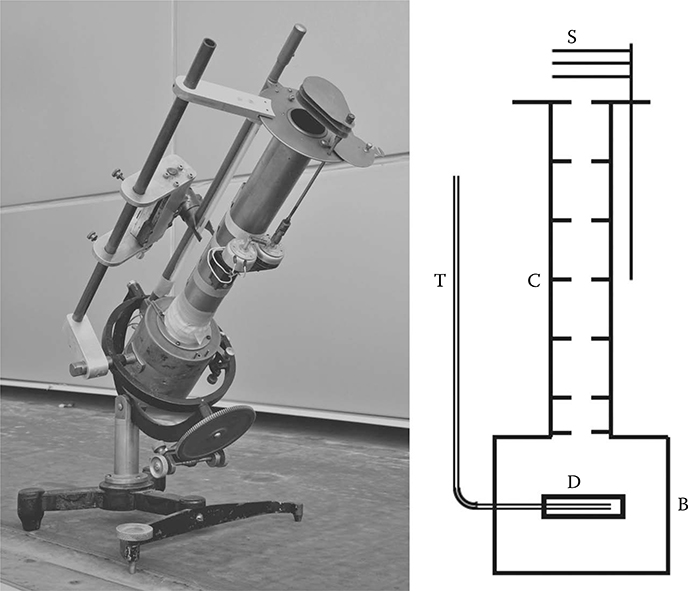
FIGURE 3.5 Design elements of the Abbot silver-disk pyrheliometer used for measuring direct normal irradiance: Thermometer (T) measures the disk (D) temperature located in the base (B) of the instrument separated by a collimating tube (C) defining the field of view that can be shuttered (S) from the direct normal irradiance.
Operation of the instrument required properly aligning the receiver disk with the sun, alternately shading and unshading the receiver, accurately keeping time to 1/5th second, and reading the thermometer to a few hundredths of a degree Celsius. Summarizing the procedure originally specified by Abbot (1911), it is apparent the instrument design was best suited for measurements under very clear and stable atmospheric conditions:
Time (seconds) | Operator Action |
|---|---|
0 | Align instrument with the sun, open instrument cover, close shutter |
80 | Read thermometer |
180 | Read thermometer, open shutter, check alignment |
200 | Read thermometer |
300 | Read thermometer, close shutter |
320 | Read thermometer |
420 | Read thermometer, open shutter |
Note: Continue the readings in above order as desired.
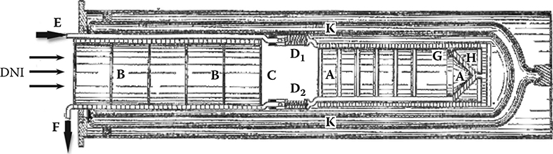
FIGURE 3.6 Smithsonian water-flow pyrheliometer measures direct normal irradiance (DNI) by monitoring the temperature rise of water between points D1 and D2. Abbot’s design introduced the concepts of cavity enhancement for absorbing solar radiation and electrical power substitution used in modern pyrheliometers. (After Abbot, C. G., The Sun and the Welfare of Man, Smithsonian Series, 2, 1929.)
Determining the direct normal irradiance required the correction of all temperature readings for air, stem, and bulb temperatures and multiplying the corrected temperature differences by a calibration constant for the particular instrument used for the measurements. The calibration constant was obtained by direct comparison with the Smithsonian water-flow pyrheliometer traceable to the Smithsonian 1913 Scale of Radiation.
The importance of the silver-disk pyrheliometer to the accurate measurement of solar radiation continued for several decades. As late as 1952, the World Meteorological Organization recommended the instrument for measuring direct normal irradiance.*
3.4.2 SMITHSONIAN WATER-FLOW PYRHELIOMETER (1910)
Also developed by C. G. Abbot at the Smithsonian Institution, this absolute pyrheliometer was based on the measurement principles of calorimetry. As shown in Figure 3.6, the water-flow pyrheliometer measures DNI entering tube (BB), passing through a precision aperture (C), and absorbed by a blackened chamber (AA) with a cone at the base of the chamber to enhance absorption of the radiation. The hollow cylinder (K) insulates the receiving chamber from changes in ambient air temperature. A spiral watercourse encloses the receiving chamber. Distilled water at constant temperature is supplied to an inlet tube (E) where the water enters the chamber wall at a constant rate and passes through a spiral ivory piece (D1) and exits by a similar ivory spiral (D2). A measured length of “hair-like” platinum wire is threaded through each of the ivory spiral channels such that the water bathes the platinum wires, forcing them to the temperature of the water entering and exiting the instrument. When the instrument is exposed to DNI, the resulting temperature difference measured at D1 and D2 and the known aperture area are used to compute solar irradiance. To confirm the water-flow temperature measurements, a coil of wire (H) is used to electrically heat the receiving chamber with a measured current. These electrical substitution measurements were used to confirm the equivalence of solar and electrical power performance of the instrument. Abbot’s design incorporated key features in use today by the pyrheliometers defining the World Radiometric Reference: (1) cavity enhancement of the receiver to increase photon absorption, (2) insulating “muffler” to limit heat exchange between the internal receiver and exterior surfaces of the instrument, and (3) electrical substitution by means of a wire-wound heater at the receiver for comparing measurements of solar-induced heating with a known amount of electrical heating. Although the instrument did not become widely used, it was the basis for the Smithsonian 1913 Scale of Radiation for solar radiation measurements (Abbot and Aldrich, 1932). The instrument’s function as the American absolute reference ended in 1956 with the adoption of the International Pyrheliometric Scale (IPS 1956) that resolved the differences with the Ångström scale of 1905 (Fröhlich, 1991).
* Meeting of the Subcommission on Actinometry, Brussels, 1952.
3.4.3 MARVIN PYRHELIOMETER (1910)
Prior to serving as chief of the U.S. Weather Bureau from 1913 to 1934, C. F. Marvin was developing improved instruments for measuring bright sunshine duration and a pyrheliometer for measuring direct normal solar irradiance. Similar in many respects to the Abbot silver-disk pyrheliometer, the Marvin pyrheliometer used a resistance wire instead of a mercury-in-glass thermometer for measuring the temperature of the blackened silver-disk receiver (Foote, 1918). An electrically operated shutter mounted in front of the collimating tube aperture provided for automated shade and exposure of the receiver to solar radiation. Due to its simpler operation, the Marvin pyrheliometer replaced the Ångström pyrheliometer in 1914 as the instrument used by the U.S. Weather Bureau (Covert, 1925).
3.4.4 ÅNGSTRÖM PYRANOMETER (1919)
Anders Knutsson Ångström, Swedish physicist and meteorologist and son of Knut Ångström, used his father’s principle of electrical compensation developed for the Ångström pyrheliometer as the basis for his pyranometer nearly two decades later. As shown in the schematic diagram in Figure 3.7, the Ångström pyranometer detector consisted of two white strips and two black strips mounted on an insulating framework at the end of a nickel-plated cylinder. A glass hemisphere was mounted to a metal disk to protect the detector from the weather. Thermojunctions were attached to the backs of the strips in good thermal contact and electrically isolated. The operation of the pyranometer was based on maintaining the temperature of the white strips by supplying a measured electrical heating to match the amount of radiant energy absorbed by the black strips (Coulson, 1975). In spite of some attractive design attributes, the Ångström pyranometer was never put into widespread use.
3.4.5 KIPP & ZONEN SOLARIMETER (1924)
A significant advance in the practical measurement of solar radiation is attributed to Dr. W. J. H. Moll, who, as a physics professor at the University of Utrecht, designed the Moll thermopile (Moll, 1923). His design, depicted in Figure 3.8, addressed the measurement performance characteristics still sought in modern pyranometers and pyrheliometers:

FIGURE 3.7 Schematic diagram of the Ångström electrical compensation pyranometer with white thermopile strips (A), black thermopile strips (B), glass hemisphere (G) mounted in a supporting disk (D), desiccant chamber (C), adjusting screws (S), and spirit level (L), (After Coulson, K. L., Solar and Terrestrial Radiation, Methods and Measurements, Academic Press, New York, 1975.)
High level of responsivity (detector output signal produced per unit of incident solar irradiance)
Rapid response to changes in solar irradiance (instrument time constant)
Linearity over the range of expected levels of solar irradiance (consistent responsivity)
Uniform response to radiation within the solar spectrum (generally 0.3 to 3.0 μm)
Minimum influence of ambient temperature on the detector output
In 1924, the Moll thermopile was used by Dr. Ladislas Gorczynski, director of the Polish Meteorological Institute, as the basis for both a pyrheliometer and pyranometer. The resulting Moll–Gorczynski pyranometer was presented to Kipp & Zonen, a scientific instrument company in Delft, the Netherlands, and by 1927, the company was offering “Solarimeters and Pyrheliometers” in their sales catalog.* The handmade Moll thermopiles continued to serve as the basis of Kipp & Zonen radiometers until 1989 when the designs for models CM 1, CM 3, CM 5, and CM 6B were based on electroplated polyamide foil thermopiles.
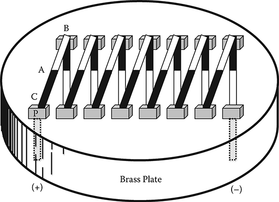
FIGURE 3.8 Concept of the Moll thermopile using thermojunctions of thin (0.005 mm) blackened strips of Manganin and constantan joined at A and soldered at points B and C to copper posts P. The mounting posts are fastened to a thick brass plate about 2 cm in diameter and coated with lacquer to provide electrical isolation and good thermal conductivity for the active junctions.
3.4.6 ROBITZSCH BIMETALLIC ACTINOGRAPH (1932)
Based on a simple thermo-mechanical design, this portable and self-contained recording pyranometer was popular for monitoring solar radiation at remote locations and contributed to the measured data used for estimating the world distribution of global horizontal irradiation (Löf, Duffie, and Smith, 1966). Since its introduction in 1932, the instrument design has been refined and remains commercially available today. Designed by Max Robitzsch (1887–1952), a German meteorologist and professor at the Meteorological Observatory at Lindenberg, the instrument uses a blackened bimetallic strip about 8.5 x 1.5 cm mounted under a protective glass dome about 10 cm in diameter. The differing thermal expansion properties of the materials used to form the bimetallic strip create a simple bimetallic thermometer that responds proportionally to changes in solar irradiance. Using an ink pen and a mechanical linkage attached to the free end of the bimetallic strip, the Robitzsch design records the receiver deflections on chart paper wrapped on a clock-driven drum. The drum rotation can be made in 24 hours or in seven days to produce records of daily irradiation. The bimetallic receiver, mechanical linkage, and recording drum were housed in a weather-resistant metal case (Figure 3.9). Prior to the 1970s, the measurement uncertainties introduced by a variety of undesirable response characteristics resulted in daily total irradiation within ± 10% of the best performing instruments (Coulson, 1975). More recent design improvements have addressed these shortcomings:
* A brief history of Kipp & Zonen is available from http://www.kippzonen.com.

FIGURE 3.9 The Robitzsch bimetallic actinograph was a popular instrument for measuring daily amounts of solar irradiance from about 1932 to 1970 at meteorological stations around the world.
Calibration of the rectangular receiver varied greatly with solar azimuth and elevation.
Pen zero-point depended on the varying thermal exchanges with the day/ night longwave atmospheric conditions; receiver deflections varied with ambient temperature.
Time response was relatively slow at about 15 minutes due to the large thermal mass of the receiver.
There were optical distortions caused by the glass dome.
3.4.7 EPPLEY 180O PYRHELIOMETER (1930)
To address the needs of agriculture and to advance the meteorological observing capabilities in the United States in the early 1920s, the Weather Bureau and the National Bureau of Standards developed a new instrument for measuring total hemispheric solar irradiance on a horizontal surface (Kimball and Hobbs, 1923). Marvin suggested the black and white annular ring concept for the thermopile detector used in the “180° pyrheliometer” design as shown in Figure 3.10. Eppley Laboratory, Inc. introduced the first pyranometer based on the Weather Bureau thermopile at a meeting of the American Meteorological Society in May 1930 and continued to produce the radiometer with improvements for more than 30 years (Coulson, 1975). The National Weather Service (formerly the U.S. Weather Bureau) used variants of this pyranometer from 1951 to 1975 in their SOLRAD network (NREL, 1992).
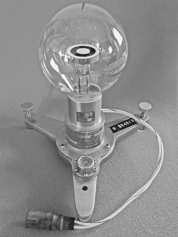
FIGURE 3.10 Eppley Laboratory, Inc., model 50 “light bulb” pyranometer used from 1951 to 1975 by the National Weather Service in their SOLRAD network of 61 stations. (Courtesy of Eppley Laboratory, Inc.)
The thermopile detector consisted of gold-palladium and platinum-rhodium alloys with 10 (early model) or 50 (later model) thermojunctions in good thermal contact but electrically insulated from the concentric rings of the annular design. Measuring about 29 mm in diameter, the detector was made from two thin silver rings and a small inside disk. The outer ring and the small disk were coated with magnesium oxide, a material with high reflectance in the solar spectrum. Depending on the year of manufacture, the inner ring was coated with either lamp black or Parson’s optical black lacquer to provide for low reflectance at solar wavelengths (SOLMET, 1979). The glass bulb was about 76 mm in diameter, made of soda-lime glass about 0.6 mm thick, and filled with dry air at atmospheric pressure at the time of assembly (Coulson, 1975). This glass envelope was the basis for the more common reference to this pyranometer as the Eppley light bulb. Instrument performance was affected by the degradation of the soda-lime glass transmittance, the degradation of black detector paint’s absorptivity with exposure, the lack of detector temperature compensation (except for later models), and the optical distortions associated with the blown-glass envelope. The Parson’s optical black lacquer’s absorptivity deteriorated significantly under exposure to sunlight, turning from black to gray to green. The last production version of this pyranometer was named model 50 to reflect the number of thermojunctions in the detector. In response to the energy crisis of the 1970s, considerable effort was applied to rehabilitating the historical measurement records based on this pyranometer at the National Climatic Data Center to reduce the effects of these instrument performance characteristics on data uncertainty (SOLMET, 1978). The resulting data archive provides the original measured value with additional corresponding “Engineering Correction” data that account for known instrumentation deficiencies:
Calibration changes
Solar radiation measurement scale differences
Midscale chart recorder setting
Pyranometer detector paint degradation
Calibration “cross-match problem” due to the uses of Parson’s black and lamp black paints among the network instruments and calibration references
Temperature response characteristics
In total, the amount of adjustment to these hourly solar irradiance data could exceed 20%, depending on the pyranometers and chart recorders deployed over time at a SOLMET station.
3.4.8 EPPLEY MODEL PSP (1957)
The first model of the precision spectral pyranometer (PSP) developed by the Eppley Laboratory, Inc. was introduced in 1957 (Marchgraber and Drummond, 1960). The PSP has been widely accepted for deployment on land, sea, and aircraft platforms (Figure 3.11). The advanced design improvements of the PSP at the time it was introduced included •
Electrical compensation of the detector response to ambient temperature changes between –20°C and +40°C
Precision optics protecting a smaller thermopile detector than previously used in black-and-white designs resulting in better angular response (±1% over incidence angles of 0° to 80°)

FIGURE 3.11 Eppley Laboratory, Inc., model precision spectral pyranometer. (Courtesy of Eppley Laboratory, Inc.)
A single Parson’s optical black painted receiver to eliminate spectral reflectance and durability issues associated with the white magnesium oxide coating previously used in black-and-white designs
Improved heat transfer characteristics of the detector, domes, and instrument body
Faster time response for measuring rapid changes of irradiance (1 sec for 1/e)
Rugged design for improved long-term operation
Replaceable desiccant for maintaining dry air within the body
Replaceable outer hemispheres for optional color filter measurements of spectral bands
The wire-wound copper–constantan thermopile produces about 10 μvolts per Wm–2 and is mounted under two precision-ground Schott glass hemispheres as shown in Figure 3.12. The double-dome design addresses the need to minimize the convective heat losses between the thermopile and the surrounding environment. The white sunshade protects the instrument’s cast bronze body from thermal gradients caused by solar heating. An optional ventilator is available for providing forced air over the outer hemisphere to reduce the effects of dew, snow, dust, and other potential contaminants from accumulating on the outer dome, hence improving the irradiance measurements (Figure 3.13).
3.4.9 YANISHEVSKY PYRANOMETER (1957)
The Yanishevsky (now Yanishevsky-Savinov) series of pyranometers served as the principal instrument for solar irradiance measurements in the former Soviet Union and continues that tradition in Russia and Central Asia today. The thermopile-type detector used in early models was constructed in a square checkerboard pattern of alternate black and white squares and rectangles (Figure 3.14). Later models have a radial pattern of alternate black and white segments. The latest version, Yanishevsky-Savinov M115-M, pyranometer detector has alternating black and white squares forming a planar detector surface. The thermocouples are composed of alternating strips of Manganin and constantan. The hot junctions are blackened with carbon soot, and cold junctions are whitened with magnesium oxide. A single glass hemisphere protects the black-and-white receiver. Early models also had an auxiliary opaque metal hemisphere for providing a measurement of zero offsets. The measurement performance of the M115-M has been compared with other pyranometers deployed as part of the International Polar Year (Ivanov et al., 2008). Results of the 24-day comparison of hourly irradiances measured by the Norwegian Polar Institute’s reference CMP 11 pyranometer show agreement within accepted measurement uncertainty limits at 6.3 ±5.6 Wm–2 over a measurement range of 0 to 500 Wm–2 (Ivanov, 2008).

FIGURE 3.12 (a) Wire-wound F3 thermopile developed by the Eppley Laboratory, Inc., for use in their model precision spectral pyranometer. (b) Final assembly of Eppley F3 thermopile ready for installation in a model PSP. (Courtesy of Eppley Laboratory, Inc.)

FIGURE 3.13 Two model PSPs installed in Eppley ventilators to reduce effects of outer hemisphere contamination by dew, frost, snow, dust, and other sources. PSP with clear WG295 outer dome in foreground and PSP with RG780 outer dome in background. (Courtesy of Eppley Laboratory, Inc.)
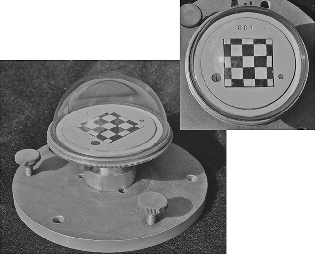
FIGURE 3.14 The Yanishevsky pyranometer served the needs of the former Soviet Union for solar irradiance measurements. The black-and-white thermopile detector measures 3 cm x 3 cm.
3.4.10 EPPLEY MODEL NIP (1957)
The normal incidence pyrheliometer (NIP) designed and manufactured by the Eppley Laboratory, Inc. measures the direct normal (“beam”) solar irradiance. As shown in Figure 3.15, the blackened wire-wound copper–constantan thermopile receiver is at the base of a view-limiting tube providing the 1 to 10 aperture-opening-to-tube-length geometry responsible for the NIP’s 5.7° field of view. In 1956, consistent with the existing solar tracker alignment capabilities and the need to provide instrument design standards, the International Radiation Commission established pyrheliometer design recommendations that included this viewing geometry (Bolle, 2008). Over the years, the double-walled tube has been constructed with an outer wall made of chrome-plated brass, white-painted brass, or stainless steel with the inner wall made of brass and fitted with light-baffle diaphragms to limit stray light from reaching the thermopile receiver. The viewing end of the tube is fitted with a quartz window of 1 mm thickness (currently Infrasil II material). The sealed double-walled construction is filled with dry air at atmospheric pressure at the time of manufacture. This design improves measurement stability, especially during windy conditions. The pyrheliometer has two flanges. The rear flange has three holes previously used for mounting on older solar trackers. The front flange has a sighting diopter arrangement for alignment with the target on the rear flange (Figure 3.16).

FIGURE 3.15 (a) Eppley Laboratory, Inc., model normal incidence pyrheliometer mounted on an automatic solar tracker for measuring direct normal irradiance. (Courtesy of Eppley Laboratory, Inc.) (b) NIP design elements shown in cross section.
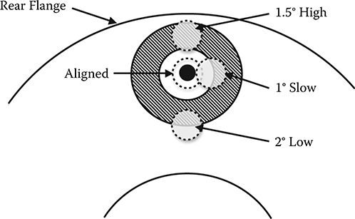
FIGURE 3.16 Diopter target used on the rear flange of a NIP to determine alignment with solar disc. The detector is fully illuminated when the sun spot image is fully within the white area of the target.
Recommended as one of the instruments for use during the 1957–1958 International Geophysical Year (IGY), the NIP continues to be produced today with these performance characteristics: • •
Sensitivity: approx. 8 μvolts/Wm–2
Impedance: approx. 200 ohms
Temperature dependence: ±1% over ambient temperature range –20 to +40°C (Compensation can be supplied over other temperature ranges)
Linearity: ±0.5% from 0 to 1400 Wm–2
Response time: 1 second (1/e signal)
Mechanical vibration: tested up to 20 g’s without damage
Calibration: referenced to Eppley primary standard group of pyrheliometers
Size: 11 inches long
Weight: 5 pounds
3.4.11 EPPLEY MODEL FIR (1968)
The Eppley model precision infrared radiometer (PIR), is designed to measure atmospheric or terrestrial infrared radiation over the wavelength range of 3.4 μm to 50 μm. This pyrgeometer is similar in construction to the model PSP with a single black wire-wound copper–constantan thermopile receiver mounted in a cast bronze body that serves as the cold junction. A protective dome surrounds the thermopile hot junctions and selectively transmits the infrared radiation to the receiver (Figure 3.17). A temperature compensation circuit nominally adjusts the thermopile output for changes in ambient temperature between –20°C and +40°C (other temperature compensation ranges are available). Early models of the PIR used a dome made of thallium bromide-iodide (KRS–5) that was replaced in the 1980s with a silicon hemisphere coated with tellurium and zinc selenide to improve thermal conductance and wavelength response of the instrument. As described in more detail in Chapter 10, the PIR receiver responds to these sources of infrared radiation:
Incoming atmospheric or terrestrial (depending on mounting orientation)
Effective instrument case temperature
Effective hemispheric dome temperature
Therefore, the PIR design includes thermistors in contact with the hemispherical “solar blind” filter and the pyrgeometer case to provide temperature data coincident with the thermopile voltage generated during irradiance measurements. The irradiance can be computed from the calibration coefficients determined for the thermopile, case emittance, and dome correction factor (see Chapter 10). Historically, these calibration coefficients have been primarily determined from measurements made with laboratory blackbody calibrators. Since 2003, pyrgeometer calibrations are traceable to the interim World Infrared Standard Group (WISG) developed by the World Radiation Center (WRC; Grobner and Los, 2007). The WISG is a group of pyrgeometers that form a reference standard that includes two Eppley PIRs.
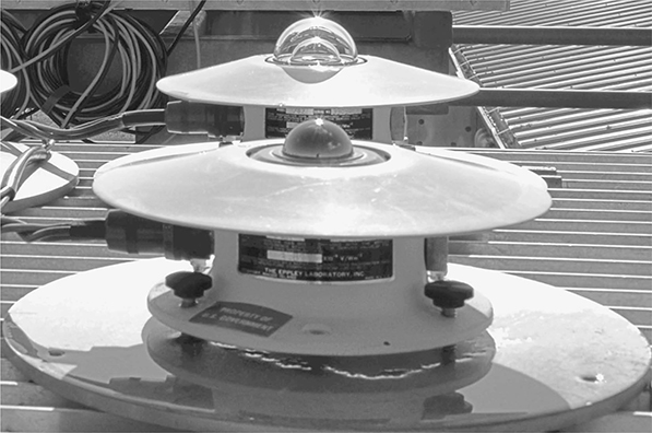
FIGURE 3.17 Eppley Laboratory, Inc., model precision infrared radiometer used for total hemispheric longwave radiation measurements (foreground) with model PSP (background). (Courtesy of Eppley Laboratory, Inc.)
3.4.12 PRIMARY ABSOLUTE CAVITY RADIOMETER (PACRAD) (1969)
This radiometer is historically significant for several reasons. Developed at the Jet Propulsion Laboratory to support NASA’s Deep Space Network Energy Program, the PACRAD was needed to improve the measurement of simulated solar output in space chambers. Nearing retirement, J. M. Kendall, Sr. was tasked with designing a new radiometer after the thermal control system of at least one space probe did not function as predicted by space simulator testing. The simulator design problem was linked to the inability to accurately measure the simulated solar flux in the space chamber. The resulting JPL standard total-radiation absolute radiometer designed by Kendall was used to measure the absolute total radiation intensity with an absolute accuracy of 0.5% and to experimentally determine the Stefan-Boltzmann constant to within 0.5% of the theoretical value (Kendall, 1968). About this time, the scientific community was in need of an absolute solar irradiance measurement reference. A series of pyrheliometer measurement comparisons had produced solar irradiance measurement differences approaching 5% among the Ångström Scale of 1905, the Smithsonian Scale of 1913, and the International Pyrheliometric Scale of 1956 (Latimer, 1973). Clearly, an improved international reference for solar radiation measurement was needed.
Working from first principles of measurement, Kendall applied several new design concepts to develop the PACRAD instrument (Figure 3.18). First, he introduced the cavity-shaped receptor to enhance the detector absorptivity. Earlier pyrheliometer designs used flat plate detectors (i.e, disks or rectangular plates) that were prone to reflecting photons regardless of surface coating and collimator design. Second, the PACRAD had a built-in electrical calibrating heater to provide cavity heating accurately and equivalent to radiation heating. As a result, PACRAD irradiance measurements were based on the ability to make accurate and traceable electrical power measurements (i.e, voltage and resistance) and accurate dimensional measurements (i.e., aperture area) to produce solar irradiance data in Wm–2. A third critical element in Kendall’s design was the attention to heat transfer within the instrument. The materials selection, component design and placement, including the compensation cavity, were based on the need to absorb the incoming solar radiation that is converted to heating of the cavity receiver. The heat flows through a metallic thermal resistor to the massive heat sink to produce a temperature difference of a fraction of a Kelvin. The temperature difference is measured by a thermopile that is electrically calibrated as part of the measurement procedure. Key to the PACRAD design and operation was the thorough characterization of the effects of the various types of heat transfer within the radiometer and the resulting correction factors for all heat transfers that are not equivalent to the heating of the cavity by electrical substitution.
Three models of the PACRAD were built and compared with Eppley Ångström pyrheliometers (Kendall, 1969). Solar measurements taken at Table Mountain, California, on April 23, 1969, with the three PACRAD models agreed with one another within 0.11% and the Ångström pyrheliometers agreed with each other within 0.18%. However, solar irradiance measurements from the pyrheliometers were 2.3% lower than the PACRADs. This discrepancy was later resolved with the establishment of the World Radiometric Reference (WRR) based on a series of International Pyrheliometer Comparisons (IPCs) conducted by the World Radiation Center in Davos, Switzerland.

FIGURE 3.18 The primary absolute cavity radiometer became the basis for the electrically self-calibrating absolute cavity radiometers used to define the World Radiometric Reference. (After Kendall, J.M., Primary Absolute Cavity Radiometer, Technical Report 32–1396, Pasadena, CA, 1969.)
During IPC-III in 1970, Kendall’s third model, PACRAD III, was observed to be very stable and was the only absolute cavity radiometer in the comparison. By 1975, five other absolute cavity designs had been developed and participated in IPC-IV (Fröhlich, 1991; Zerlaut, 1989):
Active cavity radiometer (ACR) by R. C. Willson (Willson, 1973)
Eppley-Kendall PACRAD-type (EPAC) by the Eppley Laboratory, Inc. and J. Kendall (Drummond and Hickey, 1968)
Model PMO developed by the Physikalisch-Meteorologisches Observatorium
Model PVS by Yu. A. Skliarov at the Saratov University in the former Soviet Union
Model TMI, PACRAD-type, by Technical Measurements, Inc.
Because of its performance in IPC-III, the PACRAD III was chosen as the reference instrument for IPC-IV. The weighted average of all instruments for all observations during IPC-IV was 1.0017 with a standard error of only 0.18% among the absolute cavity instruments (Zerlaut, 1989). The subsequent establishment of the absolute WRR measurement scale is a result of the excellent agreement among all of the absolute cavity instruments at IPC-IV and later comparisons. In 1979, based on the results of IPC-IV, WMO adopted the WRR as the replacement for the International Pyrheliometric Scale of 1956 for the measurement of direct normal irradiance. Thus, the PACRAD instrument served an important role in establishing the WRR and providing for more accurate and consistent solar irradiance measurements around the world.*
3.4.13 EPPLEY MODEL 8–48 (1969)
Developed as a lower-cost replacement for the 180° pyrheliometer or Eppley light bulb pyranometer described earlier, this instrument offered improved measurement performance characteristics with a more robust design than its predecessor. In place of a rather large and delicate glass envelope surrounding the detector, a precision-ground optical Schott glass WG295 hemisphere protects the black-and-white segments of the differential thermopile detector from the elements (Figure 3.19). The black (hot) junctions were originally painted with Parson’s optical black and the white (cold) junctions coated with barium sulfate. The relatively large receiver produced about 10 μvolts per Wm–2 and a time response of 5 seconds for a change in signal of 1/e. The challenge of constructing a planar receiver from black and white segments resulted in angular response specifications of ±2% for incidence angles 0–70° and ±5% for incidence angles 70–80°. The balanced black-and-white receiver design, however, results in minimal thermal offset on the order of one Wm–2 (Dutton et al., 2001) and negates the need for a protective sunshade over the body and an inner dome to limit the convective heat losses to the surroundings. In the course of production, these pyranometers have had bodies made from machined aluminum (early years) and painted cast aluminum (current production). A temperature compensation circuit nominally adjusts the thermopile output for changes in ambient temperature between –20°C and +40°C (other temperature compensation ranges are available).
* During this same period, other researchers were developing advanced pyrheliometer designs for solar irradiance measurements from space. A summary of the results from Willson’s active cavity radiometer, NASA’s eclectic satellite pyrheliometer, and others is available from R. C. Willson (1993).
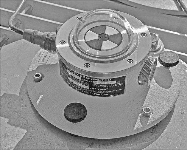
FIGURE 3.19 Eppley Laboratory, Inc., model 8–48 pyranometer exhibits minimal thermal offset due to equal exposure of thermopile junctions to the effective sky temperature. (Courtesy of Eppley Laboratory, Inc.)
3.4.14 LI-COR MODEL LI-200SA (1971)
The origin of this now ubiquitous pyranometer was based on the need for a low-cost radiometer to support the work of the Department of Soil and Water Sciences at the University of Wisconsin (Kerr, Thurtell, and Tanner, 1967). The silicon photodiode detector used in the original design was mounted below a plastic diffuser to provide adequate angular response and coupled with a purpose-built solid-state integrator for recording daily sums of global irradiance. The prototype radiometer was deployed in a 17-station mesoscale network in Wisconsin to study the temporal and spatial variations of solar radiation for applications in bioclimatology (Kerr, Thurtell, and Tanner, 1968). Lambda Instruments Corporation produced the first commercial version of the design in 1971. The name was changed to LI-COR, Inc. in 1978.
As shown in Figure 3.20, the LI-200SA pyranometer is compact (2.38 cm diameter x 2.54 cm tall) and lightweight (28 g). Because the detector is based on the photoelectric effect rather than the thermoelectric effect used for thermopile radiometers, the LI-200SA has a very fast time response (10 µsec). The silicon photodiode, however, does not respond uniformly to all wavelengths and does not respond at all to wavelengths greater than about 1100 nm (Figure 3.20). This limited spectral response increases the measurement uncertainty when compared with thermopile-based detectors (King and Myers, 1997).

FIGURE 3.20 (Upper) LI-COR, Inc. model LI-200SA photodiode-based pyranometer and (Lower) the instrument’s solar spectral response between 350 nm and 1100 nm compared with the spectra for extraterrestrial, sea level, and black-body radiation corresponding to a temperature of 5900 K. (From LI-COR Environmental, Inc. Used by permission.)
3.4.15 ROTATING SHADOWBAND RADIOMETER (1975)
Using a single LI-COR LI-200 pyranometer to measure global and diffuse solar irradiance for computing the coincident direct irradiance was the design basis for the DIAL radiometer (Wesely, 1982). The original DIAL radiometer prototype got its name from two aspects of the instrument design (Figure 3.21). When viewed from the axis of rotation, the shade assembly resembles the face of a dial with a revolving position indicator formed by the shade band. Also, the instrument name could be derived from its abilities to measure diffuse (D), estimate direct (I), and measure global (AL) solar irradiance components. The design innovations addressed the needs for a low-cost radiometer system that would be simple to install, operate, and maintain for purposes of estimating the broadband solar irradiances at the earth’s surface and the corresponding atmospheric turbidity. The innovations included the following:

FIGURE 3.21 The DIAL radiometer used a rotating shade (resembling a dial) to alternately shade and unshade a fast-response pyranometer to measure diffuse (D) and global (AL) irradiances for estimating the corresponding incident (I) direct normal irradiance component. (After Wesley, M. L., Journal of Applied Meteorology, 21, 1982.)
No mechanical adjustment to the shading device
Compact and lightweight mounting arrangement
Commercially available pyranometer using a silicon photodiode mounted beneath a cosine-correction diffuser
Integrated assembly, suitable for field applications in remote areas
The DIAL radiometer concept was later commercialized for applications in solar resource assessment and atmospheric science. Commercial versions based on the DIAL radiometer concept are now known as a rotating shadowband radiometer (RSR), a rotating shadowband pyranometer (RSP), a thermopile shadowband radiometer (TSR), or a multifilter rotating shadowband radiometer (MFRSR). The DIAL radiometer design used a small pyranometer positioned under a motorized shading band that completed one rotation about every 4 minutes. The band was ∼0 .9 cm wide and ∼6.0 cm away from the 0.8 cm diameter diffuser on the pyranometer. With a shadowband rotation speed of about 0.25 rpm, the pyranometer detector was shaded for about 0.7 s. This was a sufficient shading interval for strip-chart recorders of the day to respond and display the minimum signal from the fast-response photodiode detector used in the pyranometer. The diffuse and global irradiance data were based on the minimum (shaded) and maximum (unshaded) pyranometer signals, respectively.
Initial comparisons of vertically integrated estimates of atmospheric turbidity made with a DIAL radiometer and two broadband thermopile pyranometers (Eppley Laboratory, Inc. model 8–48—unshaded and shaded) suggested single reading accuracy of ±30% for turbidity measurements for solar zenith angles less than 65°. When data from the DIAL radiometer were corrected for angular response and excessive shading of diffuse sky radiance due to shade bandwidth, averaged results compared within ±2%. This comparison missed the spectral response problem seen on clear days with modern rotating shadow band radiometers.
Since the introduction of the rotating shadowband concept, considerable effort has been made to characterize and improve the system design and data correction algorithms (Augustyn et al., 2004; Harrison, Michalsky, and Berndt, 1994; King and Myers, 1997; Rosenthal and Roberg, 1994; Stoffel, Riordan, and Bigger, 1991; Vignola, 2006). Specifically, these response characteristics of an RSR continue to be studied:
Spectral response: From the outset of DIAL radiometer design, the need to provide fast response to changing irradiance levels has been met by the use of a pyranometer with a silicon photodiode detector. The time response for such a detector is on the order of 10 μsec compared with 1 to 5 seconds (or longer) for thermal detectors. Because the photodiode detector responds nonuniformly to the solar radiation between about 300 nm and 1100 nm, various correction schemes have been developed to simulate the corresponding broadband measurements. Because a silicon photodiode is less responsive near the 400 nm spectral region (i.e., blue), so-called spectral mismatch errors of up to 30% can occur for measurements of clear-sky diffuse irradiance. The advent of small thermopile detectors has provided the opportunity for fast-acting and broadband spectral response when used in an RSR (http://www.nrel.gov/midc/SRRL_TSR/).
Temperature response: The electrical current produced by the photoelectric effect in a photodiode detector increases with increasing temperature. Corrections to the measured solar irradiance have been made with coincident measurements of air temperature near the RSR and from detector temperature measurements from a thermistor placed near the photodiode detector RSR irradiance measurement uncertainties due to temperature response can be on the order of 3% for a 10°C temperature change (King and Myers, 1997).
Angular response: Computing accurate direct normal irradiance from RSR measurements of global and diffuse components requires adequate design and characterization of the pyranometer for angular or “cosine” response. Typically, commercially available pyranometers have adequate angular response characteristics between incidence angles of 0° and 60° as measured normal to the detector surface. Pyranometer angular response is commonly undefined for incidence angles greater than 85°. Accounting for the specific angular response characteristics of a pyranometer can reduce the measurement uncertainty of direct normal irradiance as estimated from RSR measurements by a few percent for solar zenith angles less than about 70°.
Coming full circle, the original intent of the DIAL radiometer design has been fulfilled by the MFRSR with its capabilities to measure solar spectral irradiance at selected wavelengths allowing for the retrieval of atmospheric optical depths of aerosols, water vapor, and ozone (Harrison et al., 1994). The MFRSR uses six independent interference filter-silicon photodiode combinations, mounted in a temperature-controlled enclosure, to detect spectral irradiance using six narrowband filters (10 nm wide). One unfiltered channel is used to obtain broadband solar irradiance estimates (Figure 3.22). As a result, the MFRSR design provides for the spectral measurement of diffuse and global irradiance and estimates of direct normal irradiance.
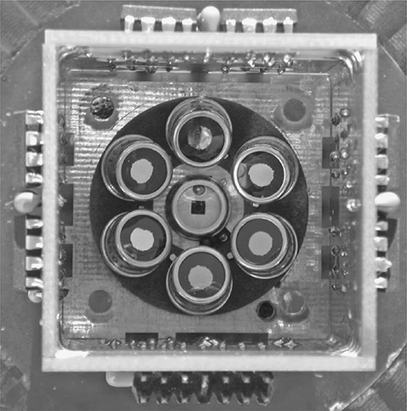
FIGURE 3.22 Multifilter rotating shadowband radiometer detector arrangement as positioned beneath the diffuser.
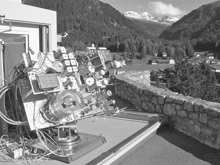
FIGURE 3.23 (See color insert.) The WRR is determined by a group of absolute cavity radiometers named the World Standard Group. At the moment, the WSG is composed of six instruments: PMO–2, PMO-5, CROM-2L, PACRAD-III, TMI-67814, and HF-18748.
3.4.16 WORLD STANDARD GROUP (1979)
The Physikalisch-Meteorologisches Observatorium Davos (PMOD) established the World Radiation Center (WRC) to guarantee international homogeneity of solar radiation measurements by maintaining the World Standard Group (WSG) of electrically self-calibrating absolute cavity radiometers. The WSG defines the World Radiometric Reference (WRR) as a detector-based measurement reference (Fröhlich, 1978). Presently, the WSG comprises six well-characterized instruments: PMO-2, PMO-5, CROM-2L, PACRAD-III, TMI–67814, AND HF–18748 (Figure 3.23). The WSG serves as the reference measurements for the IPC held every five years at the WRC.
3.5 Recent Advances in Solar Measurements
3.5.1 AUTOMATIC HICKEY-FRIEDEN CAVITY RADIOMETER
The Eppley Laboratory, Inc. model automatic Hickey–Frieden (AHF) absolute cavity pyrheliometer is the automated version of the model HF radiometer that first participated in an IPC in 1980 (Zerlaut, 1989). Similar to the PACRAD and in collaboration with JPL, the HF cavity radiometer was developed to serve as a reference standard for the measurement of DNI. In fact, HF-18748 is one of the WSG absolute cavity radiometers defining the WRR at the WRC in Davos, Switzerland.
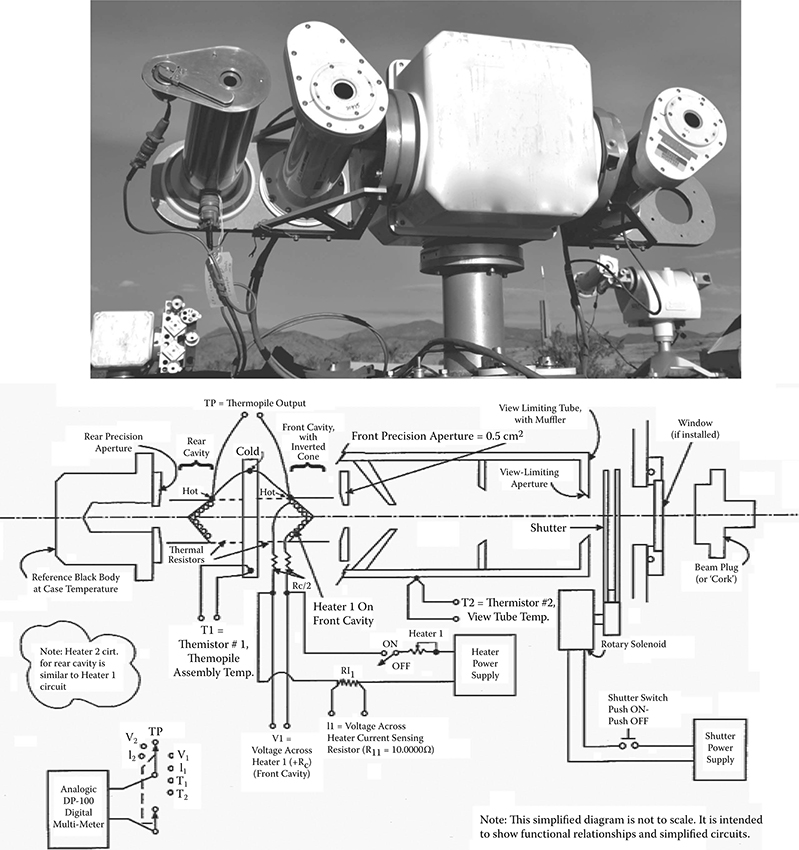
FIGURE 3.24 Eppley Laboratory, Inc., model automatic Hickey–Frieden electrically self-calibrating absolute cavity radiometer. (Top: Courtesy of Eppley Laboratory, Inc.; bottom: after Reda, I., NREL Report No. TP-463-20619, 1996.)
An electrically self-calibrating instrument, the sensor consists of a balanced cavity receiver pair attached to a circular wire-wound and plated thermopile (Figure 3.24). The blackened cavity receivers are fitted with heater windings that allow for absolute operation using the electrical substitution method, which relates radiant power to electrical power in SI units. The forward cavity views the DNI through a precision aperture immediately in front of the cavity receiver and behind a view-limiting aperture. The precision aperture is made of Invar, an alloy of 63.8% iron, 36% nickel, and 0.2% carbon with a very low coefficient of thermal expansion. The area is nominally 50 mm2 and is measured for each unit. The rear receiver views an ambient temperature black body. The HF radiometer element with a baffled view-limiting tube and black body are fitted into an outer tube that acts as the enclosure for the instrument and reduces thermal gradients in the instrument due to wind and rapid changes to ambient temperature. The model AHF has an automatic shutter attached to the outer tube for simplifying the self-calibration and measurement controls.
The operation of the cavity radiometer and the measurements of the required calibration parameters are performed using digital electronics (AHF and later versions of the HF). The control functions include setting of the calibration heater power level, activation of the calibration heater, selection of the signals to be measured, and control of the digital multimeter measurement functions and ranges. The measured parameters include the thermopile signal, the heater voltage, and the heater current that is measured as the voltage drop across a 10-ohm precision resistor. The instrument temperature may also be measured using an internally mounted thermistor. The digital multimeter resolution of 100 nanovolts allows for the measurement of a thermopile signal change equivalent in radiation to approximately 0.1 Wm–2.
Although these are absolute devices, the radiometers are compared with the Eppley reference cavity radiometers that have participated in multiple IPCs and other intercomparisons to provide direct calibration traceability to the WRR.
3.5.2 TOTAL IRRADIANCE MONITOR (TIM)
The Laboratory for Atmospheric and Space Physics at the University of Colorado at Boulder designed, built, and operates the solar total irradiance monitor (TIM) as one of the instruments developed for NASA as part of the SOlar Radiation and Climate Experiment (SORCE) launched in January 2003 (Kopp, Lawrence, and Rottman, 2003). The instrument continues the 25-year record of space-based measurements of total solar irradiance (TSI) that began in 1979 with the earth radiation budget (ERB) instrument and continues with the active cavity radiometer irradiance monitor (ACRIM) and variability of solar irradiance and gravity oscillations (VIRGO) radiometers. With an estimated absolute accuracy of 350 ppm (0.035%), the TIM can detect relative changes in solar irradiance to less than 10 ppm/yr (0.001%/yr), allowing determination of possible long-term variations in solar output. The TIM has four electrical substitution cavity radiometers (ESRs) to provide for measurement redundancy and for monitoring sensor degradation via duty cycling. The cavity interiors are etched nickel phosphorus (NiP) producing solar reflectances in the range of 10–4. Each ESR can be independently shuttered from sunlight. The electrical power needed to maintain fixed cavity temperature during shutter cycles determines the radiative power absorbed by the cavity due to the entering solar power. The ESRs are balanced as pairs, one acting as a thermal reference while the other is actively driven to the temperature of the corresponding reference cavity. The use of phase-sensitive detection provides for the high measurement precision of the instrument (Gundlach, Adelberger, Heckel, and Swanson, 1996).
Comparing TSI measurements during 2008 from the TIM (∼1361 Wm–2) coincident with those from ACRIM III (∼1363 Wm–2) and VIRGO (∼1366 Wm–2) suggests a negative bias of about 5 Wm–2 for the TIM (http://www.pmodwrc.ch/pmod.php?topic=tsi/composite/SolarConstant). The TSI measurements resulted in a workshop hosted by NIST and NASA in 2005 to discuss instrument design, measurement uncertainties, and stabilities in detail (Butler, Johnson, Rice, Shirley, and Barnes, 2008). Notable among the findings was the relative placement of the view-limiting and precision apertures relative to the cavity receiver in the instrument designs (see Figure 3.25). The TIM positions the smaller precision aperture at the front of the instrument so that only the light that is intended for measurement enters the cavity. All other cavity radiometers place the view-limiting aperture at the front, allowing excess light into the instrument interior that can lead to erroneously high irradiance measurements from scattered light.
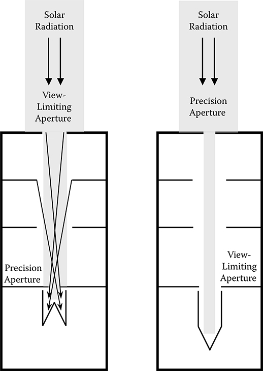
FIGURE 3.25 The relative position of the view-limiting and precision apertures is different between the designs of absolute cavity radiometers (left) and the total irradiance monitor. The optical layout of the TIM (right) places the small precision aperture at the front of the instrument so that only the solar radiation to be measured enters the cavity detector (left). With the precision aperture near the cavity detector, excess radiation is allowed into the instrument interior that can lead to erroneously high irradiance measurements from scatter (indicated by the arrows). (After Kopp, G., and J. L. Lean, Geophys. Res. Letters Frontier article, 38, 2011.)
The TIM value of total solar irradiance is 1360.8 ± 0.5 Wm–2 during the 2008 solar minimum period (Kopp and Lean, 2011). The discrepancy between the canonical minimum value of TSI of 1365.4 ±1.3 Wm–2 and the TIM value remains under investigation.
3.5.3 PMOD MODEL 8 (PM08)
During 2009–2010, the PMOD developed a new prototype model in its series of model PMO cavity radiometers. The PMO8 design goals were to improve the performance of the existing model PMO6 by reducing or eliminating these measurement issues:
Static nonequivalence
Temperature dependency
Dynamic nonequivalence
Aperture heating
Like the PMO6 production unit, the PMO8 prototype is an electrically self-calibrating absolute cavity pyrheliometer designed to accurately substitute radiant power with electrical power for measuring DNI. During operation of the instrument, an electronic circuit maintains a constant heat flux from the cavity heater by adjusting the input electrical power. The heat flux is measured differentially between the receiving cavity and the reference cavity to compensate for the rate of change of the heat sink’s temperature.
In comparison, the standard mode of PMO6 operation consists of alternate measurements of cavity heating with the shutter closed and open. The duration of each shutter cycle (closed and open) is selectable with a default value of 60 seconds. The operator determines the number of cycles and the integration time. The start time of the measurements can be set to a predefined time. After every open–closed cycle the irradiance is shown on the display and sent out to the RS232 port for recording.
The new PMO8 prototype features the following:
Synchronous shutter control
Two heater power levels
Continuous sampling (50 ms)
Serial communications via RS232 or USB interface
Results of the PMO8 participation in IPC-XI in 2010 will be used to verify the design and determine the readiness for production.
Summary
The measurement of radiant energy remains a difficult and challenging science in spite of the fact that fundamental radiometry has a long history of steady improvements. Beginning with the need to satisfy basic curiosities of physicists and astronomers, the present interests in solar energy conversion and global climate change continue to motivate the development of more accurate, reliable, and economical radiometers for ground- and satellite-based observations. The current internationally accepted measurement reference for solar irradiance, the WRR, is a detector-based standard with an estimated measurement uncertainty of ±0.3% and a precision of ±0.1%. Improvement of the WRR appears imminent as scientific and engineering advances are applied to the measurement of solar energy.
Questions
Who is credited with developing the first pyrheliometer for measuring direct normal irradiance?
What thermopile design facilitated the development of the modern pyranometer?
When was the World Radiometric Reference established as the international measurement standard for solar irradiance?
What is the currently accepted value of the total solar irradiance?
Name the response characteristic contributing most to the estimated measurement uncertainty of a photodiode-based pyranometer.
Name the type of radiometer designed to measure atmospheric or terrestrial infrared radiation over the wavelength range of 3.4 to 50 μm.
In what year did the U.S. Weather Bureau begin the routine measurement of solar radiation using a pyranometer?
References
Abbot, C. G. 1911. The silver disk pyrheliometer. Smithsonian Miscellaneous Collection 56:7.
Abbot, C. G. 1929. The sun and the welfare of man. In the Smithsonian Series Volume 2, ed. Charles Greenley Abbot. New York: The Series Publishers, Inc.
Abbot, C. G. and L. B. Aldrich. 1916. The pyranometer—an instrument for measuring sky radiation. Smithsonian Miscellaneous Collection 66(7).
Abbot, C. G. and L. B. Aldrich. 1932. An improved water-flow pyrheliometer and the standard scale of solar radiation. Smithsonian Miscellaneous Collection 3182(87):8.
Ångström, K. 1893. Eine elegtrische Kompensationsmethode zur quantitativen Bestmmung strahlender Warme. Nova Acta Regiae Societatis Scientiarum Upsala 3(16) (Translated in Physical Review 1, 1894).
Ångström, K. 1899. The absolute determination of the radiation of heat with the electric compensation pyrheliometer, with examples of the application of this instrument. Astrophysical Journal 9:332–346.
Augustyn, J., T. Geer, T. Stoffel, R. Kessler, E. Kern, R. Little, F. Vignola, and B. Boyson. 2004. Update of algorithm to correct direct normal irradiance measurements made with a rotating shadow band pyranometer. In Proceedings of Solar-2004, American Solar Energy Society, Portland, Oregon, July 10–14.
Beaubien, D. J., A. Bisberg, and A. F. Beaubien. 1998. Investigations in pyranometer design. Journal of Atmospheric and Oceanic Technology 15:677–686.
Bolle, Hans-Jürgen, 2008. International Radiation Commissions 1896 to 2008: Research into atmospheric radiation from IMO to IAMAS. International Association of Meteorology and Atmospheric Sciences, IAMAS Publication Series No. 1, ISBN 978–3–00–024666–1. Available at: http://www.irc-iamas.org/resources/
Butler, J., B. C. Johnson, J. P. Rice, E. L. Shirley, and R. A. Barnes. 2008. Sources of differences in on-orbital total solar irradiance measurements and description of a proposed laboratory intercomparison. Journal of Research of the National Institute of Standards and Technology 113:187–203.
Callendar, H. L. and A. Fowler. 1906. The horizontal bolometer. Proceedings of the Royal Society Series A. 77:15–16.
Coulson, K. L. 1975. Solar and terrestrial radiation: Methods and measurements. New York: Academic Press.
Covert, R. N. 1925. Meteorological instruments and apparatus employed in the U.S. Weather Bureau. J. Opt. Soc. Amer. Rev. Sci. Inst. 10:299–425.
Crova, M. A. 1876. New pyrheliometer. American Journal of Science and Arts Volume XI, Third Series (January–June), eds. J. D. Dana, B. Silliman, and E. S. Dana, 220–221. New Haven: Editors.
Dorno, C. 1923. Progress in radiation measurements. Monthly Weather Review 50(10). U.S. Weather Bureau.
Drummond, A. J. 1970. A survey of the important developments in thermal radiometry. In A. J. Drummond, ed., Advances in geophysics (Vol. 14). New York: Academic Press.
Drummond, A. J. and J. R. Hickey. 1968. The Eppley-JPL Solar Constant Measurement Program. Solar Energy 12:217–232.
Drummond, A. J., W. J. Scholes, J. J. H. Brown, and R. E. Nelson. 1968. Radiation including Satellite Techniques. Proceedings of the WMO/IUGG Symposium held in Bergen, August 1968. WMO No. 248, 549 pp.
Dutton, E. G., J. J. Michalsky, T. Stoffel, B. W. Forgan, J. Hickey, D. W. Nelson, T. L. Alberta, and I. Reda. 2001. Measurement of broadband diffuse solar irradiance using current commercial instrumentation with a correction for thermal offset errors. Journal of Atmospheric and Oceanic Technology 18:297–314.
Eddy, J. A. 1976. The Maunder Minimum. Science 192:1189–1202. DOI: 10.1126/science.192.4245.1189
Foote, P. D. 1918. Some characteristics of the Marvin pyrheliometer. Scientific Papers of the Bureau of Standards, No. 323. Department of Commerce. Issued June 28, 1918 (Government Printing Office).
Fröhlich, C. 1991. History of solar radiometry and the world radiometric reference. Metrologia 28:111–115.
Glickman, T. S. (ed.). 2000. Glossary of meteorology, 2d ed. American Meteorological Society. Available at: http://amsglossary.allenpress.com/glossary
Gröbner J. and A. Los. 2007. Laboratory calibration of pyrgeometers with known spectral responsivities. Applied Optics 46:7419–7425.
Gundlach, J. H., E. G. Adelberger, B. R. Heckel, and H. E. Swanson. 1996. New technique for measuring Newton’s constant G. Phys. Rev. D 54:R1256–R1259.
Hand, I. F. 1941. A summary of total solar and sky radiation measurements in the United States. Monthly Weather Review 69:95–125.
Harrison, L. and J. Michalsky. 1994. Objective algorithms for the retrieval of optical depths from ground-based measurements. Applied Optics 33:5126–5132.
Harrison, L., J. Michalsky, and J. Berndt. 1994. Automated multifilter rotating shadow-band radiometer: An instrument for optical depth and radiation measurements. Applied Optics 33:5118–5125.
Iqbal, M. 1983. An introduction to solar radiation. New York: Academic Press.
Ivanov, B., P. Svyaschennikov, J.-B. Orbaek, C.-P. Nillsen, N. Ivanov, V. Timachev, A. Semenov, and S. Kaschin. 2008. Intercomparison and analysis of radiation data obtained by Russian and Norwegian standard radiation sensors on example of Barentsburg and Ny-Ålesund research stations. Journal of the CNR’s Network of Polar Research Polarnet Technical Report, Scientific and Technical Report Series, ISSN 1592–5064. Roberto Azzolini (ed.).
Jensenius Jr., J. S. and G. M. Carter. 1979. Specialized agricultural weather guidance for South Carolina. TDL Office Note 79–15, Silver Spring, MD: National Weather Service, National Oceanic and Atmospheric Administration, U.S. Department of Commerce.
Jensenius Jr., J. S. and G. F. Cotton. 1981. The development and testing of automated solar energy forecasts based on the model output statistics (MOS) technique. In Proceedings of the first workshop on terrestrial solar resource forecasting and on the use of satellites for terrestrial solar resource assessment, Newark, DE, Boulder, CO: American Solar Energy Society, pp 22–29.
Kendall, J. M. 1968. The JPL standard total-radiation absolute radiometer. Technical Report 32–1263, Jet Propulsion Laboratory, Pasadena, CA, May 15, 1968.
Kendall, J. M. 1969. Primary absolute cavity radiometer. Technical Report 32–1396, Jet Propulsion Laboratory, Pasadena, CA, July 15, 1969.
Kerr, J. P., G. W. Thurtell, and C. B. Tanner. 1967. An integrating pyranometer for climatological observer stations and mesoscale networks. Journal of Applied Meteorology 6:688–694.
Kerr, J. P., G. W. Thurtell, and C. B. Tanner. 1968. Mesoscale sampling of global radiation analysis of data from Wisconsin. Monthly Weather Review 96:237–241.
Kimball, H. H. and H. E. Hobbs. 1923. A new form of thermoelectric recording pyrheliometer. Monthly Weather Review 51:239–242.
King, D. L. and D. R. Myers. 1997. Silicon-photodiode pyranometers: Operational characteristics, historical experiences, and new calibration procedures. Paper presented at the 26th IEEE Photovoltaic Specialists Conference, September 29–October 3, Anaheim, CA
Kopp, G., G. Lawrence, and G. Rottman. 2003. The total irradiance monitor design and on-orbit functionality. In SPIE Proc. 5171–5174, 2003, pp. 14–25.
Kopp, G. and J. L. Lean. 2011. A new, lower value of total solar irradiance: Evidence and climate significance. Geophys. Res. Letters Frontier article 38: L01706. DOI: 10.1029/2010GL045777.
Latimer, J. R. 1973. On the Ångström and Smithsonian absolute pyrheliometric scales and the International Pyrheliometric Scale 1956. Tellus 25:586–592.
Löf, G. O. G., J. A. Duffie, and C. O. Smith. 1966. World distribution of solar radiation. Solar Energy 10:27–37.
Marchgraber, R. M. and A. J. Drummond. 1960. A precision radiometer for the measurement of total radiation in selected spectral bands. Monograph No. 4, 10–12, Paris: Int. Union Geodesy Geophys.
Marty, C., R. Philipona, J. Delamere, E. G. Dutton, J. Michalsky, K. Stamnes, R. Storvold, T. Stoffel, S. A. Clough, and E. J. Mlawer. 2003. Downward longwave irradiance uncertainty under arctic atmospheres: Measurements and modeling. J. Geophys. Res. 108. DOI: 10.1029/2002JD002937
Michalsky, J., E. G. Dutton, D. Nelson, J. Wendell, S. Wilcox, A. Andreas, P. Gotseff, D. Myers, I. Reda, T. Stoffel, K. Behrens, T. Carlund, W. Finsterle, and D. Halliwell. 2011. An extensive comparison of commercial pyrheliometers under a wide range of routine observing conditions. Journal of Atmospheric and Oceanic Technology 28:752–766.
Michalsky, J. J., R. Perez, R. Stewart, B. A. LeBaron, and L. Harrison. 1988. Design and development of a rotating shadowband radiometer solar radiation/daylight network. Solar Energy 41:577–581.
Moll, W. J. H. 1923. A theromopile for measuring radiation. Proc. Phys. Soc. London Sect. B 35:257–260.
National Renewable Energy Laboratory (NREL). 1992. User’s manual—1961–1990 National Solar Radiation Data Base, Version 1.0. NSRDB—Volume 1. NREL/TP-463-4859, National Renewable Energy Laboratory, 243 pp. Also available as TD-3282, National Climatic Data Center, Asheville, NC.
Reda, I. 1996. Calibration of a solar absolute cavity radiometer with traceability to the world radiometric reference. NREL Report No. TP-463-20619, 79 pp.
Rosenthal, A. L. and J. M. Roberg. 1994. Twelve month performance evaluation for the rotating shadowband radiometer. Contractor Report, Sandia National Laboratories, SAND94–1248.
SOLMET. 1978. User’s manual—hourly solar radiation—surface meteorological observations, Vol. 1, TD-9724 Asheville, NC: National Climatic Data Center.
SOLMET. 1979. Final report—hourly solar radiation—surface meteorological observations, Vol. 2, TD-9724. Asheville, NC: National Climatic Data Center.
Stoffel, T., C. Riordan, and J. Bigger. 1991. Joint EPRI/SERI Project to evaluate solar radiation measurement systems for electric utility solar radiation resource assessment, The conference record of the twenty-second IEEE photovoltaic specialists conference, 2992, 533.
Vignola, F. 2006. Removing systematic errors from rotating shadowband pyranometer data. In Proceedings of the 35th ASES annual conference, Denver, CO.
Waldmeier, M. 1961. The sunspot-activity in the years 1612–1960. Zurich: Schulthess.
Wesely, M. L. 1982. Simplified techniques to study components of solar radiation under haze and clouds. Journal of Applied Meteorology 21:373–383.
Willson, R. C. 1973. Active cavity radiometer. Applied Optics 12:810–817.
Willson, R. C. 1993. Solar irradiance. In R. J. Gurney, J. L. Foster, and C. L. Parkinson, eds., Atlas of satellite observations related to global change. New York: Cambridge University Press.
World Meteorological Organization (WMO). 1965. Measurement of radiation and sunshine. Guide to Meteorological Instrument and Observing Practices, 2d ed, WMO No. 8, TP3
World Meteorological Organization (WMO). 2008. Measurement of radiation and sunshine. Guide to Meteorological Instruments and Observing Practices, 7th ed., WMO-No. 8, Available at: http://www.wmo.int/pages/prog/www/IMOP/IMOP-home.xhtml
Zerlaut, G. 1989. Solar radiation instrumentation. In R.L. Hulstrom, ed., Solar resources. Cambridge, MA: MIT Press.