
8 Measuring Solar Radiation on a Tilted Surface
The real question now at issue is simply the variability of daily or quite frequent observed values of solar intensity...
Charles F. Marvin
(1858–1943)
8.1 Introduction
When evaluating the performance of a solar energy conversion system, it is necessary to know the irradiance incident on the collector. The incident solar irradiance either can be estimated from the direct normal irradiance (DNI) and diffuse horizontal irradiance (DHI) values, or the incident irradiance can be measured. For concentrating solar power systems (CSP) the DNI is the only irradiance measurement or model estimate needed to represent the energy input to the collector. The global tilted irradiance (GTI) is needed for nonconcentrating (flat plate) solar collectors. GTI is the incident irradiance on a surface with a given tilt and azimuth orientation. Surfaces of interest can vary from building façades facing north to flat rooftops to any collector tilt and orientation in between.
When specifying collector tilts and orientations, the notation used in this book will be GTI (Tilt, Orientation), where Tilt is given in degrees from the horizontal, and Orientation is in degrees measured eastward from true north (0°). For example, total irradiance on a surface tilted up 30° from a horizontal surface and facing true south (180°) is designated GTI(30°,180°).
It is impractical to assess the solar resource by measuring solar irradiance on a surface at every possible tilt and orientation. Therefore, models have been developed that use measured or estimated DNI and DHI components to calculate an approximation for tilted surface GTI. A tilted surface will receive irradiance reflected from the ground and will receive reflected irradiance from nearby objects that are within its field of view. The ground-reflected irradiance is often difficult to calculate because the reflectance is not spatially uniform and the absorption and reflectance properties of the surface change the spectral composition of the reflected irradiance from that of the incident solar spectral distribution. For a specularly reflecting surface, the angle of reflectance is equal to the angle of incidence. However, natural surfaces are generally granular in character, so an approximation is used to estimate the ground-reflected irradiance. A generic formula is often used to calculate GTI is
where szaT is the angle of incidence of the DNI with respect to the tilted surface, T is the tilt angle of the surface from the horizontal, and p is the average albedo or reflectivity of the ground near the tilted surface. While the DNI can be measured with considerable accuracy and szaT can be calculated precisely (Equation 2.7), the other two terms in the equation are approximations (see Appendix A for further discussions on modeling GTI). Therefore, to know the solar radiation incident on a tilted solar collector with any precision, the GTI must be measured with a pyranometer.
Pyranometers were originally designed for the measurement of global horizontal irradiance (GHI) and installed on horizontal surfaces. It is only with the need to measure the performance of solar energy systems that measurements on other than horizontal surfaces were considered and pyranometers were increasingly used on tilted surfaces. When tilted, the measurement performance of the pyranometer changes. The nature and magnitude of the change depend on the design of the pyranometer. The change in behavior of three types of pyranometers will be discussed:
Secondary reference and other single black detector thermopile pyranometers
Black-and-white pyranometers
Photodiode pyranometers
8.2 Effect of Tilt on Single Black Detector Pyranometers
In single black detector thermopile pyranometers the conduction of heat from the black detector through the thermopile to the body of the pyranometer is measured to determine the radiant energy (solar irradiance) incident on the instrument. Extraneous heat flow by conduction, convection, and radiative transfer systematically reduces heat flow through the thermopile and, hence, affects the measurements. Each pyranometer model has its own design features to minimize other conductive losses as well as convective and radiative losses within the pyranometer. Thermal isolation and insulation help reduce the conductive losses, and the use of double domes over the black detector help to reduce the convective thermal losses. Still, there are some losses due to conduction, radiation, and convection in these pyranometers.
Tilting a pyranometer from the horizontal affects the convective losses and radiative losses (thermal offsets) of thermopile pyranometers. For single black thermopile pyranometers the conductive losses remain about the same as when they are used horizontally since orientation typically does not affect conduction. The convective losses change because the heat flow patterns within the domes change. Thermal offsets actually decrease as the pyranometer is tilted at a steeper angle because the pyranometer sees more of the warmer ground and less of the colder sky. Figure 8.1 shows the thermal offsets from Eppley precision spectral pyranometers (PSPs) at different tilts (Vignola, Long, and Reda, 2007). As the pyranometer tilt increases, the observed thermal offsets decrease. The pyranometers facing the ground (i.e., inverted) show almost no thermal offset. Of course, the amount of radiative loss depends on the difference between the target temperature (e.g., the sky dome temperature) and ambient temperature (instrument temperature) as discussed in Chapter 5. Many factors influence sky temperature—primarily cloud cover and precipitable water vapor. Sky temperature can vary over time scales of seconds and minutes with underlying seasonal trends. Therefore, pyranometers with minimal thermal offset losses are better suited for tilted measurements.
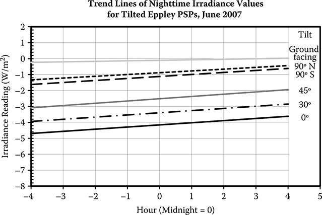
FIGURE 8.1 Trend lines of nighttime values for tilted PSPs for June 2007. Note that as the pyranometer’s tilt increases, the nighttime values get smaller. This means that the infrared loss becomes less as the pyranometer “sees” more of the ground.
Tests of the effect of tilt on pyranometer performance are typically performed indoors under controlled conditions and, consequently, do not show thermal offset effects. For single black detector thermopile instruments, the change in responsivity with tilt is minimal (on the order of ±1% to ±2%). It is presumed that these changes are related to changes in convective losses, but the exact nature of the change and the magnitude vary with pyranometer model. Some pyranometers show a slight responsivity increase with tilt, while others may have a slight decrease.
While there are accurate measurements of tilt effects indoors, outdoor evaluations of tilt effects are very difficult because of the variation in ground reflection on the instrument and the absence of an absolute pyranometer to provide a reference measurement. In addition, the reduction of thermal offsets as the pyranometer is tilted and the imperfect Lambertian response of the pyranometer further complicate the analysis. Typical uncertainties quoted for the tilt effect vary from 0.5% for secondary-standard instruments and up to 2% for some first-class instruments (Hulstrom, 1989). While these values were determined indoors and provide an estimate of the uncertainties, they may not be as accurate under actual field operating conditions. Note that the uncertainty caused by tilting a pyranometer must be added in quadrature to the uncertainty determined for the pyranometer when it is installed horizontally. Therefore, tilted measurements from a given pyranometer will always have a larger uncertainty than GHI measurements from the same instrument.
8.3 Effect of Tilt on Black-and-White Pyranometers
The effect of tilt on black-and-white pyranometers is greater than on single black detector thermopile pyranometers. It is postulated that convective losses are responsible for most of the effects of tilt on pyranometer responsivity (Hulstrom, 1989). Therefore, one might expect that black-and-white pyranometers, with only a single dome, are more affected by tilt, and this is indeed the case.
In the lab, the pyranometer performance is measured using a light source that is perpendicular to the pyranometer, and the whole platform is tilted at various angles; the black-and-white pyranometer shows greater tilt effects than the single black detector pyranometer.
The deviation of a black-and-white pyranometer response at tilt compared with a horizontal pyranometer varies from about 3% (Wardle and McKay, 1984; Wardle, Dahlgren, Dehne, Liedquist, McArthur, Miyake et al., 1996) to as much as 8% (McArthur, Dahlgren, Dehne, Hämäläinen, Liedquist, Maxwell et al., 1995). It is uncertain how these losses translate to field conditions where convective losses are often larger than experienced in the laboratory as a result of wind blowing across the pyranometer dome and the naturally changing temperatures and relative humidity of the air. The lack of an absolute pyranometer makes evaluation of tilt effects in the field difficult to measure and characterize. Furthermore, it is difficult to isolate tilt effects from other issues in the field. Even the best pyranometers have at least 2% to 3% absolute uncertainty and a nonuniform Lambertian response. In addition, the responsivity of black-and-white pyranometers has an azimuthal dependence as well as an imperfect Lambertian response. Isolating a 2% to 8% tilt effect from the other effects is fraught with uncertainty. The change in responsivity as a function of tilt is shown in Figure 8.2 for a Schenk Star pyranometer.
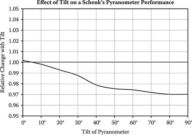
FIGURE 8.2 Relative effect of tilt on a Schenk pyranometer. Data taken indoors. (From Andersson, H.E.B., L. Liedquist, J. Lindblad, and L. A. Norsten, Report SP-PAPP 1981: 7, Statens Provningsanstalt [National Testing Institute], Borås, Sweden, 1981).
The uncertainty resulting from the tilt effect has to be added in quadrature to the typical black-and-white instrument uncertainty of ±5%. Since this can lead to estimated measurement uncertainties of over 9%, it is not considered good practice to use black-and-white pyranometers on tilted surfaces.
8.4 Effect of Tilt on Photodiode Pyranometers
One would not expect photodiode pyranometers to be affected by tilt because they are not thermal instruments. Photodiode pyranometers, in fact, are often used to test the effect of tilt on thermopile pyranometers under controlled laboratory conditions where they can serve as the control. Photodiode pyranometers have a limited spectral response. In the field, the change in spectral composition of reflected light affects the measurement of tilted irradiance by photodiode pyranometers. In general, ground-reflected irradiance, especially from vegetation, is shifted more to the infrared portion of the spectrum. On a 90° tilted surface, the ground-reflected irradiance is roughly equal to one-half the GHI times the reflectivity of the surface (see Equation 8.1). Typical ground reflectivity is approximately 0.2 for non-snow-covered surfaces. Hence, the contribution of the ground-reflected irradiance to a 90° tilted pyranometer is about 10% of the GHI, and for a 45° tilted pyranometer the reflected contribution is only about 3% of the GHI. Therefore, even a 30% change in responsivity resulting from a spectral shift in the irradiance would lead to an increase in uncertainty in the GTI measurement of only about 1% for the 45° tilt case. Of course, the initial absolute uncertainty in the photodiode reading is about 5%. A clear-day comparison of thermopile and photodiode pyranometers is shown in Figure 8.3 for a southern orientation with tilts of 0°, 40°, and 90° and in Figure 8.4 for 90° tilted pyranometers facing north, east, south, and west. Data are taken from the NREL’s Solar Radiation Research Laboratory’s Baseline Measurement System using PSP and LI-200 pyranometers (www.nrel.gov/midc/srrl_bms). The difference between the photodiode and thermopile pyranometers is divided by the thermopile reading to obtain the percent difference. Average nighttime readings were subtracted from the daytime values to reduce the effect of the thermal offset on the values. Differences vary between –5% and +5% for the south-facing pyranometers and 0% to 15% for the 90° tilted pyranometers, depending on the time of day and the tilt and orientation of the instruments. The pattern of difference changes for every orientation. It is difficult to separate cosine response differences from tilt responses from shifts caused by the spectral reflectivity changes throughout the day for these outdoor measurements. Again, the absence of an absolute pyranometer makes it difficult to precisely determine the error caused by the tilt alone.
8.5 Recommendations for Tilted Irradiance Measurements
The accuracy of tilted irradiance measurements will always be less than the accuracy of horizontal measurements because the changes in pyranometer performance caused by tilting must be added to the uncertainty of the performance when the pyranometer is horizontal. Most broadband thermopile pyranometers are subject to almost negligible spectral shifts of ground-reflected irradiance since glass domes used on thermopile instruments block none or only a small portion of the near-infrared irradiance. For the very best measurements on tilted surfaces, single black detector thermopile pyranometers that use double domes made of material that uniformly pass a broad range of wavelengths yield the most accurate broadband measurements of GTI. Single black detector thermopile pyranometers with double domes that pass a slightly narrower band of wavelengths are the second choice. Photodiode pyranometers have no tilt effect, and, if used to evaluate a photovoltaic (PV) panel with a similar spectral response, it might be the best choice for the tilted measurement if the ground-reflected contribution is small (i.e., the tilt is less than 45°).
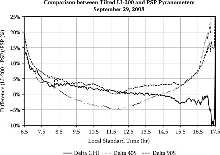
FIGURE 8.3 Clear-day comparison of thermopile Eppley PSP with a LI-COR LI-200 photodiode pyranometer on south-facing surfaces tilted 0°, 40°, and 90°. Solar Radiation Research Laboratory at NREL on September 29, 2008. The thermopile instrument agrees rather well over the day with the photodiode response increasing in the morning and afternoon. At tilts of 40° and 90° the behavior is different with deviations due to cosine response, spectral reflectivity response and tilt response. It is difficult to isolate and quantify the various sources of error.
The specifications and measurement characteristics of the pyranometer on the horizontal surface helps determine the quality of the tilted measurements that the pyranometer could make. Pyranometers that make good GHI measurements have a likelihood of making good GTI measurements. Of course, the shallower the tilt, the less likely there will be a significant tilt effect for any pyranometer. Black-and-white pyranometers have significant tilt effects and are not recommended for use on tilted surfaces.
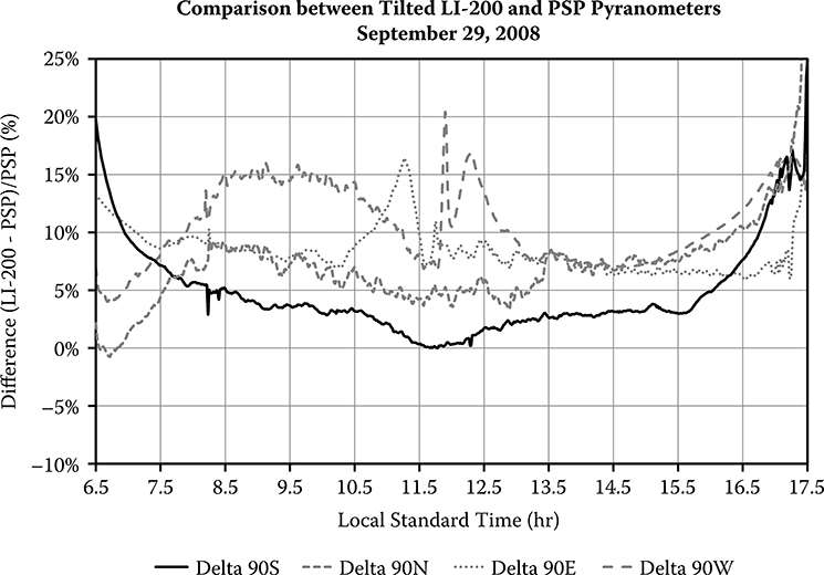
FIGURE 8.4 Clear-day comparison of thermopile Eppley PSP pyranometer with a LI-COR LI-200 photodiode pyranometer on north, east, south, and west surfaces tilted 90°. Data taken at the Solar Radiation Research Laboratory at NREL on September 29, 2008. Differences range from 0 to 15% over the day. The peak differences of the east-and west-facing pyranometers around solar noon is likely the cat ears effect of the LI-200 pyranometer discussed in Chapter 5.
8.6 Notes on Modeling PV System Performance With Data From Photodiode Pyranometers
Photodiode pyranometers have spectral responses similar to silicon-based PV modules, and, consequently, these pyranometers may correlate better with the output of a PV system than a broadband thermopile pyranometer. To model the performance of a photovoltaic system, not only is it necessary to know the total incident solar irradiance on the module, but also the incident solar radiation must be separated into its diffuse and beam components to properly calculate the transmission of the solar radiation through the glazing. The separation of diffuse and beam components presents a special problem for tilted measurements made with photodiode pyranometers because the spectral composition of the beam and diffuse components are significantly different on clear days and the responsivity of the photodiode is different for the beam and diffuse components.
The glazing on the front of a solar module reflects an increasing percentage of the irradiance as the angle of incidence increases (Fresnel reflection) (see Figure 8.5). Notice that the glazing does not exhibit a Lambertian response, which would be uniform with angle of incidence. The difference from a Lambertian response is especially divergent for angles of incidence larger than 50°. DNI values and the glazing’s refractive index (often modified by an antireflective coating) are required for accurate estimates of the transmission through the glazing to the solar cell. PV system performance models are developed and tested with DNI measurements obtained from pyrheliometers and GTI measurements obtained using high-quality pyranometers. The PV system performance models incorporate the effects of changes in the spectral composition incident on the solar cell. This is the reason that there is a better spectral match of the photodiode pyranometer response; however, using photodiode pyranometer data causes the performance model to overcorrect for the changes in spectral composition. This is analogous to counting the effect of changes in the spectral composition twice.
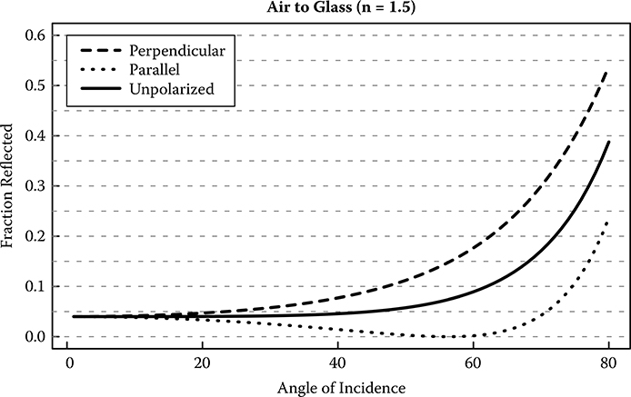
FIGURE 8.5 Generic plot of the reflectivity on incident solar radiation on a sheet of glass. The percentage of reflected light remains fairly constant until the angle of incidence gets to about 45°. To illustrate the potential complexity of the reflection of light from glass, the reflection of polarized light is also shown. Antireflective coatings are used with photovoltaic modules, and these coatings can reduce the reflected light by a factor of two or more. (From Andersson, H.E.B., L. Liedquist, J. Lindblad, and L.A. Norsten, Calibration of Pyranometers, Report SP-PAPP, 1981. With permission.)
The need to separate the DNI contribution from the GTI measurement to properly account for the reflectivity of the glazing further complicates the performance estimates if a photodiode pyranometer is used for GTI measurements. DNI values can be obtained from measurements made with pyrheliometers, estimated from rotating shadowband radiometer (RSR) measurements, or modeled from measured GHI values. As discussed in Chapter 5, photodiode pyranometers systematically underestimate the DHI value on clear days by 20 to 30%, and if a pyrheliometer is used to obtain the DNI value, the diffuse and ground-reflected irradiance reading of the photodiode pyranometer will underestimate contributions of the diffuse component to the total energy incident on the solar cells. If not taken into account, this underestimation of the incident energy can overestimate the efficiency of the solar system.
If the DNI is obtained with an RSR, it is important to thoroughly understand how the DHI and DNI values are obtained and whether responsivities have been corrected for differences in the spectral composition of DNI and DHI irradiance. If the DNI is obtained from a RSR that has been corrected for the underestimation of the diffuse component, the DNI can be treated as if it came from a pyrheliometer, except the uncertainty in the DNI value is increased. If the DHI values have not been spectrally corrected, then an algorithm must be applied to correct for the effects caused by the underreporting of the DHI on clear days.
Correlations between DNI and tilted measurements are crude at best (Vignola, 2003). Therefore, if DNI measurements are not available, GHI measurements are needed to estimate the DNI value required for modeling photovoltaic module performance. Models correlating DNI with GHI are usually derived from GHI measurements made with high-quality pyranometers using single black thermopile detectors. Because each type of pyranometer has its characteristic systematic errors, using correlations derived from one type of pyranometer with measurements made with a different model or type of pyranometer increases the uncertainty in the results and may introduce systematic errors. Therefore, if a photodiode-based pyranometer is used for the GHI measurement, then a DNI-GHI correlation derived using GHI measurements with a photodiode pyranometer should be employed. The same applies to GHI measurements obtained from thermopile-based pyranometers.
Spectral effects from ground-reflected irradiance are similar for a tilted photodiode pyranometer and solar PV cells. So while good correlations with solar module performance can be obtained, the absolute uncertainty in module efficiency is larger than the uncertainty obtained when irradiance measurements are made with thermopile-based pyrheliometers and pyranometers.
Questions
What is the best pyranometer to use for tilted surface measurements?
What type of pyranometer should not be used for tilted measurements?
Why do the design qualities of a photodiode pyranometer both make it good and bad for tilted measurements?
References
Andersson, H. E. B., L. Liedquist, J. Lindblad, and L. A. Norsten. 1981. Calibration of pyranometers. Report SP-PAPP 1981: 7. Statens Provningsanstalt (National Testing Institute), Borås, Sweden.
ASTM Standard E1036–08. 2008. Standard test methods for electrical performance of non-concentrator terrestrial photovoltaic modules and arrays using reference cells. West Conshohocken, PA: ASTM International.
ASTM Standard E948–09. 2009. Standard test method for electrical performance of photovoltaic cells using reference cells under simulated sunlight. West Conshohocken, PA: ASTM International.
ASTM Standard E1362–10. 2010. Standard test method for calibration of non-concentrator photovoltaic secondary reference cells. West Conshohocken, PA: ASTM International.
Flowers, E. C. 1984. Solar radiation measurements. In Proceedings of the recent advances in pyranometry, International Energy Agency IEA Task IX solar radiation and pyranometer studies. Downsview, Ontario, Canada: Atmospheric Environment Service.
Hulstrom, R. L. (ed.). 1989. Solar resources. Cambridge, MA: MIT Press.
International Electrotechnical Commission (IEC). 2007. IEC 60904–2: Photovoltaic devices – Part 2: Requirements for reference solar cells. London: British Standards Institution.
McArthur, L. J. B., L. Dahlgren, K. Dehne, M. Hämäläinen, L. Liedquist, G. Maxwell, C. V. Wells, D. I. Wardle. 1995. Using pyranometers in tests of solar energy converters. International Energy Agency, Solar Heating and Cooling Programme, Task 9, IEA-SNCP–9F1. Downsview, Ontario, Canada: Experimental Studies Division, Atmospheric Environmental Service.
Vignola, F. 2003. Beam-tilted correlations. Paper presented at the solar 2003 American Solar Energy Society Conference, Austin, TX.
Vignola, F., C. N. Long, and I. Reda. 2007. Evaluation of methods to correct for IR loss in Eppley PSP diffuse measurements. Paper presented at the SPIE conference, San Diego, CA.
Wardle, D. I., L. Dahlgren, K. Dehne, L. Liedquist, L. J. B. McArthur, Y. Miyake, O. Motschka, C. A. Velds, and C. V. Wells. 1996. Improved measurements of solar irradiance by means of detailed pyranometer characterisation. International Energy Agency, Solar Heating and Cooling Programme, Task9, IEA-SHCP–9C–2. Downsview, Ontario, Canada: National Atmospheric Radiation Centre, Atmospheric Environmental Service.
Wardle, D. L. and D. C. McKay (eds.). 1984. Recent advances in pyranometery. Paper presented at the symposium proceedings of the Swedish Meteorological and Hydrological Institute, Norrkoping, Sweden.