
7 Rotating Shadowband Radiometers
The total assembly is called the “dial” radiometer both because the rotating shade resembles the face of a dial with a revolving arm and because the device is used to measure “D-and-I-AL” quantities (Diffuse, Incident direct-beam, and globAL irradiance).
Marvin L. Wesely
(1944–2003)
7.1 Introduction
A simple rotating shadowband radiometer was introduced by Wesely (1982), as discussed in Chapter 3; it used a LI-COR LI-200 photodiode pyranometer because a rapid response time (10 μsec for the LI-200) was needed as the shading band passed over the detector to block direct sunlight. The band rotated at constant speed and completely shaded the diffuser every 4 or 5 minutes depending on the motor selected. The output from the pyranometer was a current; therefore, a low-temperature coefficient resistor was used in the circuit to produce a voltage that was output to a chart recorder. An upper envelope of the global horizontal irradiance (GHI) bound the output on a clear day, and a lower envelope represented the diffuse horizontal irradiance (DHI) (Figure. 7.1). Direct normal irradiance (DNI) could be calculated from the difference in the global and diffuse horizontal irradiance after division by the cosine of the solar zenith angle. The labor-intensive process of analyzing the chart manually limited the reduction of these paper charts to useful data.
Michalsky, Berndt, and Schuster (1986) built a microprocessor-controlled version of the rotating shadowband radiometer that recorded four measurements from the photodiode pyranometer for each rotation of the stepper motor-driven band. The measurements are made with the band in the nadir position to measure unobstructed global horizontal irradiance, blocking the sun to measure the diffuse horizontal irradiance, and with the band offset symmetrically slightly before and slightly after the sun-blocking position to estimate the excess diffuse sky radiation blocked by the band during the blocked-sun measurement. The blocked-sun position of the band prevents the direct sun from reaching the receiver but also blocks circumsolar diffuse skylight. An estimate of this correction is calculated using the two side-band measurements.
Yankee Environmental Systems, Inc. (http://www.yesinc.com) manufactures a seven-channel rotating shadowband radiometer (MFR–7) (Figure 7.2). Six of the channels are 10 nm-wide spectral channels in the visible and near infrared (NIR); the seventh channel is a broadband solar sensor. It uses the same band rotation and sampling algorithm as the Michalsky et al. (1986) design.
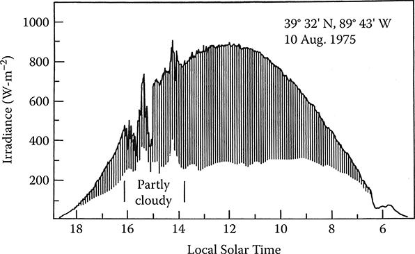
FIGURE 7.1 Chart recorder output from a Wesely-type constant-speed rotating shadow-band radiometer. The bottom of the envelope represents the diffuse horizontal irradiance, and the upper envelope the global horizontal irradiance. The direct can be calculated from these two measurements and is proportional to the length of the vertical lines. (Courtesy of the American Meteorological Society.)
Edward Kern developed a version of the rotating shadowband radiometer that is controlled by a commercial data logger (Figure 7.3). This instrument rotates a band at high speed with simultaneous and rapid sampling of the photodiode pyranometer. The minimum signal is used as the first-order diffuse signal, and measurements just outside this minimum value are used to estimate a shadowband correction for excess circumsolar diffuse sunlight blockage. Its operation is described in the RSR2 Installation and Operation Manual (available at http://www.irradiance.com/rsr.xhtml).
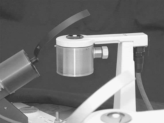
FIGURE 7.2 (See color insert.) The Yankee Environmental Systems, Inc. seven-channel multifilter rotating shadowband radiometer model MFR–7.
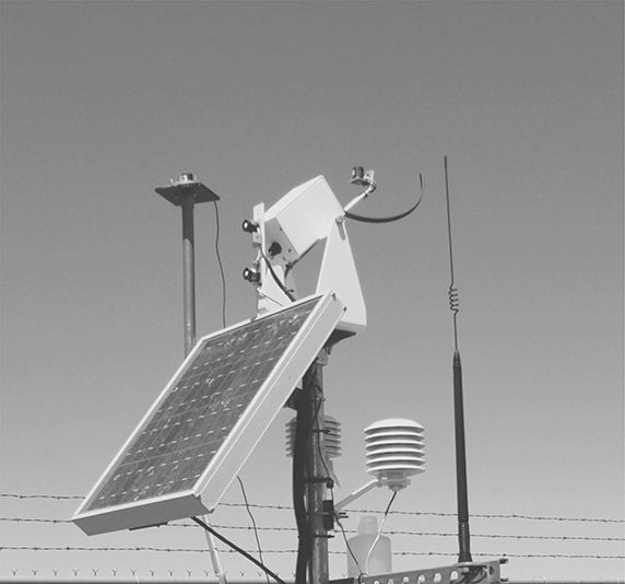
FIGURE 7.3 The Irradiance, Inc. rotating shadowband radiometer version 2 (RSR2). (Courtesy of Ed Kern.)
Recently, Solar Millennium AG has developed a version of the rotating shadow-band radiometer (http://www.solarmillennium.de/technology/meteostations/mode-of-operation/index.xhtml) that appears very similar to Irradiance, Inc.’s instrument. Both companies offer complete installation and data reduction services.
Prede Co. Ltd. of Japan (http://www.prede.com) makes the rotating shadow blade (RSB–100), which is advertised to work with either thermopile or photodiode sensors of any manufacturer. The authors have no experience with this device.
Rotating shadowband radiometers are popular because they provide all three solar components for a much lower cost than do traditional thermopile radiometers that require an expensive tracker to perform the direct normal and diffuse horizontal measurements. To date, their major drawback is that they require several corrections that limit their accuracy compared with the accuracy of thermopile radiometers. When a few percent accuracy matter, as in multimillion-dollar power plants, then a thermopile measurement system is the preferred choice. The next two sections describe the two fundamentally different implementations of the rotating shadowband radiometer.
7.2 Rotating Shadowband Radiometer
This section describes instruments similar to that developed by Kern that uses a commercial photodiode pyranometer, a commercial data-logger system, and a band driven to shade the pyranometer on command. The hardware for the Solar Millennium instrument appears very similar, but nothing is known regarding the corrections applied to it since the correction algorithms are proprietary; however, the basic correction algorithms used for the Irradiance, Inc. RSR data are available in Augustyn et al. (2004).

FIGURE 7.4 The response of the LI-COR, Inc. LI-200 to shading by the RSR2 band.
The need to automatically measure the direct and diffuse irradiance inexpensively led to the development of the RSR, which was originally called the rotating shadowband pyranometer (RSP). As the shadowband arm sweeps past the pyranometer, the data logger goes into a fast data-gathering mode and measures the minimum irradiance during the sweep of the arm (Figure 7.4). This minimum irradiance is the initial estimate of diffuse irradiance. Measurements just before and after shading are used to estimate the diffuse irradiance blocked by the band during the measurements when the solar disk is totally eclipsed. This provides a positive correction that is added to the minimum irradiance for a corrected diffuse horizontal irradiance (DHI) estimate. The average reading taken when the band is far from shading the diffuser is the global irradiance. The difference between the global horizontal irradiance (GHI) and DHI is the direct horizontal irradiance. The direct normal irradiance (DNI) is calculated by dividing the direct horizontal irradiance by the cosine of the incident angle, which is the solar zenith angle for a horizontal pyranometer. (Note that the standard abbreviation for diffuse horizontal irradiance, DHI, should not be confused with the direct horizontal irradiance.)
Direct normal irradiance (DNI) is calculated using
where sza is the solar zenith angle.
In principle, the installation and operation of the RSR is simple and straightforward. The RSR can run unattended in the field for long periods, and the operation of the instrument does not require a complex and, hence, expensive tracker to point the instrument at the sun. The instrument is easy to align and is easily integrated into an automated monitoring station (see Figure 7.3).
Although only one pyranometer is required to obtain the GHI, DHI, and DNI measurements, an auxiliary pyranometer is an option for automated data quality control, and some models integrate an unshaded pyranometer into the design. The National Renewable Energy Laboratory (NREL) has developed a quality control check for an RSR with a primary pyranometer for the GHI, DHI, and DNI measurements and a secondary pyranometer for GHI measurements. If the performance of either pyranometer degrades because of soiling, precipitation, or other problems, then the output ratio between the two pyranometers changes. The auxiliary pyranometer can also be tilted at other angles such as by the station latitude. The tilted pyranometer tends to be less affected by dirt, moisture, frost, or snow, especially if it is tilted at 90°. However, the quality control check becomes less dependable because ground-reflected light has a significant wavelength dependence, as does the photodiode-based pyranometer used in the Irradiance, Inc. RSR. For tilted pyranometers, quality control checks are not reliable for hours during the months when the sun rises and sets behind the tilted pyranometer.
In practice, the accuracy of the RSR is only as good as the pyranometer used, and the uncertainties in the measured DHI and computed DNI are greater than the uncertainties associated with the GHI measurements. There are large statistical errors associated with infrequent sampling and large systematic errors associated with using a photodiode pyranometer, especially for the DHI measurements. To record the DHI when the band sweeps in front of the pyranometer, the pyranometer needs a fast response time. This limits the choice of pyranometers. Thermopile pyranometers are generally better instruments for broadband shortwave measurement because they have a uniform response over most solar wavelengths; however, their response is too slow for shadow-band operation. Consequently, photodiode pyranometers are used in most RSRs.
A random error is introduced by the lower sampling rates of GHI and DHI using the RSR compared with frequent sampling possible with thermopile instruments. Variable cloudiness will increase the scatter of the RSR values for DNI and DHI when compared with pyrheliometers and pyranometers that sample continuously over the measurement period. Newer models of the Irradiance, Inc. RSR take several readings during a minute and initiate more frequent band rotation and sampling during periods of rapidly changing GHI, whereas older models took a single reading, typically every minute. This scatter in the measured data is random, and when averaged over longer periods the two measurements approach the same mean value Figure 7.5. clearly indicates the reduction in scatter when 1-minute data are compared with 15-minute data for the same data set.
A systematic error in some of the original RSRs was the calculation of the cosine of the solar zenith angle. Because of limited memory in the data acquisition and control system, an approximate formula for the solar position was used. This led to uncertainties in the cosine of the solar zenith angle, and these errors are imbedded in the calculated values of DNI (Vignola, 2006).
Systematic errors in the DHI occur because the shadowband obscures more than just the sun when it passes in front of the pyranometer. Samples near the shading minimum are used to correct for the excess sky blockage by the shadowband (Figure 7.4).
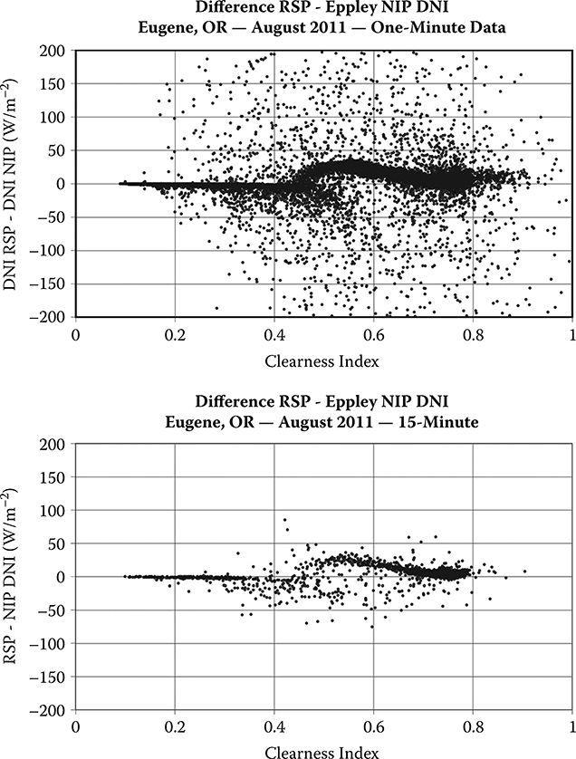
FIGURE 7.5 While there is much scatter caused by the less frequent sampling of the photodiode pyranometer, the mean of the photodiode DNI measurements approaches the thermopile results; note the reduction in scatter with time averaging. Clearly, there are further improvements possible for clearness indices around 0.55.
The photodiode pyranometer has a spectral dependence, and when it is used to measure DHI the responsivity determined for GHI measurements produces DHI values that match the GHI or are lower by as much as 30% depending on whether the sky is completely cloudy or completely clear. Said another way, the DHI responsivity of the photodiode pyranometer is almost 30% less for a clear blue sky than for an overcast sky. The systematic reduction of the DHI for a clear blue sky results in an overestimate of the DNI by about 5% during clear episodes. The deviation from true cosine response and the temperature dependence of the photodiode pyranometer also cause systematic errors. King, Boyson, Hansen, and Bower (1998) characterized many of the systematic errors of the LI-COR Model LI-200 pyranometer that is used in the Irradiance, Inc. RSR instruments. Typical deviations from true cosine response were shown in Figure 5.19. In the RSR, the angular response and temperature corrections to the LI-200 measurements of GHI are based on King et al.’s analysis of these systematic errors. When plotted against time of day, the LI-200’s responsivity takes on a shape similar to a cat’s front profile with peaks occurring near a solar zenith angle of 81° (Augustyn et al., 2002). This cat ears effect (Figure 5.25) is similar for all LI-COR pyranometers and is related to the shape of the diffuser and artificial horizon on the pyranometer. This diffuser produces a good cosine response over most of the range of solar zenith angles but has difficulties producing a precise cosine response at solar zenith angles greater than 75° (as do all pyranometers whether they are photodiode or thermopile based). The GHI corrections in the Irradiance, Inc. RSR include the corrections suggested by King et al. and the cat ears corrections in Augustyn et al. (2004).
Vignola (1999) published a study on the diffuse spectral responsivity of the LI-COR pyranometer. This study showed the magnitude of the deviation and also provided a model of the diffuse responsivity as a function of the clearness index. In 2005, NREL funded a study to see if the results from an RSR with a LI-COR pyranometer could be improved by removing the systematic errors (Vignola, 2006). The RSR was similar to the previous RSR, but a correction algorithm was added to the data-logging program in an attempt to remove the systematic errors that were produced. First the GHI and the DHI values were corrected to eliminate the effects of temperature, and the cat ears corrections helped improve the cosine response. Next, the diffuse spectral responsivity was corrected using an algorithm based on Vignola’s (1999) study but using the corrected GHI values. Finally, a more accurate algorithm was used to calculate the cosine of the solar zenith angle, which was then used to calculate the DNI from the direct horizontal values.
Other improvements in design and operation were introduced at the same time. The sampling frequency has been increased from 1 per minute to as many as 20 per minute. The higher sampling rates should produce more accurate results during rapidly varying atmospheric conditions. Temperature measurements on the pyranometer were also introduced to better determine the temperature correction to the responsivity. Tests show that the corrections to the RSR data improve the accuracy of the measurements significantly. Comparisons between Schenk (black-and-white pyranometer) DHI and DHI measured with RSRs agree to within a few percent over the full range of clearness index (Figure 7.6). Figure 7.6 also indicates the improvement in scatter with averaging time, as was shown for the DNI in Figure 7.5. It is especially evident in Figure 7.5 that there is still room for improvement in the DNI corrections.
Two common measurement artifacts can appear in the RSR data. The first relates to the LI-COR pyranometer. During some mornings, a bead of moisture collects on the diffuser of the pyranometer. This bead directs sunlight striking at low angles onto the photodiode. This slightly increases the GHI but does not affect the DHI as it comes from all parts of the sky. When the DHI is subtracted from the GHI, the slight increase in GHI increases the calculated DNI significantly because early in the morning the cosine of the large solar zenith angle is small, and when dividing this into the direct horizontal value the error is amplified.
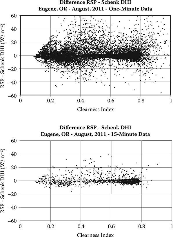
FIGURE 7.6 Comparison of corrected RSR DHI and Schenk black-and-white pyranometer DHI measurements; note the reduction in scatter with time averaging.
Occasionally the band does not rotate when it should, and the DHI value exhibits a sudden spike while the DNI has a sudden dip. This problem is most evident on clear days. In the original RSPs this problem appears to increase as the instrument ages. A software modification has removed this problem from the latest version of the RSR.
There are ongoing efforts to improve the measurements of RSRs. The correction method described in this chapter works for RSR instruments using LI-COR pyranometers. Other instrument manufacturers use their own proprietary algorithms to improve their instrument performance. Of course, corrections removing systematic errors can be applied only to well-maintained instruments with known calibration histories. If corrections are applied to instruments with unknown or poor calibration records or to instruments that are soiled, corrections may actually make the values deviate further from the truth. To address the soiling problem, the development of an automatic cleaning for RSR instruments is under way.
7.3 Multifilter Rotating Shadowband Radiometer
The multifilter version of the rotating shadowband radiometer (MFRSR) was developed in the early 1990s (Harrison, Michalsky, and Berndt, 1994). The instrument retained a broadband silicon channel and added measurements at six additional wavelengths with full widths at half maximum transmission of around 10 nm. Five of the filters are between strong absorption bands and are used to calculate column aerosol optical depths near 415, 500, 615, 673, and 870 nm. One is in the water vapor band centered near 940 nm that can be used to calculate water vapor column. The MFRSR differs from the Irradiance, Inc. RSR in that the rotating shadowband makes three stops on its rotation: one stop just short of shading the sensor, one stop that shades the sensor, and a final stop just after shading the sensor. The extra stops that do not quite block the direct sun on the diffuser allow the diffuse irradiance that is shaded by the large band on the sun-shaded stop to be estimated.
The focus of the next part of this section is on improving the retrievals of global and diffuse horizontal and direct normal irradiance made with the MFRSR’s photodiode detector. Corrections have to be made for the pyranometer’s angular response departures from a perfect cosine response (Lambertian response), for small temperature departures from the nominal set temperature in the MFRSR, and, most significantly, for the spectral dependence of a photodiode’s response.
Before deployment in the field, each MFRSR head is mounted in a laboratory angular response bench so that the center of rotation of the head is on the axis and perpendicular to a nearly collimated beam of a xenon arc lamp located about 5 meters from the MFRSR (Michalsky, Harrison, and Berkheiser, 1995). Measurements are made every 1° from the horizon to the zenith in the north, south, east, and west directions. These measurements are normalized to the zenith measurement producing a cosine response for each of the seven MFRSR channels.
The “raw” measurements from the MFRSR operating outdoors are the uncorrected global horizontal irradiance and the blocked diffuse horizontal irradiance, which is corrected by using the average of the two side-band measurements subtracted from the uncorrected global horizontal to correct for the excess skylight that is blocked during the sun-blocked measurement. This modified diffuse is subtracted from the uncorrected global horizontal irradiance to calculate the direct beam on a horizontal surface. In equation form
A cosine correction is applied to the direct_horizontal using interpolated measurements of the cosine response for the sun’s position in the sky. A cosine correction is applied to the diffuse assuming an isotropic distribution of skylight. While this may not be a realistic distribution for most skies, calculations show that realistic distributions functions for clear and cloudy skies give the same correction as isotropic skies to within 1%. The corrected global horizontal irradiance is then calculated by adding the cosine-corrected direct_horizontal and cosine-corrected diffuse horizontal irradiances. The DNI is obtained by dividing the cosine-corrected direct_horizontal by the cosine of the solar zenith angle.
Augustine et al. (in preparation) showed that although the original design of the MFRSR allowed controlling the filter and detector chamber to a set point usually near 40°C, in field use, the head fails to hold this temperature to better than about ±4°C over the course of a year. This temperature departure from the set point results in corrections as large as ±4% for the narrowband filter measurements but should not be an issue for the silicon photodiode detector.
The spectral correction is the most significant of all adjustments because of the significant change in the spectral response of photodiode pyranometers with wavelength and the major change in skylight’s spectral irradiance between cloudy-and clear-sky conditions. If, as in current practice, the global horizontal irradiance on a clear day is used to calibrate a photodiode pyranometer, the diffuse measurement of clear skylight will be seriously underestimated. If this underestimated diffuse is subtracted from the global to get direct irradiance as in a rotating shadowband radiometer, the direct will be overestimated.
Finding spectral corrections for the unfiltered silicon sensor in the MFRSR is subtly different from a standard photodiode pyranometer because the corrections for cosine response, temperature response, and spectral response are intertwined for the latter instrument. For the MFRSR the cosine and temperature corrections are performed independently. Michalsky (2001) developed a method for correcting the spectral response issues associated with using the unfiltered silicon channel of the MFRSR for broadband solar measurements. The results indicated almost zero bias for all components in the best methods and large root mean square (RMS) differences associated with differences in sampling frequency (1 Hz versus 1/20 Hz) under partly cloudy skies. Later, Michalsky, Augustine, and Kiedron (2009) used the filtered measurements and the unfiltered photodiode channel to find channel combinations that explained most of the variance in a multivariate approach that consisted of regressing the photodiode’s measured solar components against the same reference thermopile solar components. They found that it was unnecessary to use the unfiltered photodiode channel to produce equivalent broadband estimates; therefore, it was possible to eliminate the unfiltered photodiode channel for another useful filter if needed. Surprisingly, using only three carefully chosen filtered channels produced equivalent broadband estimates to those produced by using all six filtered channels. This can be plausibly explained because two spectrally separated filters outside strong absorption bands of the shortwave spectrum capture the broad spectral extinction caused by Rayleigh and aerosol extinction. Water vapor absorption causes the largest molecular extinction in the shortwave spectrum; therefore, including 940 nm filter measurements captures this variability. It is important to note that since the filter measurements are over a very narrow range of the spectrum, they do not require spectral corrections.
These calculations of GHI, DNI, and DHI depend on the accuracy of the narrow-band filter measurements. The transmissions of some of the narrowband filters degrade over time, and this affects the measured irradiance values. These changes can be automatically monitored by use of clear-day Langley plots. According to Beer’s law,
where Iλ is the beam irradiance at a wavelength X, Iλo is the extraterrestrial beam irradiance at wavelength λ, m is air mass, and TΛ is optical depth at wavelength λ. The air mass m can be calculated accurately, and Iλ is measured with the MFRSR. By taking the logarithm of each side of Equation 7.4 a linear equation in optical depth is obtained:
On clear days a Langley plot of ln(Iλ) versus m can be made. If τλ is constant, a linear plot results, and extrapolating to zero air mass yields ln(Iλo). Changes in ln(Iλo) can be used to determine the change in filter transmission. In practice there is considerable scatter in ln(Iλo) (see Section 12.5.1), but a robust determination can be made with a sufficient number of Langley plots to follow the changes in filter transmission and make adjustments as needed. Periodic lamp calibrations have confirmed that this method tracks filter degradation well.
Recently, the manufacturer of the MFRSR, Yankee Environmental Systems, Inc., developed a thermopile detector that replaces the photodiode detector. The small thermopile has millisecond response times, making it suitable for use in a rotating shadowband radiometer. For the thermopile detector to function properly, controlling the temperature of the detector housing was paramount. Measurements during March temperature swings in Boulder, Colorado, found the housing temperature was stable to ±0.02°C 95% of the time. This impressive temperature stability has the added benefit that it eliminates the need for any temperature correction to the measurements, as needed for the earlier Yankee MFRSR versions (Augustine et al., in preparation).
Despite the flat broadband response of the thermopile sensor, a spectral dependence of the system’s response remains. This is associated with the spectral dependence of the transmission of the Spectralon diffuser to the thermopile detector. Scattering from Spectralon is greater in the shorter wavelengths, giving rise to underestimates of diffuse and overestimates of direct as discussed already but with different wavelength dependencies from those of the photodiode pyranometers. Spectralon’s wavelength-dependent transmission can be found at http://host.web-print-design.com/labsphere/products/images/graphs/SpectralonDiffuser.gif.
With the six spectral channels of the MFRSR, it becomes possible to retrieve aerosol optical depth as a function of wavelength and to retrieve water vapor, the most significant molecular absorber of shortwave radiation. With a second down-viewing MFRSR of matching filters, spectral surface reflectivity can be measured. With these quantities it is possible to use radiative transfer codes to calculate the spectral irradiance of direct normal and diffuse horizontal radiation. This broader capability of the MFRSR has not been exploited; however, spectrally sensitive technologies like photovoltaics (PV) are becoming increasingly important, and it will be necessary to measure the solar resource spectrally to evaluate and optimize PV efficiencies.
Questions
What was the major disadvantage of Wesely’s (1982) simple rotating shad-owband radiometer compared with modern instruments?
Explain the difference in the measurement algorithms used by Yankee Environmental Systems, Inc. and Irradiance, Inc. for their distinct versions of the rotating shadowband radiometer.
What is the major reason for the popularity of rotating shadowband radiometers? What is their major shortcoming?
Why are traditional thermopile pyranometers not used in rotating shad-owband radiometers?
What are two of the four corrections that have to be performed for rotating shadowband instruments?
References
Augustyn, J., T. Geer, T. Stoffel, R. Kessler, E. Kern, R. Little, and F. Vignola. 2002. Improving the accuracy of low cost measurement of direct normal irradiance. Proceedings of the American Solar Energy Society, R. Campbell-Howe and B. Wilkins-Crowder (eds.), American Solar Energy Society, Boulder, Colorado, USA.
Augustyn, J., T. Geer, T. Stoffel, R. Kessler, E. Kern, R. Little, F. Vignola, and B. Boyson. 2004. Update of algorithm to correct direct normal Irradiance measurements made with a rotating shadow band pyranometer. Proceedings of the Amercian Solar Energy Society, R. Campbell-Howe and B. Wilkins-Crowder (eds.), Amercian Solar Energy Society, Boulder, Colorado, USA.
Harrison, L., J. Michalsky, and J. Berndt. 1994. Automated multifilter rotating shadow-band radiometer: An instrument for optical depth and radiation measurements. Applied Optics 33:5118–5125.
King, M. L., W. E. Boyson, B. R. Hansen, and W. I. Bower. 1998. Improved accuracy for low-cost solar irradiance sensors. Paper presented at the 2nd world conference and exhibition of photovoltaic solar energy conversion, July 6–10, Vienna, Austria.
Michalsky, J. J. 2001. Accuracy of broadband shortwave irradiance measurements using the open silicon channel of the MFRSR. Paper presented at the 11th ARM science team meeting, Atlanta, GA. (Available at http://www.arm.gov/publications/proceedings/conf11.)
Michalsky, J. J., J. A. Augustine, and P. W. Kiedron. 2009. Improved broadband solar irradiance from the multi-filter rotating shadowband radiometer. Solar Energy 83:2144–2156.
Michalsky, J. J., J. L. Berndt, and G. J. Schuster. 1986. A microprocessor-controlled rotating shadowband radiometer, Solar Energy 36:465–470.
Michalsky, J. J., L. C. Harrison, and W. E. Berkheiser III. 1995. Cosine response characteristics of some radiometric and photometric sensors. Solar Energy 54: 397–402.
Vignola, F. 1999. Solar cell based pyranometers: Evaluation of diffuse responsivity. In Proceedings of the American Solar Energy Society, R. Campbell-Howe, ed., American Solar Energy Society, Boulder, CO.
Vignola, F. 2006. Removing systematic errors from rotating shadowband pyranometer data. In Proceedings of the American Solar Energy Society, R. Campbell-Howe, ed., American Solar Energy Society, Boulder, CO.
Wesely, M. L. 1982. Simplified techniques to study components of solar radiation under haze and clouds. Journal of Applied Meteorology 21:373–383.