
CHAPTER 11 Exceptions Programming
In This Chapter:
• Exception/Interrupt Handlers
• Example with Exception Handlers
Using Interrupts
Interrupts are used in almost all embedded applications. In the Cortex-M3 processor, the interrupt controller NVIC handles a number of processing tasks for you, including priority checking and stacking/unstacking of registers. However, a number of tasks have to be prepared when an interrupt is used:
- Stack setup
- Vector table setup
- Interrupt priority setup
- Enable the interrupt
Stack Setup
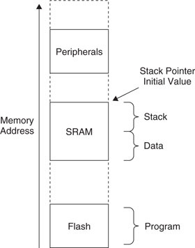
For simple application development, you can use the MSP for the whole program. That way you need to reserve memory that’s just large enough and set the MSP to the top of the stack. When determining the stack size required, besides checking the stack level that could be used by the software, you also need to check how many levels of nested interrupts can occur.
For each level of nested interrupts, you need at least eight words of stack. The processing inside interrupt handlers might need extra stack space as well.
Since the stack operation in the Cortex-M3 is full descending, it is common to put the stack initial value at the end of the static memory so that the free space in the SRAM is not fragmented.
For applications that use separate stacks for user code and kernel code, the main stack should have enough memory for the nested interrupt handlers as well as the stack memory used by the kernel code. The process stack should have enough memory for the user application code plus one level of stacking space (eight words). This is because stacking from the user thread to the first level of the interrupt handler uses the process stack.
Vector Table Setup
For simple applications that have fixed interrupt handlers, the vector table can be coded in ROM. In this case there is no need to set up the vector table during run time. However, in many applications, it is necessary to change the interrupt handlers for different situations. Then you will need to relocate the vector table to a writable memory.
Before the vector table is relocated, you might need to copy the existing vector table content to the new vector table location. This includes vector addresses for fault handlers, the NMI, system calls, and so on. Otherwise, invalid vector addresses will be fetched by the processor if these exceptions take place after the vector table relocation.
After the necessary vector table items are set up and the vector table is relocated, we can add new vectors to the vector table. For example:
Interrupt Priority Setup
By default, after a reset all exceptions with programmable priority are in priority level 0. For hard fault exceptions and NMI, the priority levels are —1 and —2, respectively. To program priority-level registers, we can take advantage of the fact that the registers are byte addressable, making the coding easier. For example:
In the Cortex-M3, the width of interrupt priority configuration registers is specified by chip manufacturers. The minimum width is 3 bits and the maximum is 8 bits. You can determine the implemented width by writing 0xFF to one of the priority configuration registers and reading it back. For example:
If your application needs to be portable, it is best to use priority levels 0x00, 0x20, 0x40, 0x60, 0x80, 0xA0, 0xC0, and 0xE0 only. This is because all Cortex-M3 devices should have these priority levels.
Do not forget to set up the priority for system exceptions and fault handler exceptions as well. If it is necessary for some of the important interrupts to have higher priority than other system exceptions or fault handlers, you’ll need to reduce the priority level of these system exceptions and fault handlers so that the important interrupts can preempt these handlers.
Enable the Interrupt
After the vector table and interrupt priority are set up, it’s time to enable the interrupt. However, two steps might be required before you actually enable the interrupt:
- If the vector table is located in a memory region that is write buffered, a Data Synchronization Barrier (DSB) instruction might be needed to ensure that the vector table memory is updated. In most cases the memory write should be completed within a few clock cycles. However, if your software needs to be portable between different Cortex-M3 products, this step ensures that the core will get the updated vector if the interrupt takes place immediately after being enabled.
- An interrupt might already be pended or asserted beforehand, so it might be needed to clear the pending status. For example, signal glitches during power-up might have accidentally triggered some interrupt generation logic. In addition, in some peripherals such as UART, noise from the UART receiver before connection might be mistaken as data and can cause an interrupt to be pended. Therefore, it might be necessary to check and clear the pending status of an interrupt before enabling it.
Inside the NVIC, two separate register addresses are used for enabling and disabling interrupts. This duality ensures that each interrupt can be enabled or disabled without affecting or losing the other interrupt enable status. Otherwise, through software-based READ-MODIFY-WRITE, changes in enable register status carried out by interrupt handlers could be lost. To set an enable, the software needs to compute the correct bit location in the SETEN registers in the NVIC and write a 1 to it. Similarly, to clear an interrupt, the software needs to write a 1 to the corresponding bit in the CLREN registers:

Likewise, we can write another subroutine for disabling IRQ:
Similar subroutines can be developed for setting and clearing IRQ pending status registers.
Accessing NVIC Interrupt Registers
Most registers in the NVIC can be accessed using word, half word, or byte transfers. Selecting the right transfer size can make your program development easier. For example, priority-level registers are best programmed with byte transfers. In this way there is no need to worry about accidentally changing the priority of other exceptions.
Exception/Interrupt Handlers
In the Cortex-M3, interrupt handlers can be programmed completely in C, whereas in ARM7, an assembly handler is commonly used to ensure that all registers are saved and, in cases of systems with nested interrupt support, the processor needs to switch to a different mode to prevent losing information. These steps are not required in the Cortex-M3, making programming much easier.
In assembler, a simple exception handler might look like this:
In many cases, the interrupt handler requires more than R0–R3 and R12 to process the interrupt, so we might need to save some other registers as well. The following example saves all registers that are not saved during the stacking process, but if some of the registers are not used by the exception handler, they can be omitted from the saved register list:

Since POP is one of the instructions that can start interrupt returns, we can combine the register restore and interrupt return in the same instruction.
Depending on the design of a peripheral, it might be necessary for an exception handler to program the peripheral to deassert the exception request. If the exception request from the peripheral to the NVIC is a pulse signal, then there is no need for the exception handler to clear the exception request. Otherwise, the exception handler will need to clear the exception request so that it won’t get pended again immediately after exception exit. In traditional ARM processors, a peripheral has to maintain its interrupt request until it is served, because the interrupt controllers designed for previous ARM cores do not have the pending memory.
With the Cortex-M3, if a peripheral generates interrupt requests in the form of pulses, the NVIC can store the request as a pending request status. Once the processor enters the exception handler, the pending status is cleared automatically. In this way, the exception handler does not have to program the peripheral to clear the interrupt request.
Software Interrupts
There are various ways to trigger an interrupt:
- External interrupt input
- Setting an interrupt pending register in the NVIC (see Chapter 8)
- Via the Software Trigger Interrupt Register (STIR) in the NVIC (see Chapter 8)
In most cases, some of the interrupts are unused and can be used as software interrupts. Software interrupts can work similarly to SVC, allowing accesses to system services. However, by default user programs cannot access the NVIC, except that they can access the NVIC’s STIR only if the USERSETMPEND bit in the NVIC Configuration Control register is set (see Table D.17 in Appendix D).
Unlike the SVC, software interrupts are not precise. In other words, the interrupt preemption does not necessarily happen immediately, even when there is no blocking from interrupt mask registers or other interrupt service routines. As a result, if the instruction immediately following the write to the NVIC STIR depends on the result of the software interrupt, the operation could fail because the software interrupt could invoke after the instruction is executed.
To solve this problem, use the DSB instruction. For example:

However, there is still another possible problem: If the interrupt mask register is set or if the program code generating the software interrupt is an exception handler itself, there could be a chance that the software interrupt cannot execute. Therefore, the program code generating the software interrupt should check to see whether the software interrupt has been executed. This can be done by having a software flag set by the software interrupt handler.
Finally, setting USERSETMPEND can lead to another problem. After this is set, user programs can trigger any software interrupt except system exceptions. As a result, if the USERSETMPEND is used and the system contains untrusted user programs, exception handlers will need to check whether the exception is allowed, because it could have been triggered from user programs. Ideally, if a system contains untrusted user programs, it is best to provide system services only via SVC.
Example with Exception Handlers
In Chapter 7, we mentioned that the starting vector table should contain a reset vector, an NMI vector, and a hard fault vector, since the NMI and hard fault handler can take place without any exception enabling. After the program starts, we can then relocate the vector table to a different place in the SRAM. Depending on the application, relocation of the vector table might not be necessary. In the following example, we put the newly relocated vector table in the beginning of the SRAM, and then the data variables follow after it:


This is a slightly long example. Let’s start from the end, the data region first.
In the data memory region (almost the end of the program), we define a space of 256 bytes as a vector table (SPACE 256). This allows up to 64 exception vectors to be stored here. You might want to change the size if you want less or more space for the vector table. The other software variables follow the vector table space, so the variable MyData1 is now in address 0x20000100.
In the beginning of the code, we defined a number of address constants for the rest of the program. So, instead of using numbers, we can use these constant names to make the program easier to understand.
The initial vector table now contains the reset vector, the NMI vector, and the hard fault handler vector. The preceding example code illustrates how to set up the exception vectors and does not contain actual NMI, hard fault, or IRQ handlers. Depending on the actual application, these handlers will have to be developed. The example uses BX LR as exception return, but that could be replaced by other valid exception return instructions.
After the initialization of registers, we copy the vector handlers to the new vector table in the SRAM. This is done by one multiple load and one multiple store instruction. If more vectors need to be copied, we can simply add extra load/store multiple instructions or increase the number of words to be copied for each pair of load and store instructions.
After the vector table is ready, we can relocate the vector table to the new one in the SRAM. However, to ensure that the transfer of the vector handler is complete, the DSB instruction is used.
We then need to set up the rest of the interrupt setting. The first one is the priority group setup. This needs to be done only once. In the example, two subroutines called SetupIrqHandler and EnableIRQ have been developed to make it easier to set up interrupts. Using the same code and simply changing the NVIC_SETEN to NVIC_CLREN, we can also add a similar function called DisableIRQ. After the handler and priority level have been set up, the IRQ can then be enabled.
Using SVC
SVC is a common way to allow user applications to access the API in an OS. This is because the user applications only need to know what parameters to pass to the OS; they don’t need to know the memory address of API functions.
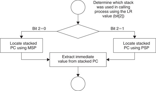
SVC instructions contain a parameter, which is 8-bit immediate data inside the instruction. The value is required for using the SVC instruction. For example:
![]()
Inside the SVC handler, it will need to extract the parameter back from the instruction. To do this, the procedures illustrated in Figure 11.2 can be used.
Here’s some simple assembly code to do this:

Once the calling parameter of the SVC is determined, the corresponding SVC function can be executed. An efficient way to branch into the correct SVC service code is to use table branch instructions such as TBB and TBH. However, if the table branch instruction is used, unless it is certain that the SVC calling parameter contains a correct value, you should do a value check on the parameter to prevent invalid SVC calling from crashing the system.
Since an SVC call cannot request another SVC service via the exception mechanism, the SVC handler should directly call another SVC function (for example, BL).
SVC Example: Use for Output Functions
Previously we developed various subroutines for output functions. Sometimes it is not good enough to use BL to call the subroutines—for example, when the functions are in different object files so that we might not be able to find out the address of the subroutines or when the branch address range is too large. In these cases, we might want to use SVC to act as an entry point for the output functions. For example:

To use SVC, we need to set up the SVC handler. We can modify the function that we have done for IRQ. The only difference is that this function takes an exception type as input (SVC is exception type 11). In addition, this time we have further optimized the code to use the Thumb-2 instruction features:
For svc_handler, the SVC calling number can be extracted as in the previous example, and the parameter passed to the SVC can be accessed by reading from the stack. In addition, the decision branches to reach various functions are added:
The svc_handler code should be put together with the outputting functions so that we can ensure that they are within the allowed branch range.
Notice that instead of the current contents of the register bank, the stacked register contents are used for parameter passing. This is because if a higher-priority interrupt takes place when the SVC is executed, the SVC will start after other interrupt handlers (tail chaining), and the contents of R0–R3 and R12 might be changed by the interrupt handler. This is caused by the characteristic that unstacking is not carried out if there is tail chaining of interrupts. For example:
- A parameter is put in R0 as a parameter.
- SVC is executed at the same time a higher-priority interrupt takes place.
- Stacking is carried out, and R0–R3, R12, LR, PC, and xPSR are saved to the stack.
- The interrupt handler is executed. R0–R3 and R12 can be changed by the handler. This is acceptable because these registers will be restored by hardware unstacking.
- The SVC handler tail chains the interrupt handler. When SVC is entered, the contents in R0–R3 and R12 can be different from the value when SVC is called. However, the correct parameter is stored in the stack and can be accessed by the SVC handler.
Make the Most of the Addressing Modes
From the code examples of the SetupirqHandler and SetupExcpHandler routines, we find that the code can be shortened a lot if we utilize the addressing mode feature in the Cortex-M3. In SetuplrqHandler, the destination address of the IRQ vector is calculated, and then the store is carried out:
In SetupExcpHandler, the operation Step 4–6 are reduced to just one step:
In general, we can reduce the number of instructions required if the data address is like one of these:
- Rn + 2N*Rm
- Rn +/– immediate_offset
For the SetupirqHandler routine, the shortest code we can get is this:
Using SVC with C
In most cases, an assembler handler code is needed for parameter passing to SVC functions. This is because the parameters should be passed by the stack, not by registers, as explained earlier. If the SVC handler is to be developed in C, a simple assembly wrapper code can be used to obtain the stacked register location and pass it on to the SVC handler. The SVC handler can then extract the SVC number and parameters from the stack pointer information. Assuming that RealView Development Suite (RVDS) or KEIL RealView Microcontroller Development Kit is used, the assembler wrapper can be implemented with Embedded Assembler:

The rest of the SVC handler can then be implemented in C using R0 as input (stack frame starting location), which is used to extract the SVC number and passing parameters (R0–R3):
Note that SVC cannot return results to the calling program in the same way as in normal C functions. Normal C functions return values by defining the function with a data type such as unsigned int func( ) and use return to pass the return value, which actually puts the value in register R0. If an SVC handler put return values in register R0 to R3 when exiting the handler, the register values would be overwritten by the unstacking sequence. Therefore, if an SVC has to return results to a calling program, it must directly modify the stack frame so that the value can be loaded into the register during unstacking.
To call an SVC inside a C program for ARM RealView Development Suite (RVDS) or KEIL RealView Microcontroller Development Kit (RV-MDK), we can use the _ _svc compiler keyword. For example, if four variables are to be passed to an SVC function number 3, an SVC named call_svc_3 can be declared as:
![]()
This will then allow the C program code to call the system call by:
Detailed information on using the _ _svc keyword in RealView Development Suite or RealView C Compiler can be found in the RVCT 3.0 Compiler and Library Guide (Ref 6).
For users of the GNU tool chain, since there is no _ _svc keyword in GCC, the SVC has to be accessed by inline assembler. For example, if the SVC call number 3 is needed with one input variable and it returns one variable via register R0 (according to the AAPCS, Ref 5, the first passing variable will use register R0), the following inline Assembler code can be used to call the SVC:

This inline assembler code can be broken down into the following parts, with input data specified by r (MyDataIn) and no output field (indicated as "" in the preceding code):
![]()
More examples using inline Assembler in the GNU tool chain can be found in Chapter 19 of this book. For complete details on passing parameters to or from inline Assembler, refer to the GNU tool chain documentation.