
CHAPTER 20 Getting Started with the KEIL RealView Microcontroller Development Kit
In This Chapter:
• Overview
• Getting Started with μVision
• Outputting the “Hello World” Message Via UART
Overview
Various commercial development platforms are available for the Cortex-M3. One of the popular choices is the KEIL RealView Microcontroller Development Kit (RealView MDK). The RealView MDK contains various components:
- μVision
- Integrated Development Environment (IDE)
- Debugger
- Simulator
- RealView Compilation Tools from ARM
- RTX Real-Time Kernel
- Detailed startup code for microcontrollers
- Flash programming algorithms
- Program examples
For learning about the Cortex-M3 with RealView MDK, it is not necessary to have Cortex-M3 hardware. The μVision environment contains an instruction set simulator that allows testing of simple programs that do not require a development board.
RealView MDK can also be used with other tool chains, such as:
- GNU ARM Compiler
- ARM Development Suite (ADS)
A free evaluation CD-ROM for the KEIL tool can be requested from the KEIL Web site (www.keil.com). This version is also included in the Luminary Micro Stellaris Evaluation Kit1 (www.luminarymicro.com).
Getting Started with μVision
A number of examples are provided with the RealView MDK, including some examples for the Luminary Micro Stellaris microcontroller products. These examples provide a powerful set of device driver libraries that are ready to use. It’s easy to modify the provided examples to start developing your application, or you can develop your project from scratch. The following examples illustrate how this is done. The examples shown in this chapter are based on the v3.03 beta and on Luminary Micro LM32811 devices.
After installing the RealView MDK, you can start the μVision from the program menu. After installation, the μVision might start with a default project for a traditional ARM processor. We can close the current project and start a new one by selecting New Project in the pull-down menu (see Figure 20.1).

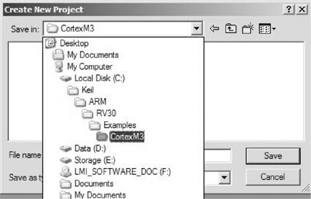
Here a new project directory called CortexM3 is created (see Figure 20.2).
Now we need to select the targeted device for this project. In this example, the LM3S811 is selected (see Figure 20.3).

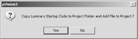
The software will then ask if you would like to use the default startup code. In this case, we select Yes (see Figure 20.4).
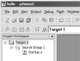
Now we have a project called Hello with only one file, called Startup.s (see Figure 20.5).
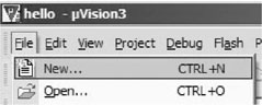
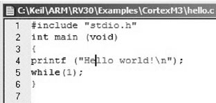
We can create a new C program file containing the main program (see Figure 20.6).
A text file is created and saved as hello.c (see Figure 20.7).
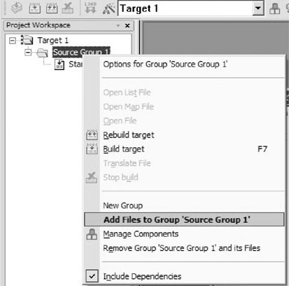
Now we need to add this file to our project by right-clicking Source Group 1 (see Figure 20.8).
Renaming the Target and File Groups
The target name Target 1 and file group name Source Group 1 can be renamed to give a clearer meaning. This is done by clicking Target 1 and Source Group 1 in the project workspace and editing the names from there.
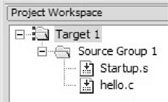
Select the hello.c that we created and then close the Add File window. Now the project contains two files (see Figure 20.9).
We also need to set a linker setting to define the entry point of the program. We do this by adding—entry Reset_Handler in the Misc Controls box (see Figure 20.10). This option defines the starting point of the program. Reset_Handler is an instruction address that can be found in the Startup.s.

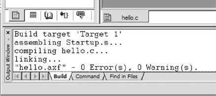
We can now compile the program. Right-click Target 1 and select Build target (see Figure 20.11).

You should see the compilation success message in the output window (see Figure 20.12).
Outputting the “Hello World” Message Via UART
In the program code we created, we used the printf function in the standard C library. Since the C library does not know about the actual hardware we are using, if we want to output the text message using real hardware such as the UART on a chip, we need additional code.
As mentioned earlier in the book, the implementation of output to actual hardware is often referred to as retargeting. Besides creating text output, the retargeting code might also include functions for error handling and program termination. In this example, only the text output retargeting is covered.
For the following code, the “Hello world” message is output to UART 0 of the LM3S811 device. The target system used is the Luminary Micro LM3S811 evaluation board. The board has a 6 MHz crystal as a clock source, and an internal Phase Locked Loop (PLL) module that can step up the clock frequency to 50 MHz after a simple setup process. The baud rate setting is 115200 and is output to HyperTerminal running on a Windows PC.
To retarget the printf message, we need to implement the fputc function. In the following code we have created a fputc function that calls the sendchar function, which carries out the UART control:
The SetupClockFreq routine sets the system clock to 50 MHz. The setup sequence is device dependent. The subroutine can also be used to set the clock frequency to 6 MHz if the CLOCK50 MHZ compile directive is not set.
The UART initialization is carried out inside the Uart0Init subroutine. The setup process includes setting up the baud rate generator to provide a baud rate of 115200; configuring the UART to 8-bit, no parity, and 1 stop bit; and switching the GPIO port to alternate function because the UART pins are shared with GPIO port A. Before accessing the UART and the GPIO, the clocks for these blocks must be turned on. This is done by writing to SYSCTRL_RCGC1 and SYSCTRL_RCGC2.
The retargeting code is carried out by fputc, a predefined function name for character outputs. This function calls the sendchar function to output the character to the UART. The sendchar function outputs an extra carriage return character as a new line is detected. This is needed to get the text output correct on HyperTerminal; otherwise the new text in the next line will overwrite the previous line of text.
After the hello.c program is modified to include the retargeting code, the program is compiled again.
Testing the Software
If you’ve got the Luminary Micro LM3S811 evaluation board, you can try out the example by downloading the compile program into Flash and getting the “Hello world” message display output from the HyperTerminal. Assuming that you have set up the software drivers that come with the evaluation board, you can download and test the program by following these steps.
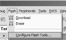
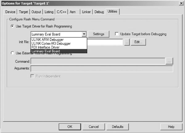
First, set up the Flash download option. This can be accessed from the pull-down menu, as shown in Figure 20.13.
Inside this menu, we select the Luminary Evaluation Board as the download target (see Figure 20.14).
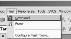
Then we can download the program to the Flash on a chip by selecting Download in the pull-down menu (see Figure 20.15).
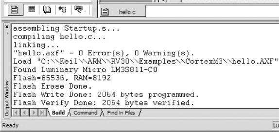
The message shown in Figure 20.16 will appear, indicating that the download is complete. Note: If you have the board already running with HyperTerminal, you might need to close HyperTerminal, disconnect the USB cable from the PC, and reconnect before programming the Flash.
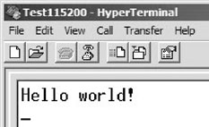
After the programming is completed, you can start HyperTerminal and connect to the board using the Virtual COM Port driver (via USB connection) and get the text display from the program running on the microcontroller (see Figure 20.17).
Using the Debugger
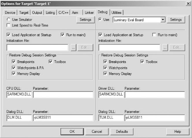
You can use the debugger in µVision to connect to the Luminary Evaluation Board to debug your application. By right-clicking the project Target 1 and selecting Options, we can access the debug option. In this case we select to use the Luminary Eval Board for debugging (see Figure 20.18).
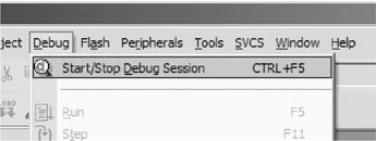
We can then start the debug session from the pull-down menu (see Figure 20.19). Note: If you have the board already running with HyperTerminal, you might need to close HyperTerminal, disconnect the USB cable from the PC, and reconnect before starting the debug session.
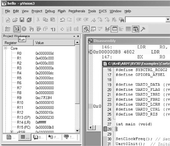
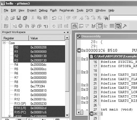
When the debugger starts, the IDE provides a register view to display register contents. You can also get the disassemble code window and see the current instruction address. In Figure 20.20 we can see that the core is halted at the Reset_Handler.

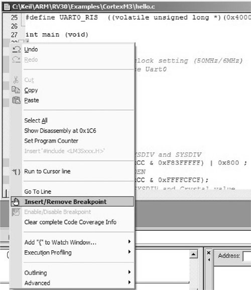
For testing, a breakpoint is set to stop the program execution at the beginning of main. This can be done by right-clicking the program code window and selecting Insert/Remove Breakpoint (see Figure 20.21). Note: We could also use the Run to main( ) feature in the debug option to get the program execution stop at the beginning of main.
The program execution can then be started using the Run button on the tool bar (see Figure 20.22).
The program execution is then started, and it stops when it gets to the start of the main program (see Figure 20.23).
We can then use the stepping control of the tool bar to test our application and examine the results using the register window.
The Instruction Set Simulator
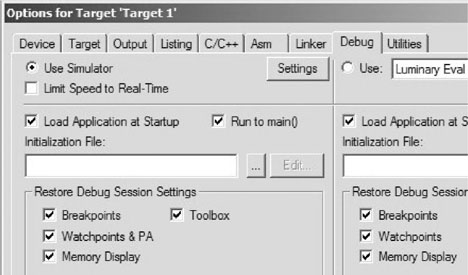
The µVision IDE also comes with an instruction set simulator that can be used for debugging applications. The operation is similar to using the debugger with hardware and is a useful tool for learning the Cortex-M3. To use the instruction set simulator, change the debug option of the project to Use Simulator (see Figure 20.24). Note that the simulator cannot simulate all hardware peripheral behaviors, so the UART interface code might not simulate correctly.
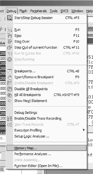
When using the simulator for debugging, you might also need to adjust the memory setting of the simulation. This is done by accessing the Memory Map option after starting the debugging session (see Figure 20.25).
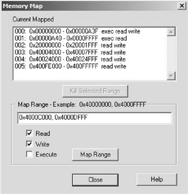
For example, you might need to add the UART memory address range to the memory map (see Figure 20.26). Otherwise you will get an abort exception in the simulation when you try to access the UART.
Modifying the Vector Table
In the previous example, the vector table is defined inside the file Startup.s, which is a standard startup code the tool prepares automatically. This file contains the vector table, a default reset handler, a default NMI handler, a default hard fault handler, and a default interrupt handler. These exception handlers might need to be customized or modified, depending on your application. For example, if a peripheral interrupt is required for your application, you need to change the vector table so that the Interrupt Service Routine (ISR) you created will be executed when the interrupt is triggered.
The default exception handlers are in the form of assembly code inside Startup.s. However, the exception handlers can be implemented in C or in a different assembly program file. In these cases, the IMPORT command in the assembler will be required to indicate that the interrupt handler address label is defined in another file. The next section contains an example that illustrates how this command is used as well as illustrating simple exception handling in C.
Stopwatch Example with Interrupts
This example includes the use of exceptions such as SYSTICK and the interrupt (UART0). The stopwatch to be developed has three states, as illustrated in Figure 20.27.
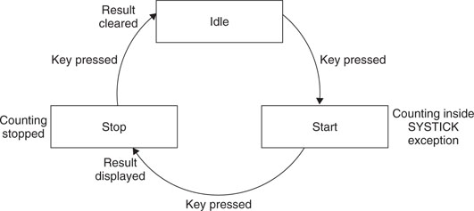
Based on the previous example, the stopwatch is controlled by the PC using the UART interface. To simplify the example code, we fix the operating speed at 50 MHz.
The timing measurement is carried out by the SYSTICK, which interrupts the processor at 100 Hz. The SYSTICK is running from the core clock frequency at 50 MHz. Every time the SYSTICK exception handler is executed, if the stopwatch is running, it increments the counter variable TickCounter.
Since display of text via UART is relatively slow, the control of the stopwatch is handled inside the exception handler, and the display of the text and stopwatch value is carried out in the main (Thread level). A simple software state machine is used to control the start, stop, and clear of the stopwatch. The state machine is controlled via the UART handler, which is triggered every time a character is received.
Using the same procedure we used for the “Hello World” example, let’s start a new project called stopwatch. Instead of having hello.c, a C program file called stopwatch.c is added:


The UART initialization has changed slightly to enable interrupts when a character is received via the UART interface. To enable the UART interrupt request, the interrupt has to be enabled at the UART interrupt mask register as well at the NVIC. For the SYSTICK, only the exception control at the SYSTICK Control and Status register needs to be programmed.
In addition, a number of extra functions are added, including the UART and SYSTICK handlers, display functions, and SYSTICK initialization. Depending on the design of the peripheral, an exception/interrupt handler might need to clear the exception/interrupt request. In this case, the UART handler clears the UART interrupt request using the Interrupt Clear Register (UART0_ICR). The startup code Startup.s is also modified to set up the exception handlers (see Figure 20.28).
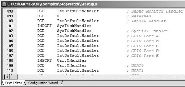
Since the handlers are in the C program file, the IMPORT command is needed so that the assembler knows that the address label is from a different file.
After the program is compiled and downloaded to the evaluation board, it can then be tested by connecting to a PC running HyperTerminal. Figure 20.29 shows the result.

Note: If the test board is a Luminary Micro evaluation board and the Virtual COM Port is used for the UART communication, this example might not work correctly (keystrokes in HyperTerminal cannot be sent to the board) due to a problem with the Virtual COM port device driver. In this case, you might need to test the program on a different PC with only the device driver and without the RealView MDK installation.
1Stellaris is a registered trademark of Luminary Micro.