
![]()
Arduino, Raspberry Pi, and Programming Physical Things
In Chapter 1, we discussed the different ways to think about using hands-on making to learn various subjects. In this chapter we introduce the basic nuts and bolts of commonly used open source electronics (microprocessors, single-board computers, and other components) and suggest paths to get started making things with these technologies.
Some of the components in this chapter (Arduino and Raspberry Pi) can and have been used for extremely sophisticated projects, up to and including an Arduino-controlled small spacecraft (the Ardusat, www.ardusat.com). We cover slightly less-ambitious applications of Arduino-class microcontrollers in Chapters 4, 6, 7 and 8. An Arduino is a microcontroller, which means it is not a whole computer. It is not intended to run multiple programs, drive a screen, and so on. It is meant just to control or monitor one or more devices. Raspberry Pi boards, on the other hand, really are full-blown computers and can run (moderate-sized) programs, handle a keyboard, and do many other things.
The big challenge of learning to use these technologies is that you have to learn several things at once. In most cases, you will need to write computer code in an appropriate integrated development environment (IDE) and be able to wire physical circuits, not to mention try to figure out what your system should actually do (Figure 2-1). If you are learning all that at the same time, it can be hard to figure out what is wrong if things do not work.
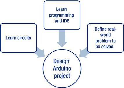
Figure 2-1. Learning Arduino
This chapter is largely Rich’s world, but Joan has jumped in quite a bit to try to make things simpler. Some of this chapter might be a little more detailed than you want at this stage; in a few places, we’ve given you permission to skip to the next section if you want to. Since this chapter was a very tight blending of both our points of view, we just say “we” in this chapter rather than jump back and forth between our points of view. We are sure you will see a bit of both hacker and educator in the coming sections.
This field has a lot of terminology, and it is difficult to unravel it in an orderly way. So, we may use a word before we define it in depth. When we do that, we will give you a pointer to later in the chapter, so you can hold the term in your mind and see it discussed just a little farther on.
We have tried to minimize jargon as much as possible, but you will see a lot of the words here when you go to buy supplies, enroll in a class, or buy more detailed books, and we did not want to underprepare you, either. At the end of the chapter, we summarize what you need to learn for the different paths through this space and discuss what different key components typically cost so that you can budget as you get started. This is not so much a how-to chapter (we reference other books for that) as it is a why-would-you chapter. We want you to understand what you might do with a Raspberry Pi or Arduino and develop a basis of understanding that will carry you through the later, more specific application-focused chapters.
Some of the other electronics we talk about primarily in Chapter 8 (Circuit Stickers, LightUp) are intended to be used in more traditional classroom or home settings. They are geared toward simpler aspirations such as being able to design a basic circuit safely and as a gateway to more difficult programming.
One way to avoid having to deal with everything at once is to first learn how to write programs in a computer language called (confusingly) Processing. Processing is a programming language and development environment that is similar to those used by Arduinos. We introduce that here first as an option.
More typically, though, people learn how to use the technologies in this chapter by creating progressively more complex projects and thus learn incrementally more about each of the aspects. If you have some guidance, this is fine, but if not it can be difficult to know the difference between a “hard” and “easy” project before you embark. Figure 2-2 shows how we walk you through the possible learning paths. First we talk about Processing; then we backtrack a bit to give you some material about circuits so the rest is comprehensible; then finally we move on to the Arduino ecosystem itself. In later chapters we talk more about where else you can go with all this.
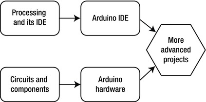
Figure 2-2. The paths we follow in this book
Processing and Arduino
One way to avoid trying to go in too many directions at once is to learn some basic commands in the computer language called Processing and then learn how to program an Arduino. Programming an Arduino is very similar to programming in Processing. Processing lets you use computer code to draw things on a screen in an animated way, so it could let students program an animation of a moving lever, for example. Arduinos allow you to control physical objects such as making a simple actual machine move.
Learning Processing
The Processing computer language is a simple language that is built on Java and is a lot like the C programming language. It is very good for creating animations. To test it out, go to the Processing tutorials page at https://processing.org/tutorials/overview/ and download the Processing IDE.
An IDE is software that allows you to develop and run code. The Processing IDE has a simple interface for writing and running code in the Processing language, and there is a reference for the IDE’s interface (https://processing.org/reference/environment/). Once the IDE is installed, paste in some of the examples. Doing so will get you comfortable programming simple animations. If you then want to take the next step up and incorporate physical hardware into your simulations, you would then move to the Arduino IDE, covered in the next section, which is based on Processing’s and is laid out very similarly.
Arduino and Its Ecosystem
Arduino is an open source platform comprised of a family of microcontroller boards and an IDE used for programming them. A microcontroller is an integrated circuit (IC), or computer chip, that includes a processor core, programmable input/output (I/O), and memory used to store the programs and data being used by the processor. To develop a program to run on an Arduino, you install the IDE on a laptop or desktop computer (a Mac, Windows, or Linux machine). Once you have written the code for the Arduino, you send it to the board via USB.
You can download the IDE from the Arduino main page (http://Arduino.cc). Figure 2-3 shows an Arduino and a Raspberry Pi next to each other for scale. The Arduino has been screwed down onto some acrylic next to a breadboard, which we talk about later.
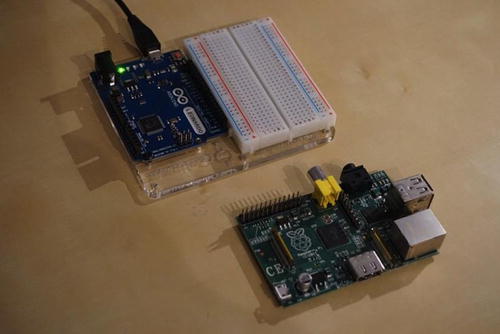
Figure 2-3. An Arduino (top) mounted with a breadboard, and a Raspberry Pi
An Arduino is essentially a computer built into a single chip that—although much less powerful than a desktop computer, or in most cases even a modern cellphone—is much more powerful than room-sized computers were in the 1970s. The Arduino’s IDE is a text editor used for writing programming code to instruct the microcontroller on what to do, with built-in functions for compiling code written by the user into a series of simple instructions that the microcontroller will understand, and for communicating with the microcontroller to copy those instructions to its internal flash memory. An Arduino lets you interact with the physical world in some way that you program. You can program it to read data from a light sensor and start up a light-emitting diode (LED) if it gets dark, for example.
There are a variety of boards available with different shapes, sizes, and capabilities. Some of these are officially endorsed by the Arduino team and carry the Arduino name, though many are based to varying degrees on the open source designs that have been published for one of the official Arduino boards, or on one of the other unofficial boards. These unofficial boards are allowed to use the Arduino designs, but not the Arduino name except to say that they are Arduino-compatible. Many have names that include either the Ardu- prefix or the -duino suffix as shorthand for Arduino-compatible.
Official Arduino boards come in a range of prices starting around $20 (costs in this book are in U.S. dollars), whereas clones start at around $10 for the basic versions. Some counterfeit Arduino boards (ones that use both the open source designs that they are allowed to and the trademarked names and appearance that they are not) can be found for as little as $2.50. Although they usually work, they are likely to include inferior components, and our community discourages people from buying them for this reason—and because counterfeiting is an abuse of the spirit of open source (see Chapter 9).
![]() Tip There are many good books and websites about Arduinos. However, it is important to find some beginner projects first. Just as you would probably not start teaching someone to drive at the Indy 500, it is best to learn these environments with relatively simple projects and work your way up. Beginning Arduino by Michael McRoberts, 2nd Edition (Apress, 2013) starts with a project to blink one LED and goes up from there. The Instructables website (www.instructables.com) has many different DIY projects; if you search on “beginner Arduino” or “beginner Raspberry Pi” on the site, you will find appropriate projects (although the definition of “beginner” on that site might be a little aggressive in some cases).
Tip There are many good books and websites about Arduinos. However, it is important to find some beginner projects first. Just as you would probably not start teaching someone to drive at the Indy 500, it is best to learn these environments with relatively simple projects and work your way up. Beginning Arduino by Michael McRoberts, 2nd Edition (Apress, 2013) starts with a project to blink one LED and goes up from there. The Instructables website (www.instructables.com) has many different DIY projects; if you search on “beginner Arduino” or “beginner Raspberry Pi” on the site, you will find appropriate projects (although the definition of “beginner” on that site might be a little aggressive in some cases).
Arduinos and Arduino-compatible boards may not have as much computing power as a typical personal computer, but they can do some things a laptop computer cannot. If you want to connect to any electronic devices that are too simple to have a USB port or equivalent interface, your Mac or Windows computer probably will not be able to do it without something like an Arduino that is programmed to translate that data for it. Arduinos are commonly used for a variety of programmable electronics projects, including robots (Chapter 4), drones and other autonomous or semi-autonomous vehicles, 3D printing and other computer-controlled manufacturing (Chapter 3), translating and relaying or logging data from sensors (Chapter 6), wearable electronics (Chapter 7), playful computer interfaces (Chapter 8), and many other tasks that involve linking simple electrical interfaces either with their limited computing power or translating that data into the more sophisticated protocols required by a more powerful computer. Arduinos are also smaller and cheaper than a typical laptop or desktop, and use less power, which makes them better for embedding in projects. (See the next section for more detail.)
An Arduino, unlike a Mac or Windows computer, does not run an operating system or multitask between multiple programs. It has a single program that begins running when it powers up, after a brief pause for the bootloader to check whether you are trying to upload a new program, and continues until the power is switched off. This makes it better for certain operations where precise timing is critical, such as sending commands to move stepper motors. (A stepper motor is a motor which turns a shaft in discrete, precise increments, often used for robotics projects, as opposed to a brushed motor that just turns continuously when a voltage is applied; see the section on stepper motors later in this chapter.) Computer-numerically-controlled (CNC) machine tools like mills and lathes, which use stepper motors to move their tools, are typically built with a computer controller, but using an Arduino-equivalent to control them might work better for precise timing. Open source 3D printers are typically built this way.
All the current Arduino boards use chips made by Atmel Corporation, but there are other similar products. As of this writing, most Arduino boards and their clones use 8-bit microcontrollers from Atmel’s AVR family of products, but Microchip Technology’s PIC family of products has similar capabilities, and Parallax Inc.’s BASIC Stamp is also comparable. Religious wars are fought on the Internet over which is best, and each product line (as well as each individual product) has its own strengths and weaknesses compared to the rest of the ecosystem. It is our opinion that the ubiquity and beginner-friendliness of the Arduino environment makes it a clear winner, even when the others might be more powerful. Although the others might be better for specific uses, the wealth of free information and shared projects make the Arduino much more useful for those just getting started.
Interfacing an Arduino with the Real World
The power of an Arduino is that it can interact with the physical world. This section talks in some detail about how that works. Figure 2-4 illustrates the general idea.
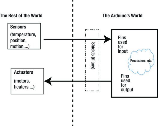
Figure 2-4. How an Arduino interacts with the physical world
Pins on a computer chip are electrical contacts facing down toward the circuit board that are either soldered directly to the board or connected to a socket that is. Some pins are used to provide power to the chip, but most are used to either take a signal in from something (input pins) or send a signal to something (output pins). Arduinos process the signals coming in and then send out signals based on what they perceive. This part is a little technical, but if you are doing a first pass through now, we suggest you come back to this section later, because some of the insights here will be important in later chapters that talk about how to use Arduinos and associated technologies in bigger projects. We give you our permission to skip ahead to the section “Circuit Design and Components” if you feel like you do not need to know details right now.
Arduinos have General Purpose Input/Output (GPIO) pins that can be configured either as inputs that can read things like analog voltages and pulse frequencies that various sensors produce, or as outputs that can trigger LEDs, motors, small display modules, and so on. Any of the GPIO pins on an Arduino can be configured for use as either a digital input or a digital output. You can change which mode is being used at any time. Each program generally sets each pin’s mode at the beginning and does not change it, though there are exceptions.
People typically think of digital hardware as being binary systems that have just two values (think on and off). Depending on context, these values might be true and false, or 1 and 0, or HIGH and LOW. The Arduino has some tricky ways of finessing this to get other values in between to emulate a continuous (analog) signal. You need to do this if you are trying to control a heater to be between 60 and 75 degrees, for example. In this section, we talk about this for output and input pins, which are handled a bit differently. This topic is, of necessity, a bit complex, and we are just giving the general flavor here of what is possible and what is easy and hard.
Output Pins
If a pin is being used as an output pin, it will be set either to LOW (0 volts, which is known as ground or GND), representing the value 0 or false, or HIGH, representing the value 1 or true. Setting pins to HIGH means the Arduino raises the pin to its logic voltage, either 5V or 3.3V, usually referred to as VCC for historical reasons. In either case, the amount of current that can travel through the pin is limited. Typically it is around 40 milliamps, but may be less for some, like the newer ARM-based Arduino boards. To drive loads that need more power requires additional components.
We mentioned that is possible to finesse the system to have some of the pins output an analog signal. They do this by using a technique called pulse width modulation (PWM) on the signal. Arduino calls this function analogWrite, which allows it to put out a value between 0 and 1. The Arduino does not actually put out a lower voltage (you can’t set a pin on a 5V Arduino to put out 2.5V). Instead, it quickly switches the pin between 0 and 1 several hundred times per second.
A typical PWM frequency for an Arduino is 490 cycles per second, or hertz (Hz), which means that for any PWM setting, the pin will go HIGH and then LOW 490 times each second. The total time of each cycle is fixed, but the proportion of that cycle that it spends HIGH vs. LOW is variable. analogWrite uses a scale of 0–255, so a value of 0 is fully off (100% LOW), a value of 255 is fully on (100% HIGH), and a value of 127 is 50% HIGH, 50% LOW. The percentage of each cycle that a PWM signal spends in the HIGH state is called the duty cycle. Although you can write a program that creates pulses like these of a certain length by running in a loop (a method called bit-banging), doing so makes it difficult to do anything else at the same time. This is particularly true because an Arduino does not have an operating system to manage multitasking. The microcontroller is equipped with hardware functions that will sustain the PWM signal while the processor does other things until the pin is told to do something else.
![]() Note Why not output an analog voltage? Most devices that an Arduino controls in this way are either being powered directly by the pin (if they can be powered by the Arduino’s logic-level voltage and use a low enough current for the pin to source, such as an LED) or are having their power switched off and on by the Arduino’s digital signal through a device that allows it to switch higher voltage and current, such as a that required to run a brushed DC motor. In either of these cases, the response to a decreased voltage is less linear than the response to a decreased duty cycle. An LED will not light up at all if the voltage is too low, and does not rise in brightness proportionally to the voltage of its supply, but by turning it off and on at a speed much faster than the human eye can perceive, the apparent brightness will be reduced. Likewise, if you want to control the speed of a brushed (not stepper) motor’s rotation precisely, you can make that speed proportional to the duty cycle of a signal turning the motor power either full on or full off. Common motor drivers controlled this way are digital devices that, like the Arduino itself, do not even have the ability to drive an analog voltage. This process works better than using an analog voltage for a variety of reasons.
Note Why not output an analog voltage? Most devices that an Arduino controls in this way are either being powered directly by the pin (if they can be powered by the Arduino’s logic-level voltage and use a low enough current for the pin to source, such as an LED) or are having their power switched off and on by the Arduino’s digital signal through a device that allows it to switch higher voltage and current, such as a that required to run a brushed DC motor. In either of these cases, the response to a decreased voltage is less linear than the response to a decreased duty cycle. An LED will not light up at all if the voltage is too low, and does not rise in brightness proportionally to the voltage of its supply, but by turning it off and on at a speed much faster than the human eye can perceive, the apparent brightness will be reduced. Likewise, if you want to control the speed of a brushed (not stepper) motor’s rotation precisely, you can make that speed proportional to the duty cycle of a signal turning the motor power either full on or full off. Common motor drivers controlled this way are digital devices that, like the Arduino itself, do not even have the ability to drive an analog voltage. This process works better than using an analog voltage for a variety of reasons.
Only certain pins have hardware PWM capability, though any pin can be used for bit-banging, which is often called soft PWM because it is a software implementation of the protocol rather than the built-in hardware implementation. Other protocols that are not natively supported in hardware can be implemented in software, such as Pulse Frequency Modulation (PFM), in which information is encoded as the frequency of a series of pulses, rather than its duty cycle.
Input Pins
If a pin is configured as an input, it will not try to provide a HIGH or LOW voltage digital signal. Instead, it will stop pulling strongly in one direction or the other (a state called floating) and allow whatever is connected to it to determine the voltage. If the voltage is close to the Arduino’s logic voltage, a digitalRead will tell you that it is HIGH, and if it’s close to ground, it will read as LOW. digitalRead always returns one of these two responses, and there is a zone of uncertainty in the middle where the output is less predictable. Therefore, the circuit should have a voltage that is close to one of these values, but never higher than the logic voltage level or lower than ground.
Certain pins can be used to read analog voltages between these two values with analogRead, and unlike analogWrite, the chip’s analog-to-digital converter (ADC) actually does use analog voltages, which it converts into digital values. ADC readings have a range of 0–1023, so on a 5V Arduino board, 5V reads as 1023, ground reads as 0, and 2.5V reads as 511.
The Arduino’s chip has another way to interface with other components. Although many simple components are controlled by switching power on and off, many components useful as sensors simply reduce a voltage by a variable amount relative to what they are sensing. Some components are smarter and do some processing on their own. Several data protocols have been designed to allow these simple devices to talk back and forth. These are similar to protocols like USB that a PC uses to talk to other devices, but they are simpler and slower because they are designed for devices with minimal processing power.
The microcontrollers used for Arduino boards have hardware implementations of Inter-Integrated Circuit (I2C) and Serial Peripheral Interface (SPI) for communication with other components. They also typically use the RS-232 protocol to talk to another chip that translates a computer’s USB connection for programming the Arduino and for communicating with the program running on it. Some newer Arduinos are built with microcontrollers that have native hardware support for the USB protocol as well.
An Arduino on its own is not good for much. Most Arduinos have a single LED connected to one of their digital outputs that they can turn on and off. The canonical first project on an Arduino is to make this LED blink to test that the hardware and software work, but a single blinking LED is not very useful on its own. Doing more useful things requires connecting to other devices. You can do this by attaching wires to the individual sockets on the board, but many projects are common enough that people have designed other circuit boards to connect to the Arduino for that purpose. In general electronics terminology, such a board is known as a daughterboard—an ancillary board that connects to a main board, or motherboard, to extend its functionality or capabilities.
Most Arduino boards share a common layout for the I/O pins, and there is a special type of daughterboard known as an Arduino shield that matches this layout. A shield is designed to plug in to the top of an Arduino board (look back at Figure 2-4 for a visual). Shields use all their pins to mechanically join it to the Arduino board, though some pins may not be electrically connected. A shield typically has at least one chip that is either a sensor or that changes the Arduino’s output. For instance, it might be switching higher voltages or more current so that the Arduino can control motors, brighter lights than the single basic LED described in the previous paragraph, speakers, or anything that is not directly compatible with the logic-level signals that the microcontroller puts out.
Some shields do some processing of their own and use low-level protocols and translate signals for the Arduino in the same way an Arduino can translate them for a PC’s USB interface, but most simply use an analog voltage or a pattern of digital pulses. A shield may do more than one of these things, such as a motor driver that allows the Arduino to control the power going to a motor. The motor in turn has an encoder that returns one or more pulses to one of the Arduino’s inputs every time the motor completes a rotation so that the Arduino can sense how fast the motor is turning. Each shield generally does not use all the Arduino’s pins for its own function, but because a shield covers up all the I/O pins, it typically has another set of the same connectors on the top so that the rest of the pins will be accessible. If you have two shields that do not use any of the same I/O pins, you can usually stack one on top of the other and use both at the same time. There are also several proto shields available that simply have space for you to build your own circuit, either on a breadboard (discussed later in this chapter) attached to the shield or soldered to a similar grid of holes.
For example, the ArduSensor Shield (see www.qtechknow.com for more) shown in Figure 2-5 connects to an Arduino and gives a user the ability to connect up to four sensors (breakout boards that detect flex, force, light, and temperature).
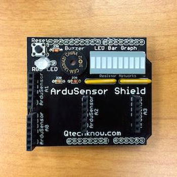
Figure 2-5. A shield (courtesy of Qtechknow.com)
Stepper Motors
Arduinos are often used to control stepper motors, which are discussed in detail in Chapter 4. For example, 3D printers (Chapter 3) typically use a modified Arduino-compatible controller. A stepper motor is designed to hold something in a fixed position. By cycling the polarities of the two or more electromagnetic windings, the motor transitions from one position to the next, turning the shaft a bit more with each transition to make it rotate. These polarity changes must be precisely timed to ensure smooth movement of the motor. A microcontroller like the one an Arduino board uses is designed for that type of application, so although it is a slower processor than you would find in a PC, it is doing less and its timing is more predictable, making it better suited to the job.
Understanding electronics requires that you also understand a little bit of the physics behind the hardware. What is voltage? What is current? What about resistance? These measurements describe the movement of electrons through a conductor.
Voltage, measured in volts (symbolized by the letter V), is a pressure that causes electrons to move through a conductor, like water being pumped through a closed loop of tubes with something that resists the flow somewhere in the system, such as a valve. The pump pulls water in, creating a low pressure at its input, and pushes it out of its output end, creating a higher pressure. When you connect these high- and low-pressure areas, water flows from the high-pressure area to the low-pressure area. A greater pressure through a pipe causes more water to flow from one end to the other (or the same amount of water to flow faster), and a greater voltage causes more flow of electrons.
Current, measured in amperes (symbolized by the letter A), or amps for short, is the flow of electrons. Resistance, measured in ohms (symbolized by the Greek letter omega, Ω) resists the flow of current, like a valve resisting the flow of water. If the valve is mostly closed, the resistance is high, and very little water will flow. But an open valve is like a low-resistance path that allows more current to flow. The relationship of these three terms is calculated using Ohm’s law: voltage equals current times resistance.
In order for current to flow, a circuit must have at least two different voltage potentials (levels of pressure) so that there can be a voltage or potential difference across the load (whatever the circuit is powering). These voltage potentials have very little meaning except in relation to one another, and the zero point of the measurement is arbitrary. By convention, one voltage level in a circuit, generally the lowest, is specified as 0V (zero volts), and all other voltages are measured in reference to that one. This reference point is known as ground, which is not to be confused with the earth ground connected to the third prong of a wall socket.
To build your own Arduino projects, you will need some additional components. Which components you need depends entirely on your project, but you are likely to need some components more than others. The most basic electronic component, and the one your project is more likely to require than any other, is a resistor. Resistors are available in a wide variety of resistances, but assortments are available with all the values that you will need for most projects. LEDs are also very common components, and you are likely to want a few for your projects, especially as you are learning. Each LED should be connected through a resistor to limit the current running through it, and to build a circuit with multiple components wired to one another, you will want something to connect them. The best way to assemble these simple, experimental circuits is to use a breadboard and jumper wires.
![]() Tip In your Arduino projects, you might need to use breadboards or terminal blocks. A breadboard is a flat piece of plastic with rows of holes in it. There are conductors inside linking groups of those holes together in a specific pattern. (In Figure 2-4, the back has residue on it from when it was glued to a backing board, like the breadboard in Figure 2-2.) You can poke two components and/or jumper wires into the same group of holes to create an electrical connection and hold them in place. If you make a mistake, want to change your circuit design, or decide that you are finished with that project and want to reuse the components for another one, you can easily pull them back out of the holes. This is much easier and less permanent than soldering your components in place, but for projects you want to keep, a soldered board is preferable. Some suppliers, like Adafruit, sell printed circuit boards (PCBs) with holes and connections matching a breadboard, making it easy to transfer your breadboard circuit to a more permanent medium. Sometimes you will need to connect bigger wires than will fit in a breadboard, or it will be easier to split out the wiring and connect them through a terminal block (Figure 2-5). Terminal blocks are intended to be more permanent connectors than the temporary ones in a breadboard, but are still less permanent than soldering.
Tip In your Arduino projects, you might need to use breadboards or terminal blocks. A breadboard is a flat piece of plastic with rows of holes in it. There are conductors inside linking groups of those holes together in a specific pattern. (In Figure 2-4, the back has residue on it from when it was glued to a backing board, like the breadboard in Figure 2-2.) You can poke two components and/or jumper wires into the same group of holes to create an electrical connection and hold them in place. If you make a mistake, want to change your circuit design, or decide that you are finished with that project and want to reuse the components for another one, you can easily pull them back out of the holes. This is much easier and less permanent than soldering your components in place, but for projects you want to keep, a soldered board is preferable. Some suppliers, like Adafruit, sell printed circuit boards (PCBs) with holes and connections matching a breadboard, making it easy to transfer your breadboard circuit to a more permanent medium. Sometimes you will need to connect bigger wires than will fit in a breadboard, or it will be easier to split out the wiring and connect them through a terminal block (Figure 2-5). Terminal blocks are intended to be more permanent connectors than the temporary ones in a breadboard, but are still less permanent than soldering.
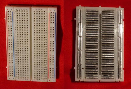
Figure 2-6. (L) Front of a breadboard; (R) back, with backing pulled off
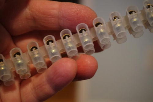
Figure 2-7. A terminal block
Resistors have many uses. The most common things you will use them for in conjunction with an Arduino are as a pull-up or pull-down, as a voltage divider, or for current limiting. A pull-up or pull-down uses a fairly “strong” resistor (one with a high resistance), almost always at least 1 kiloohm (a kiloohm is 1000 ohms, abbreviated kΩ or K) and usually 10–200K so that when there is a voltage across it, very little current will flow. When connected to an input pin, a pull-up resistor connects the pin weakly to VCC until something connects it more strongly to a different voltage by using a lower resistance. A pull-down resistor does the same, but pulls the voltage down to GND instead of up to VCC. This prevents an input pin from floating, keeping it in a known state until it is activated by another device.
What happens if you have a pull-up and a pull-down connected to the same pin? When this happens, current flows between VCC and GND, and the voltage drops across each resistor. The total voltage dropped is equal to VCC, but each resistor drops a different amount of that voltage, which is inversely proportional to its proportion of the total resistance. This is called a voltage divider. In a 5V circuit with an 82K resistor connected to VCC and an 18K resistor connected to GND (for a total resistance of 100K), the point where these resistors connect to each other measures 18% of VCC, or 0.9V. The same would happen if you used an 82Ω resistor and an 18Ω resistor, but 1000 times as much current would run through the resistors, being wasted as heat. Without a pin connected to the center, these two resistors would function in the circuit just like a single resistor with a resistance equal to the sum of the two resistors.
A potentiometer is a special type of resistor with a third conductor in the center that can slide along the resistor to connect to it in different places, usually attached to a knob. With VCC connected to one end, GND to the other, and an analog pin at the center, you can turn the knob and use the analog pin to read the position of the potentiometer’s knob.
LEDs
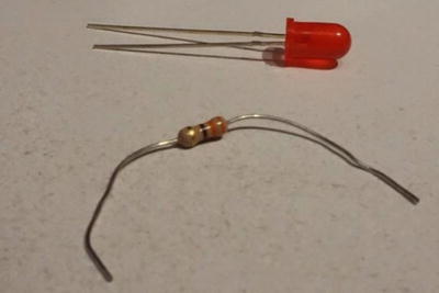
An LED is a component that lights up when a current runs through it. Diodes have the unique property of a forward voltage drop, a specific amount of voltage that they will block, which depends on the type of semiconductor used to make them. Beyond its forward voltage drop, an LED has very little resistance, and it may allow enough current to damage the LED. If the LED is controlled by an output pin, this current can damage the microcontroller, too. Because each resistor in series increases the total resistance, a resistor can be added in series to limit the current flowing through a load. How much resistance is required depends on the voltage that it needs to drop (supply voltage minus the LED’s forward voltage drop) and the desired current. Figure 5-6 shows a typical LED and resistor side by side.
Arduino circuits need to be powered somehow. Often an Arduino is plugged into a USB port on a laptop and gets its power from there. Arduino boards also include voltage regulators that can be used to power them from a battery or a wall wart–style power supply.
![]() Tip Tools like Fritzing (www.fritzing.org) and 123D Circuits (www.circuits.io) allow you to design your circuit as a virtual breadboard or a circuit schematic and then turn them into a design for a custom circuit board. Once you have a circuit board design, you can look for online services that will fabricate your PCB and send it to you, so you can solder your components on.
Tip Tools like Fritzing (www.fritzing.org) and 123D Circuits (www.circuits.io) allow you to design your circuit as a virtual breadboard or a circuit schematic and then turn them into a design for a custom circuit board. Once you have a circuit board design, you can look for online services that will fabricate your PCB and send it to you, so you can solder your components on.
Raspberry Pi
A Raspberry Pi is a small computer that can run moderately sized programs. It is the most well known of a class of devices known as single-board computers. A Raspberry Pi is about the same physical size as some Arduino boards, but it has a lot more processing power. Unlike the 8-bit microcontrollers from the ATmega family on most Arduino boards, which typically run at 16 Mhz, a Raspberry Pi has a 32-bit ARM processor running at least 700 Mhz, making its performance roughly equivalent to a desktop PC from the late 1990s.
ARM chips like the one that runs a Raspberry Pi are also found in smartphones, tablets, smart televisions, and television set-top boxes. Unlike these devices, a Raspberry Pi does have a few general purpose input and output pins, but they are not quite as versatile as those on an Arduino. Unlike an Arduino, the Raspberry Pi is intended to be used with an HDMI monitor and a USB keyboard and mouse like a desktop PC, though there are uses for a Rasberry Pi that require neither.
Single-board computers like the Raspberry Pi usually run the Linux operating system, an open source PC operating system based on Unix. Linux is free, relatively easy to modify, and capable of running on a wide variety of processors. It also has the advantage that graphical desktop interfaces comparable to those of Windows and Mac OS X, are available but optional parts of the operating system. Whereas the modern versions of those operating systems require several gigabytes of both storage and RAM, lightweight distributions of Linux are available that fit into a few megabytes or less. One commonly used Linux version optimized for the Pi is called Raspian, which is available for free from www.raspbian.org.
Why would you use a Raspberry Pi instead of a desktop? In a word, cost. A Pi runs about $35 as of this writing, and can perform many of the functions of a minimalist desktop. If you want a utter bare-bones computer that can run several programs at a time with a real operating system, the Pi is appropriate for you.
![]() Tip There are a lot of books about using Raspberry Pi. Some focus on how to connect it to other components or sensor networks (along with an Arduino), and others focus on the Linux programming aspect of it. This is a rapidly expanding field, and a web search at your favorite online bookseller should reveal a lot of options. More generally, the Raspberry Pi Foundation’s website at www.raspberrypi.org is a good place to get more information.
Tip There are a lot of books about using Raspberry Pi. Some focus on how to connect it to other components or sensor networks (along with an Arduino), and others focus on the Linux programming aspect of it. This is a rapidly expanding field, and a web search at your favorite online bookseller should reveal a lot of options. More generally, the Raspberry Pi Foundation’s website at www.raspberrypi.org is a good place to get more information.
Starting More Simply
If all this seems too intimidating and complex, there are simpler packages designed for beginners that avoid wiring altogether. Some have resistors and other components on stickers (such as Circuit Stickers, circuitstickers.com), which you can then connect by drawing around them with a copper ribbon or conductive-ink pen. Other systems enclose the components in sturdier plastic packages and have magnetic connections, like LittleBits (http://littlebits.cc) and LightUp (www.LightUP.io). LightUp has an app that allows learners to take a picture of their magnetically connected circuits and get feedback on whether they are connected correctly or not. Their circuits can connect to an Arduino, too. Chapter 8 discusses these products further, with other innovative interface and augmented reality products.
Things You Need To Learn
As you have gathered if you have read this chapter, learning to use these devices is not a simple process. However, the flip side of this is that you (and your students, if you are planning on using these technologies to teach) will learn a lot in the process. There are several ways to go about scaling up. Probably the commonest way is to start with very simple projects that require you to learn a bit about each of the aspects as you go. (See the upcoming “Where to Learn Online” section for more on where to learn about these technologies.) However, if you want to build a full-up curriculum, probably the way to go about it would be to teach some circuit basics first, followed by a bit about how computer coding works in C (the language used in Arduino programming) or something similar. If you want to cut to the chase, however, and jump right in to Arduino projects, buying a kit that comes with an instruction book might be the way to go.
![]() Tip It is tempting to find a project that you want to do and to try to work backwards from that to figure out what to learn. This can be a good approach in the long run, but you need to figure out how to break out some simpler pieces to start with to build up your knowledge in an orderly, bite-sized way. This sounds obvious, but we have found most people starting out see a spectacular project and want to start there without any first steps. You may need to play scales a little bit before you try that concerto, but by all means use your big goal as an inspiration and guide!
Tip It is tempting to find a project that you want to do and to try to work backwards from that to figure out what to learn. This can be a good approach in the long run, but you need to figure out how to break out some simpler pieces to start with to build up your knowledge in an orderly, bite-sized way. This sounds obvious, but we have found most people starting out see a spectacular project and want to start there without any first steps. You may need to play scales a little bit before you try that concerto, but by all means use your big goal as an inspiration and guide!
The single best safety device is a competent adult who keeps an eye on beginners of any age. If you are an adult beginner and in charge of teaching children, our suggestion is that, to paraphrase the airline safety video line, you attend to yourself before trying to help others. As general good practices, use appropriate eye protection, have a fire extinguisher that works, and be sure you know how to use it. Avoid loose and/or flammable clothing and ventilate work areas well. Read manufacturer’s suggestions for use of any particular device or process.
One good entry point into this space is to learn about the basics of circuit design. You can do that by playing with an Arduino project, or you can buy one of the circuit-sticker or other simplified alternatives. The intent of the Arduino itself was for it to be a good beginner platform, so there are some limits on how low you can go first.
Learning to Code
Using processors requires that you learn how to write code. As noted at the beginning of this chapter, you can learn Processing and its environment as a step toward Arduinos. Or you can start out teaching yourself C or one of the similar languages in its family such as C++, Java, or Python. Unfortunately, there are no shortcuts in learning to code, but a good way to get started is to do progressively harder projects, starting with having your computer print out “Hello World.”
As you saw in Chapter 1, Joan and Rich both came into this sphere from the software side (Joan pretty much has stayed there, learning enough about the hardware to get by). Depending on the types of projects you want to do, learning to code or at least becoming computer-literate is the first gateway you will need to pass. There are many learn-to-code classes out there, both in person and online; you might check your local community calendar to see if one is being offered at an appropriate level, or ask at a local makerspace. You will need to load some sort of development environment onto your Mac, Windows, or Linux computer to get started.
Learning to Solder
If you want to have projects around for a while, you probably want to advance away from projects on a breadboard (which are pretty fragile) and solder your projects together. You can try to find a “learn to solder” class at a makerspace or community college nearby, or if that is not possible, do what Rich did: learn from online tutorials and a lot of practice.
If you go that route, though, be sure you get a soldering iron that has temperature control (a dial for temperature, not wattage) because otherwise you will have no temperature regulation, which makes it a lot more difficult to keep the iron from damaging components or itself. Solder contains lead, which can be dangerous, and there are various opinions out there about how old you need to be to solder. Obviously, you should not eat and solder at the same time, and you should ventilate the area (there are some soldering fans with a filter made specifically to help manage solder fumes). Eye protection is always a good idea during any project.
Electrical Safety
The electronics in this chapter are designed to run at a low voltage. However, any system should be unplugged and unpowered (even from a computer) when you are working on it. If some part of the system is ultimately plugged into a wall, never assume that everything is at 5V. Be careful to avoid getting the circuits wet.
It also helps to be neat. A rat’s nest of wires is never a good thing, besides being hard to debug. Plan your project ahead and think about your wiring before you start to hook it all up.
Where to Learn Online
Community colleges and makerspaces are probably the best bet for a class in the near term; you might also try your public library, since libraries in many municipalities are exploring adding hackerspaces. If you prefer to learn on your own versus taking a class, online Arduino forums are good places to start , Check out http://forum.Arduino.cc, letsmakerobots.com, instructables.com, and hackaday.com. The vendors noted in the next section have forums, too.
How Much Does Getting Started Cost?
The price of getting started depends somewhat on what you are doing. If you buy a kit from Sparkfun (sparkfun.com), Adafruit (adafruit.com), or the Makershed (makershed.com), you can get started for $50–$100 for one kit. Be sure you buy a kit that includes the processor you want to learn (Arduino or Raspberry Pi, as the case may be). Some starter kits include everything but the processor, assuming that you bought it elsewhere. The software is open source and free—but you might budget for a few books, manuals, and add-on shields as well. If you decide to also learn to solder, you can find beginner kits for that too. You might get an experienced friend or recommendations in a forum when you start to buy this next level of tool. Later chapters discuss projects that use these basic processors, and we give you a general idea of costs for beginner projects in each end-of-chapter section.
Summary
In this chapter, you learned about the Arduino and Raspberry Pi ecosystems and how to get started learning how to use them. We noted that Arduinos are particularly good for taking signals from sensors or controlling motors, LEDs, and other physical objects. A Raspberry Pi, on the other hand, is a small but full-function computer on a credit-card-sized board. Using them requires learning a bit about circuits, computer code, and your application. The chapter concluded with some notes about how to acquire that knowledge. Chapters 3 through 8 will now talk about applying these technologies, or similar ones, in applications ranging from 3D printing to electronics-infused clothing items.