3.3 Photovoltaics and Product Integration
3.3.1 Introduction
It was more than a century since the discovery of the photovoltaic (PV) effect – the conversion of photons to electricity – by Becquerel in 1839 (Becquerel, 1839) before solar cells were developed. In the 1950s, PV solar cells were developed at Bell Telephone Laboratories in the United States with the purpose to apply them in products that lacked permanent electricity supply from the mains (Chapin, Fuller, and Pearson, 1954). The solar cells were called silicon solar energy converters, commonly known as the Bell Solar Battery (Prince, 1955). Furnas (1957) reports,
“The Bell Telephone Laboratories have recently applied their findings in the transistor art to making a photovoltaic cell for power purposes...and exposed to the sun, a potential of a few volts is obtained and the electrical energy so produced can be used directly or stored up in a conventional storage battery....The Bell System is now experimenting with these devices for supplying current for telephone repeaters in a test circuit in Georgia. As to cost, one radio company has produced a power pack using this type of photoelectric cell for one of its small transistorized radios.”
The Journal of the Franklin Institute mentioned as early as 1955 that “these (solar) batteries can be used as power supplies for low-power portable radio and similar equipment” (Anonymous, 1955). Expectations regarding the applicability of photovoltaic cells in products were high; Sillcox (1955) reports on predictions by researchers of New York University “that small household appliances like toasters, heaters or mixers using the sun's energy might be in fairly widespread use within the next five years (i.e., 1960).” These predictions have not become reality, because at that time the costs of silicon PV cells were about $200 per Watt for high-efficiency cells (Prince, 1959) – where 12% was considered high efficiency – and the costs of a dry cell to operate a radio for about 100 hours would be less than a dollar (Furnas, 1957). Therefore, it was believed that the solar battery could be an economical source for all except the most special purposes. As such by the end of the 1950s silicon PV solar cells were applied as a power supply for satellites (Zahl and Ziegler, 1960). The Vanguard TV-4 test satellite that launched on March, 17 1960 was the first satellite ever equipped with a solar-powered system and it announced a new area of space technology with solar-powered satellites.
At present, various applications of photovoltaic solar cells exist ranging from stand-alone PV systems, satellites, grid-connected PV, building integrated PV systems, and a very large system with a power of tens of megawatts. The focus of this chapter, however, is on product-integrated PV (PIPV) from the perspective of industrial design engineering. PIPV can be applied in consumer products, lighting products, boats, vehicles, business-to-business applications, and arts (Reinders and van Sark, 2012).
3.3.2 PV Cells
The efficiency of a PV solar cell is an important variable in the design of product-integrated PV, because it determines the power that can be produced for the application designed. The efficiency depends on the PV material and technology of the cell and the intensity of irradiance that impinges on a PV cell surface. In addition, the temperature of the PV cell and the spectral distribution of the light affect the efficiency.
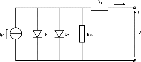
If a solar cell is illuminated, a photocurrent Iph is generated. This photocurrent is in most cases linearly related to the intensity of irradiance. Because of the semiconductor materials in the PV cell, the electric behavior of a PV cell can be represented by a current source in parallel with two diodes, D1 and D2. A series resistance, Rs, and a parallel resistance, Rsh, add to this electric circuit, as shown schematically in Figure 3.3.1.
Figure 3.3.1 Equivalent circuit of a solar cell represented in the two-diode model
The electric behavior or current–voltage characteristic (I–V curve) of a PV cell is described by the following (Green, 1982):
(3.3.1) ![]()
Here Is1 and Is2 are the saturation currents of the two diodes, respectively, and n1 and n2 are the quality factors of the two diodes. In general, n1 will not deviate much from 1, and usually n2 = 2 if no imperfections occur. V is the voltage over the circuit, T is the temperature, and k is the Boltzmann constant. Figure 3.3.2 shows the I–V curve of a solar cell at a certain irradiation. It crosses the y-axis at the open circuit voltage, Voc, and the x-axis at the short circuit current, Isc.
Figure 3.3.2 Above: The current–voltage characteristic of a solar cell. Below: The power–voltage characteristic of a solar cell
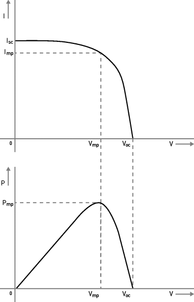
In Figure 3.3.2 it is shown that the I–V curve of a PV cell has one point that delivers maximum power. This point is called the maximum power point, Pmp, and is characterized by Vmp and Imp. This maximum power point is used to determine the efficiency, η:
(3.3.2) ![]()
Here, AG is the optical power falling onto the solar cell, with A the solar cell area and G the irradiance. Please note that from the two-diode model, it follows that if the operational voltage, V, of the cell deviates from the maximum power point settings, the efficiency will drop accordingly.
Single values of efficiencies of solar cells are usually efficiencies at so−called standard test conditions (STC), ηSTC, which means that it is measured at 1000 W/m2 irradiance, AM 1.5 spectrum, and 25°C cell temperature.
PV cells are made from several semiconductor materials using different technologies. These materials yield various efficiencies. The most well-known solar cell technology is the single-crystal silicon wafer–based solar cell, indicated by c-Si. It has improved significantly for nearly 60 years, and it has always been and is still today the dominant solar cell technology. Crystalline silicon solar cell technology also represents multicrystalline silicon solar cells, indicated by m-Si. Both c-Si and m-Si are so-called first-generation solar cells (Green, 2003).
Besides this, second-generation solar cells have been developed with the intention to find a cheaper alternative for crystalline solar cell technology by using less material. They can usually be characterized as thin-film solar cells. Several semiconductor materials allow for the production of thin films, namely, copper indium gallium diselenide (CuInGaSe2, abbreviated to CIGS), cadmium telluride (CdTe), hydrogenated amorphous silicon (a-Si:H), and thin-film polycrystalline silicon (f-Si). Also, thin film PV cells can be made from organic materials. Firstly, dye-sensitized cells (DSCs) consist of titanium oxide nanocrystals covered with light-absorbing organic molecules. Secondly, polymer organic solar cells are made from conducting polymers with, for example, light-absorbing C60 molecules. A third group of solar cells is made from compounds from the elements Ga, As, In, P, and Al, also denoted as III–V technology. The specific cells are named after their compounds, for instance GaAs, GaInP, or InP. These PV cells have been developed for space applications because of their high efficiency. Nevertheless, they are increasingly being applied in terrestrial concentrator systems. Table 3.3.1 shows typical efficiencies for the PV technologies mentioned in this section.
Table 3.3.1 Characteristic efficiencies and spectral response range of several PV technologies adapted from Kan (2006), updated with Kazmerski (2010) and Green et al. (2011)
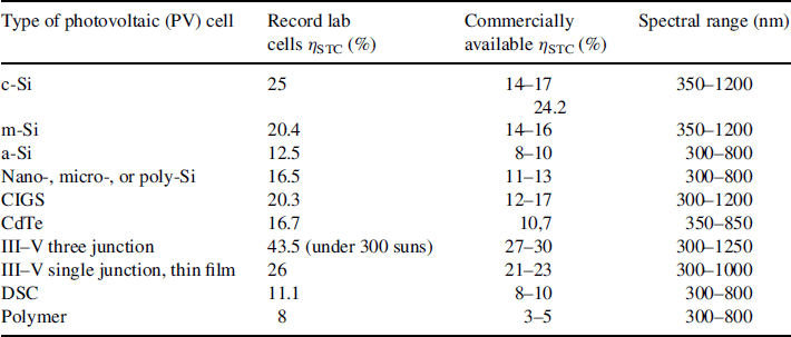
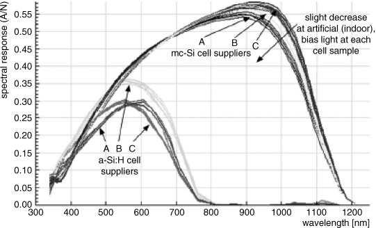
The sensitivity of each solar cell strongly depends on the wavelength of the light falling onto the solar cell. The sensitivity as a function of wavelength is called the spectral response (expressed in [(A/m2)/W/m2)] or in [A/W]), and it is quantified by measuring the short-circuit current occurring at illumination with a monochromatic light beam. Table 3.3.1 shows the range of spectral response of different cell technologies, which is determined by the band gap of the semiconductor material and the charge generation and recombination processes that internally take place in a solar cell. Figure 3.3.3 presents spectral response curves of samples of a-Si and c-Si under an AM1.5 spectrum by Reich et al. (2005).
Figure 3.3.3 Spectral response of a-Si samples and m-Si samples from Reich et al. (2005)
3.3.3 Irradiance and PV Cell Performance
Outdoor Irradiance in Relation to Solar Cell Performance
Irradiance (G) is the power density of light expressed in W/m2. In daytime, outdoor irradiance is predominantly determined by sunlight. In Figure 3.3.4, the spectral distribution of the sunlight falling onto the earth's surface is shown. This spectrum resembles the spectrum of a black body with a temperature of 5700 K and is determined by the path length of the sunlight through the atmosphere (the air mass, or AM): AM 0 is the extraterrestrial spectrum. The various “dips” in the spectra arise because of absorption in the atmosphere, by water vapor among other things. In addition, the spectrum is influenced by scattering taking place in the atmosphere.
Figure 3.3.4 The wavelength-dependent AM 0 and AM 1.5 spectra of sunlight
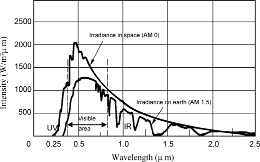
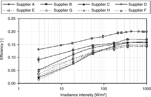
The response of a solar cell depends on the spectral composition of incident light. To be able to compare different solar cells, its efficiency is defined at a standard spectrum. This is the AM 1.5 standard spectrum for terrestrial applications and the AM 0 standard spectrum for space travel applications. Figure 3.3.5 shows for c-Si and m-Si solar cells measured efficiency curves in the maximum power point (Reich et al., 2009). It can be seen that the efficiency steeply drops with respect to the STC efficiency with decreasing irradiance, which can be explained using the two-diode model and appropriate values for its parameters.
Figure 3.3.5 Measured irradiance intensity-dependent efficiencies of various Si solar cells by Reich et al. (2009)
Indoor Irradiance
Indoor irradiance usually consists of a mixture of sunlight that enters a building through windows and skylights, and artificial light originating from different light sources, such as incandescent lamps, fluorescent lamps, and light-emitting diodes (LEDs).
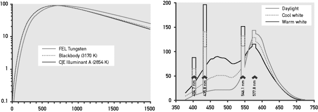
Müller has conducted extensive research on the measurement of indoor irradiance (Müller, 2010; Müller et al., 2009). She reports that though indoor irradiance can exceed 500 W/m2, basic orders of magnitude typically are about 1–10 W/m2 with worst-case scenarios in the winter without the use of artificial light in the range of 0.1 W/m2. For surfaces oriented toward windows, solar radiation will contribute most; for surfaces oriented toward electric light, the latter will contribute most of the radiation. These features can be important concerning the dominating spectral distribution of irradiance that can be converted to electricity by PV solar cells. In other words, the spectral range of irradiance from sunlight is from 300 up to 4000 nm, whereas the spectral distributions of artificial light are narrower. For instance, artificial light emitted by incandescent lamps has a spectral range from 350 up to 2500 nm, by LEDs from 400 to 800 nm, and by fluorescent lamps from 300 to 750 nm (Kan, 2006). In Figure 3.3.6, measured spectra of incandescent light sources and fluorescent lamps are shown.
Figure 3.3.6 Spectra of incandescent lamps and typical fluorescent lamps from Ryer (1997)
Solar Cell Performance at Indoor Irradiance
Several studies have been devoted to solar cell performance under weak light or indoor irradiance conditions. These studies were conducted by Randall (2006), Randall and Jacot (2003), Reich et al. (2005, 2009), Girish (2006), and Gong et al. (2008).
Here we would like to refer to the most recent study in this field by Müller (2010; Müller et al., 2009), who has simulated and measured the performance of different PV materials for different spectral distributions in order to identify maximum efficiencies and the optimum technology. For different PV technologies, efficiency from 4% to 16% is found under conditions of artificial light. Surprisingly polymer solar cells' efficiency is only slightly decreased with respect to their STC efficiency. Crystalline silicon solar cells in general perform better than a-Si solar cells in this experiment.
3.3.4 Rechargeable Batteries
A PIPV product that is powered by solar cells needs an energy storage device. This could be a capacitor that is suitable for very short periods of storage (Kan, Verwaal, and Broekhuizen, 2006) or a battery that can be used for longer periods of energy storage. Here we refer to Section 3.2 of this book, which focuses on batteries, in particular on secondary batteries that can be recharged.
3.3.5 System Design and Energy Balance
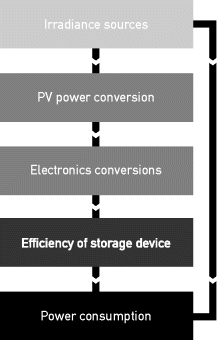
PV system design in a product context is a rather complex task because of the interdisciplinary character of product development. It not only concerns an appropriate energy balance of the system components, but also addresses issues related to manufacturability, costs, safety, operating temperatures, and environmental aspects. Finally, the integration of PV systems in products should result in customer benefits like (1) a better functionality, increased comfort, or autonomy of a product; (2) less dependency from the electricity grid; (3) smaller batteries; and (4) fewer user interaction for recharging batteries (Reinders, 2002). Figure 3.3.7 aims to represents system design during product development of PIPV by showing the relationships between the user, the product, and the integrated PV system and indicators that might be relevant for the decision making in the conceptual design stage. These indicators will be related to energy matching, final weight of the product, area required, volume, customer benefits, costs of the product, and safety and environmental indicators. Apart from this it should be possible to produce a product with existing manufacturing processes. Within this vast context the energy balance of a certain combination of PV system components, product, and user can be estimated, using the flow scheme shown in Figure 3.3.8. Next we will give some guidelines for estimations of the energy balance of a PIPV.
Figure 3.3.7 Issues involved in the integration of renewable energy sources, in particular PV technologies in a product context Adapted from P. Diaz (2010)
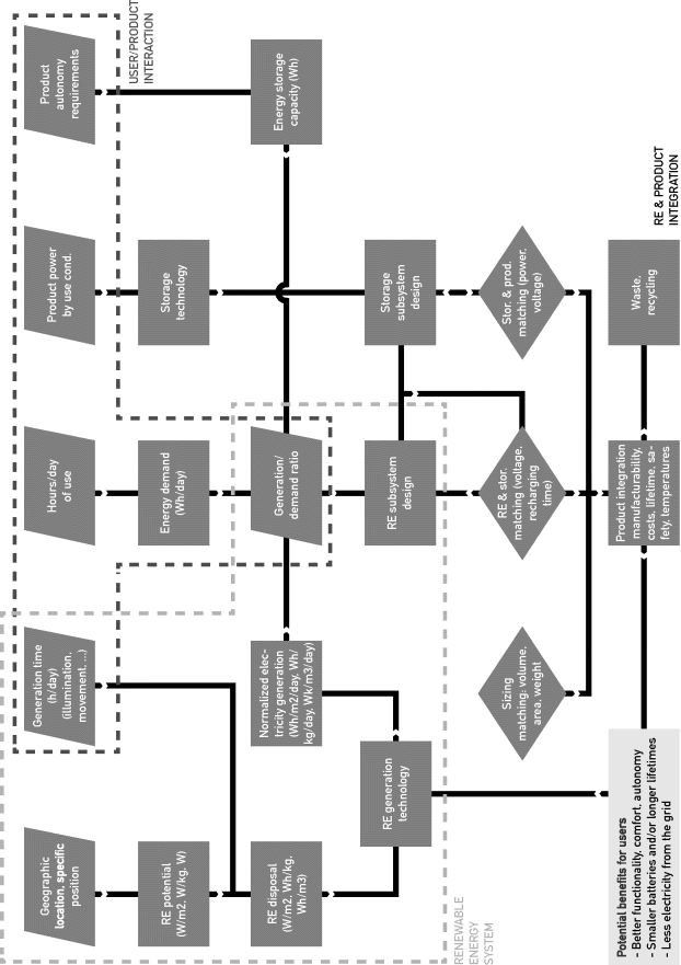
Figure 3.3.8 Flow scheme showing the energy chain of a PIPV
Irradiance
Irradiance can be measured on locations of expected use of a PIPV. However, it might be convenient to simulate irradiance during the design process: Reinders (2007), Reich et al. (2008, 2009), and Tiwari and Reinders (2009) developed different methods to determine irradiance in CAD tools. Moreover, at present the widely used design environment 3D Studio Max comprises a module with the established Perez model for irradiance simulation.
PV Power Conversion
The conversion of irradiance, G, should at least include the irradiance dependency of the efficiency, ηPV, of solar cells. In a certain period of time, the energy EPV that can be produced by the solar cells is given by
(3.3.3) ![]()
Electronic Conversions
Power electronics needed to convert DC into AC power in the device have a certain conversion efficiency that should be taken along in the estimates of the energy balance, in particular in low-power devices.
Efficiency of the Storage Device
The efficiency of a battery in a PIPV is affected by the charging patterns of the PV cells. Therefore, some recommend determining the solar energy to charge conversion efficiency and to optimize it. This efficiency is given by
(3.3.4) ![]()
Where ![]() is the average voltage (in V), Q is the charge increase (Ah), G is irradiance (in W/m2), A is the area of PV cells (m2) and T is the time interval (in s).
is the average voltage (in V), Q is the charge increase (Ah), G is irradiance (in W/m2), A is the area of PV cells (m2) and T is the time interval (in s).
Power Consumption
A reliable estimate of the power consumption of future users of PIPVs can be based on questionnaires and a quantitative insight of the power required for the different functions of a PIPV. The variability between user behaviors can be used to set minimum and maximum values for the area of PV cells needed to fulfill the energy demand of the future users.
3.3.6 Design and Manufacturing of Product-Integrated PV
Opportunities of the integration of PV technology in the final design of a product that can be manufactured partly depend, on one hand, on the visual appearance of PV cells in the context of the product design and, on the other hand, on the possibility to shape and form PV cells and to attach them to the product. Roth and Steinhueser (1997), Reinders and Akkerman (2005), researchers in the EU PV-Accept project (2005), Kan (2006), and Gorter et al. (2010) have addressed these issues.
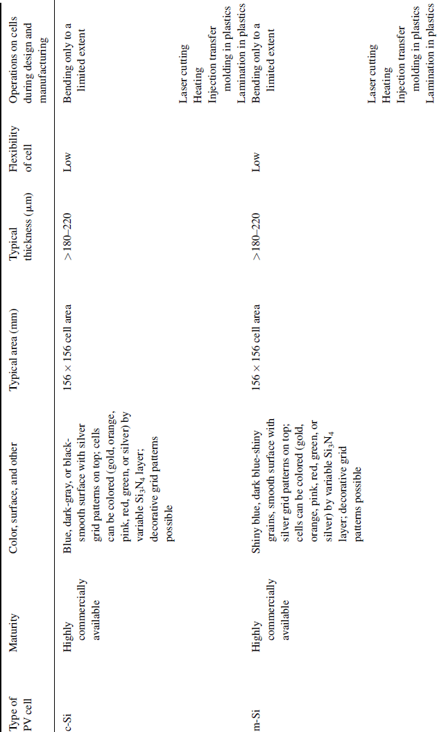
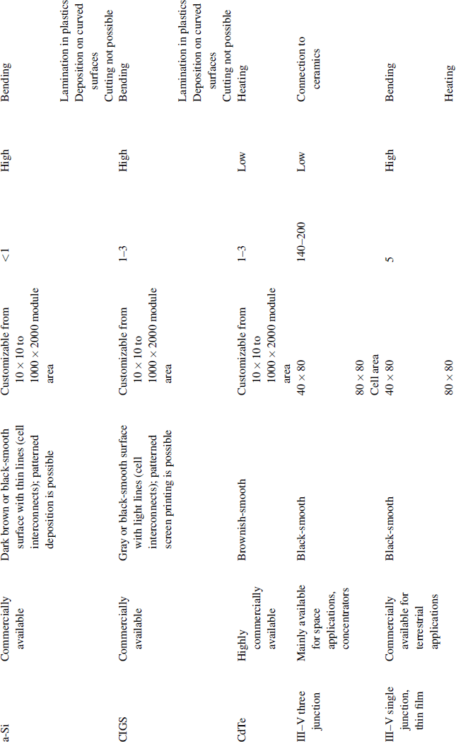
For PV cells, characteristic visual features of different PV technologies and possibilities to shape and form them have been collected in Table 3.3.2. It can be found that visual appeal, flexibility, and the number of possible operations vary considerably among the different technologies. Coloring is possible for c-Si and m-Si technologies, although it will adversely affect the efficiency. For other solar cells the use of colored glass sheets or colored plastics as a cover could bring in more variations with respect to their dark brown and grayish colors. a-Si and CIGS can be produced with customized patterns; c-Si and m-Si can be decorated by grid designs that are different from the common H-pattern. Newly developed back-contact cells may be more appealing from a visual perspective.
Table 3.3.2 Design aspects of different PV technologies, adapted from Kan (2006) and extended with manufacturing data.

PV cells or series of PV cells can be attached on product surfaces in the following ways:
The fourth option has the advantage of preshaping of a series of PV cells in a mold that is injected with the fluid plastic, so-called injection molding.
The selection of glass or plastics – such as epoxies, fluorides, polyolefins, and silicones – that could be applied for the protection of solar cells in products is based on variables like transparency, transmittance, service temperature, thermal expansion coefficient, glass temperature costs, weight, and expected lifetime in relation to the product's expected lifetime. For the last reason, we assume that for PIPV in consumer products, less stringent criteria are set to UV stability and impact resistance compared to PIPV in business-to-business products that must be able to endure harsh outside environments for many years.
3.3.7 Conclusions
PIPV can be applied well in different product categories and for various markets. With the steep decrease of prices of conventional PV technologies such as c-Si, the emergence of low-cost PV technologies such as polymer solar cells, and a slight decrease of the power demand of products induced by technological advances, PIPV might become a respectable widely applied energy source. For instance, PIPV might become common in public-lighting products and other urban furniture in public spaces. Also we expect that the market of PV-powered LED lamps in developing countries might grow in the forthcoming years. In this chapter, it was shown that PIPV can offer energy to products with a wide range of power demand. Therefore we believe that PIPV will be further developed in the field of micro-energy harvesting, that is, for sensors and security, and that it will be applied more often in boats and cars.
