3.4 Fuel Cells
3.4.1 Fuel Cell Principles and Characteristics
Fuel cells are electrochemical devices that convert chemical energy into electricity and heat. Like batteries, fuel cells are so-called galvanic cells: Because of a negative change in Gibbs free energy, the electrochemical reaction is a spontaneous process. The counterpart of the fuel cell is the electrolyzer, which is a forced process.
The core of the fuel cell consists of an electrolyte and two electrodes, the anode and the cathode. Oxidation takes place at the anode, and reduction at the cathode. The electrolyte separates the two electrodes, while at the same time it facilitates the transport of ions to prevent the accumulation of charge at either side of the fuel cell.
In comparison to batteries, fuel cells are open systems: A continuous feed of reactants is needed to sustain the electrochemical process, while the products have to be expelled. The increase of power density is often a combination of optimizing the activity of the electrodes, minimizing ohmic resistances, and maximizing the rate at which reactants can reach the reaction interface. A schematic drawing of a series of three cells in a fuel cell stack is shown in Figure 3.4.1, including the flows of gas, ions, and electrons.
Figure 3.4.1 Schematic drawing of a fuel cell stack containing three repetitive units, using a polymer electrolyte membrane fuel cell (PEMFC) as an example
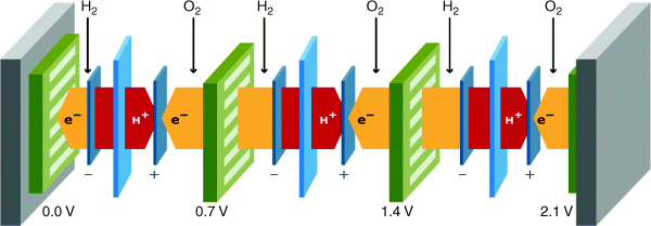
The basic requirements to the separate components become obvious when observing Figure 3.4.1. The electrolyte not only needs to be ion conductive but also needs to separate the reactant gases hydrogen and air, and it needs to be an electronic insulator. At the electrodes, the electrochemical reactions take place. Access for gas, ion, and electrons to the reaction interface is required at both electrodes, which leads to the need for a careful design of the electrode structure at the submicrometer scale. The flow plates connect the individual cells electronically, contain flow patterns to distribute the reactant gas over the cell area, and contain a flow field for cooling to dissipate the heat; the heat generation is typically in the same order as the electric power generation, the electric efficiency being 50–60% in most fuel cells.
3.4.2 Comparison of Fuel Cell Types
Six basic types of fuel cells have emerged, with a number of subtypes that consist of minor variations. The main distinction between these basic types is set by the electrolyte. Both cation- and anion-conducting electrolytes are used, and the temperature at which these electrolytes provide sufficient conductivity is the determining factor for the temperature window of the fuel cell, the materials that can be used for the electrodes, and the fuels that can be fed to the anode. The six fuel cell types and the most important subtypes are given in Table 3.4.1.
Table 3.4.1 Overview of fuel cell types and their most important characteristics (De Bruijn, 2005; Stolten, 2010)
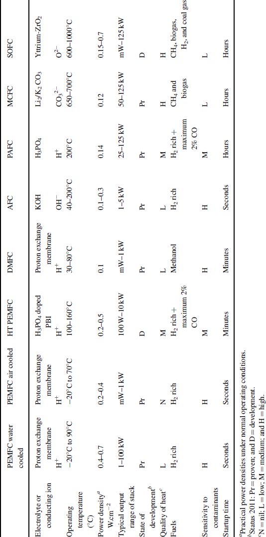
The PEMFC is split into three different varieties: air-cooled, water-cooled, and high-temperature polymer electrolyte membranes (PEMs), as they have distinct characteristics and all are being developed toward separate products. The other fuel cell types have not been diversified to this extent. As one can conclude from Table 3.4.1, there is no single fuel cell type that scores high on all operational properties. A key advantage of high-temperature fuel cells is their tolerance toward impurities. It makes them suitable for operation on a wide variety of fuels, either directly or indirectly using a fuel processor that converts the primary fuel into, for example, synthesis gas (a mixture of hydrogen and carbon monoxide). The same high-temperature operation leads to long start-up times, which makes them unsuitable for a variety of applications such as transport and backup power. While the PEMFC has many advantages over the other fuel cell types, a clear disadvantage is its intolerance toward impurities; it needs hydrogen of high quality. High quality is not necessarily high purity, as inert components such as water, nitrogen, and methane can be tolerated.
3.4.3 Key Characteristics of Fuel Cells
Current–Voltage–Power–Efficiency Relations
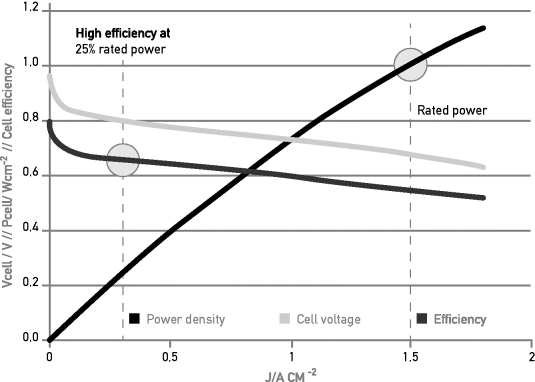
Figure 3.4.2 shows the typical relation between current density, voltage, power, and efficiency of a single fuel cell, in this case for a PEM fuel cell. Similar characteristics can be drawn for the other fuel cell types as well, albeit that the current and power densities vary considerably for the different fuel cell types; see Table 3.4.1. As one can see, there is a clear trade-off between efficiency and power output, which can be translated into a trade-off between fuel efficiency and fuel cell investment cost.
Figure 3.4.2 Cell voltage (green), power density (black), and efficiency (red) versus cell current density. The points of rated power and 25% rated power are indicated. Follow the vertical lines to find the corresponding cell characteristics at these points
The electrical efficiency ηel of the fuel cell stack, referred to the lower heating value of the fuel used, is determined by the voltage at which the individual cells are operated and the utilization (Ufuel) of the fuel:
The maximum theoretical voltage of a fuel cell is reached at zero current, and is referred to as the Nernst voltage. This Nernst voltage depends on temperature, pressure, and the ratio of reactant and product partial pressures. At 25°C and at partial pressures of hydrogen and oxygen of 101 325 Pa, the Nernst voltage amounts to 1.23 V. For a hydrogen–oxygen (air) fuel cell, the relation between the Nernst voltage and partial pressure of hydrogen, oxygen, and water at a given temperature is given by Equation (3.4.2):
in which:
| E° (T) | the standard potential (V) of the fuel cell reaction at temperature T, 1.23 V for a hydrogen–oxygen cell at 298 K |
| R | gas constant, 8.314 J.mol−1 K−1 |
| T | temperature in K |
| F | Faradays constant = 96 484.56 C.mol−1 |
| PO2 | partial pressure of oxygen |
| PH2 | partial pressure of hydrogen |
| PH2O | partial pressure of water |
From equation (3.4.2), it becomes clear that increasing the (partial) pressures of hydrogen and oxygen leads to a higher reversible cell voltage, while a high content of water in the gas phase leads to a lower Nernst voltage. For temperatures different from 298 K, one needs to calculate E° (T), using:
(3.4.3) ![]()
in which
| E° (T) | the standard potential (V) of the fuel cell reaction at temperature T |
| ΔH | enthalpy change of the reaction at temperature T |
| ΔS | entropy change of the reaction at temperature T |
| T | temperature in K |
| F | Faradays constant = 96 484.56 C.mol−1 |
As with many fuel cell reactions, the entropy change is negative, and the Nernst potential generally diminishes with an increase in temperature.
In principle, the fuel cell stack power Pstack is the simple multiplier of cell current Icell, cell voltage Vcell, and the number of cells ncells:
From Figure 3.4.2, it can be concluded that at cell and stack levels, efficiency is highest at zero power, and in general decreases with increasing power.
A fuel cell stack needs to be fed with hydrogen and air to generate power, and generally the power needs to be conditioned to obtain the desired voltage level and quality. For maintaining the stack temperature in the optimal range, a cooling circuit is needed. Figure 3.4.3 gives a simple systems layout for a hydrogen-fed fuel cell system. Hydrogen can be either fed from a hydrogen storage device or generated by a so-called fuel processor. The PEM fuel cell especially needs to remain hydrated; a complex water management system is needed that is not included in Figure 3.4.3.
Figure 3.4.3 Simple systems layout for a PEMFC system

On a systems level, efficiency is lowered by parasitic losses of so-called balance-of-plant components (BOP in equation (3.4.5), such as compressors, humidifiers, and power conditioning:
Net system power refers to the useful power produced by the fuel cell system available for propulsion. This net system power is obtained by subtracting the power use of the balance-of-plant components from the power output of the fuel cell stack.
As the power consumption of these components does not necessarily vary proportionally with the net system power output, system efficiency often follows a trend as illustrated in Figure 3.4.4 for two succeeding generations of automotive fuel cell systems.
Figure 3.4.4 PEMFC vehicle systems efficiency based on composite data generated from fuel cell vehicles taking part in the demonstration fleet in the United States, for two generations (NREL, 2009)
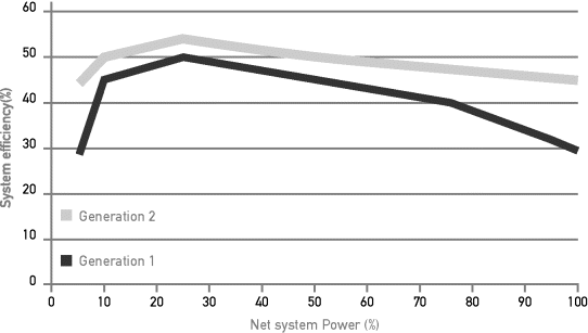
Combustion engines generally show an increase of efficiency with increasing power output, with especially low efficiency at partial load. Whereas fuel cell systems of generation 1, displayed in Figure 3.4.4, had difficulties to beat combustion engines at high loads, today's systems, represented by generation 2 in Figure 3.4.4, have improved such that over the whole output range, fuel cell systems offer superior efficiency (Froeschle and Wind, 2010). This is due to both improved cell performance and balance-of-plant components with low power consumption.
It can be concluded that stack and system efficiency depend on many factors. At constant fuel utilization, the operating voltage determines the electrical stack efficiency. At a given current–voltage relation, which is determined by the fuel cell properties and the stack design, higher power generally leads to lower electrical efficiency at the stack level. The proper design of the system and the selection of balance-of-plant components are decisive for net system efficiency. For the total well-to-wheel efficiency, the complete fuel supply chain should be taken into account. Given all these complications, fuel cell efficiency numbers are not included in Table 3.4.1. Equations (3.4.1) and (3.4.4) give the basic relation between the fuel cell efficiency when operating on hydrogen and oxygen and the cell voltage. A good insight in complete chain efficiencies for vehicles can be obtained from the “Well-to-Wheels” study published by the JRC (2007).
Modular Setup, Enabling Continuous Increase of Power Output
A single fuel cell has a typical power density of 0.1–0.7 W.cm−2, depending on fuel cell type, operating conditions, and cell voltage. The voltage, current, and power requirements set the design of the fuel cell and fuel cell stack. At given cell characteristics, such as those displayed in Figure 3.4.2, the point of operation can be chosen and renders the cell current density and power density. Cell and stack current are then determined by the cell area, while the stack voltage and power are set by the number of individual cells put in series. With a given design, one can vary the power output of a fuel cell stack by a factor of around 5, just by the variation of the number of individual cells put in series. A fuel cell system can contain a number of stacks, put in series, in parallel, or a in combination of these, leading to the desired system voltage and current. With a single fuel cell stack design, a power range between 2 kW and 1 MW can thus be covered. This offers a flexibility that is unsurpassed by competing technologies.
Low or No Emissions
The key benefit of fuel cells is the low level of harmful emissions when compared to many other conversion devices. All fuel cells operate below the temperature where nitrogen and oxygen combine to nitrogen oxides, which lies above 1500°C. When hydrogen is used as a fuel, water is the only byproduct. Due to the intolerance of all fuel cells to sulfur, no emissions of sulfur oxides are formed.
High-temperature fuel cells can be fed with simple hydrocarbons, mostly methane or methane-rich gases, or with synthesis gas, a mixture of hydrogen and carbon monoxide. More complex hydrocarbons often lead to carbon deposition, limiting the fuel cell life to far shorter than the required 40,000–90,000 hours.
Fuel cells are thus especially considered where air quality is compromised by the combustion of fuels, such as in cities and buildings. In these cases, fuel cells compete with the only other zero-emission technology, which is the battery. The absence of noise production is a prime benefit of fuel cells and batteries as well.
Split between Energy Storage and Power
The key difference between fuel cells and batteries is the split between power and energy. The fuel cell, being an open system, contains no energy itself. The energy is contained in the fuel, which is stored separately. As an oxidant, both air and oxygen can be used. Oxygen is used primarily in space and submarine applications. In most terrestrial applications, the benefit of higher power densities does not compensate the higher costs and space requirements of oxygen storage.
Whether expressed in driving distance or operating hours, fuel cell systems beat batteries in volume, weight, and cost to a point, because the storage of fuel per unit of energy is lighter, more compact, and cheaper than in batteries (Wagner et al., 2010). Below that point, batteries are more compact and lighter because of system simplicity.
3.4.4 Cost
The cost of fuel cell systems and stacks heavily depends on the power rating of the system and the production volume. As of today, only two fuel cell types are sold on a commercial base: the PEMFC and the DMFC.
The cost of PEM fuel cell systems has come down impressively since the turn of the twenty-first century. An economic analysis that is relevant for today's applications in telecommunications has recently been published by the US Department of Energy in their 2010 Annual Progress Report (Mahadevan et al., 2010). Figure 3.4.5 shows the estimated cost breakdown of a 5 kW PEMFC system, both for the system as a whole and as an estimated cost breakdown of the balance-of-plant components. The cost of a 5 kW system at an annual sales volume of 2,000 pieces was estimated to amount to $7,000 in 2010, and could be reduced with increasing annual production volume of 100,000 units to $4,200 in 2015.
Figure 3.4.5 Estimated cost breakdown of a 5 kW PEMFC system for backup power. Left: Cost breakdown on system level. Right: Cost breakdown of balance of plant components Analysis made for the US Department of Energy (2010)
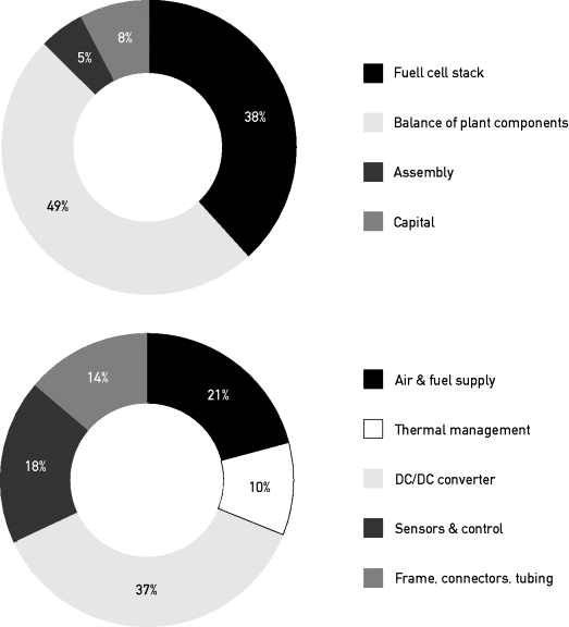
Although the actual cost is at present higher than estimated in this report, the analysis provides a valuable insight into the major cost components of a fuel cell system of 5 kW output with limited production volume. For example, the high cost of the DC/DC conversion is an issue that is overlooked by many integrators.
3.4.5 Fuel Cell Applications and Basic Requirements
Potential Applications and Their Requirements
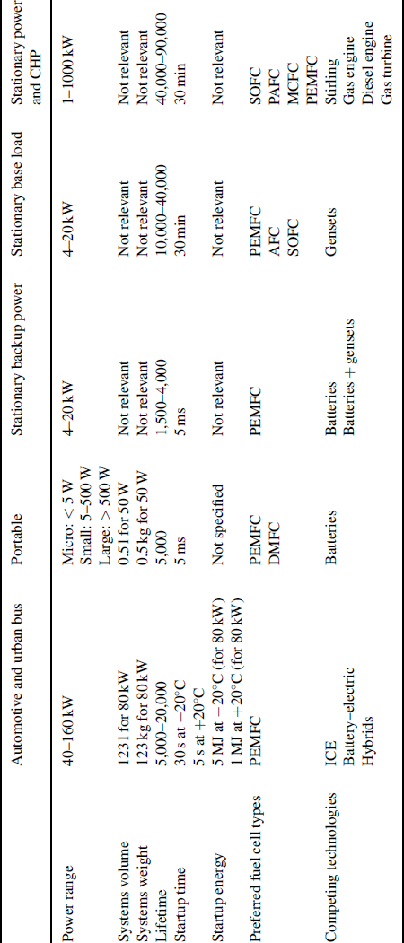
Although most fuel cell types have been considered for a wide range of applications, one can clearly come to a selection of preferred solutions for single applications, taking into account the fuel availability, power density, window of operation, durability, and costs. In the rest of this section, an overview of the main applications is given in conjunction with the current status of various technologies being developed or already applied. Table 3.4.2 gives an overview of the basic requirements for various applications where fuel cells are considered.
Table 3.4.2 Basic requirements for various applications where fuel cells are considered.
3.4.6 Passenger Vehicles
Requirements:
Power range: 40–100 kW; lifetime: 5,000 hrs; system cost: 30–50 €/kW; fuel: hydrogen; shock and vibration resistant; cold start; freeze proof; high power density; and high cycle ability
The application of fuel cells in passenger cars has undoubtedly drawn the most public attention. Already since the early 1970s, prototype fuel cell passenger cars have been showcased. Only since the threat of zero-emission regulation for road vehicles to be introduced in California by 2004, car OEMs have been actively developing passenger cars running on fuel cells that are able to meet consumer expectations, that is, offering functional space, power, and driving range comparable to those of internal combustion engine–powered cars. PEM fuel cells are the only fuel cell type being considered nowadays. State-of-the-art fuel cell vehicles, such as those demonstrated by Honda, Toyota, General Motors, and Daimler, contain fuel cell stacks with a power density of around 2 kW.l−1 that can be used over the expected range of ambient conditions, have a proven lifetime of over 100,000 km, and have a driving range of 500–800 km without refueling (De Bruijn, 2009). The fuel of choice has emerged to be hydrogen; cars using onboard reforming of gasoline or methanol could not meet efficiency, start-up time, start-up energy use, and power density requirements.
Although the latest generation of passenger vehicles is regarded to be fit for the first market introduction, further developments are devoted to the reduction of vehicle cost over its useful life, being a combination of initial procurement costs and durability. Both the costs of platinum per kW output as well as the costs of balance of system components receive the most attention. The latter is thought to diminish considerably when heat and water management can be simplified, for which new fuel cell components are needed that can operate at low humidity level and higher temperature (De Bruijn, 2009).
3.4.7 City Buses
Requirements:
Power range: 75–150 kW; lifetime: 20,000 h; system cost: 1,000 €/kW; fuel: hydrogen; shock and vibration resistant; cold and rapid start; freeze proof; and high cycle ability
In comparison to passenger cars, fuel cells for city buses have longer lifetime requirements, but at the same time are not pushed to the same high power output as fuel cells for automotive are. As in automotive use, only PEM fuel cells are being considered. In practice, similar technology is used, for example the 150 kW Ballard FC velocity–HD6 stack module contains two 75 kW PEMFC stacks that are also used to power passenger cars. The development status is similar to that of automotive use: Fuel cell buses are demonstrated in large numbers across the world and offer functionality comparable to that of internal combustion engine buses, and fuel cell lifetime is over 12,000 hours (Froeschle and Wind, 2010). With respect to development goals, these are similar to those for automotive use, although total cost of ownership is more important than for automotive use, where first ownership costs dominate.
3.4.8 Materials Handling
Requirements:
Power range: 4–20 kW; lifetime: > 10,000 h; system cost: 600 €/kW; fuel: hydrogen; shock and vibration resistant; and high cycle ability
Fuel cell systems for materials-handling vehicles are primarily introduced as replacement for battery-powered vehicles used indoors, where emissions are generally not allowed. PEM fuel cells are primarily used, although direct methanol is being considered as well. Fast refueling, compared to battery charging over hours or labor-intensive swapping of batteries, makes the application of fuel cells economically viable in the short term (US Department of Energy, 2011). As with batteries, weight is not an issue; in fact, forklifts often need a counterweight for safe operation. Size matters, as fuel cell systems are often required to be a drop-in replacement of existing battery packages. Hundreds of fuel cell–powered forklifts have been put into service and meet most important end user requirements, such as lifetime, durability, and power density. Tax credits or subsidies are often still needed to convince industries, partly because fuel costs are higher in the case of fuel cells. Because of many similarities with fuel cell systems for automotive applications, materials-handling vehicles are regarded as their forerunner.
3.4.9 Portable Applications
Requirements:
Power range: micro: < 5 W; small: 5–500 W; large > 500 W; lifetime: 2,000–5,000 h; system cost: 500–2,000 €/kW; fuel: hydrogen, methanol; cold and rapid start; and high cycle ability
Portable fuel cells are in many applications in direct competition with batteries. Energy density is the most important property on which fuel cell systems can offer an advantage, so it is no surprise that the direct methanol fuel cells are most often developed for low-power applications (Garche, 2010). The most successful commercialization of portable fuel cells, by SFC energy, is based on direct methanol fuel cells, having sold over 20,000 fuel cells by 2011 for leisure and defense applications in the 25–90 W range. A lifetime of over 5,000 hours is claimed for a 55 W battery charger system for defense applications.
PEM fuel cells running on hydrogen have a market share as well, and for very small applications even solid-oxide fuel cells have been showcased. The application in the Watt range, for example, for consumer electronics seems to have become commercially out of reach with the successful development of new generations of lithium-based batteries.
3.4.10 Stationary Fuel Cells: Backup Power
Requirements:
Power range: 4–20 kW; lifetime: 1500–4000 h; system cost: 1,000–2,000 €/kW; fuel: hydrogen; cold and rapid start; and high cycle ability
Together with materials handling and portable power, backup power is a market already in full development. The need for high reliability in the telecom sector leads to the installation of backup power systems in both landline and wireless telecom networks. Operating hours can vary highly per location, depending on the reliability of the local grid (Colbow, 2010). Operating hours are spread over 5–10 years with frequent startup and shutdown cycles, and can resemble automotive use, where fuel cell stacks are operated at high current density (1 A.cm−2 and higher) during relatively short times, and are in cold stand still for the largest share of their life. Although voltage cycling leads to higher voltage decay rates when compared to continuous operation, PEMFC systems can meet the application requirements successfully.
3.4.11 Stationary Fuel Cells: Base Load Power
Requirements:
Power range: 5–1000 kW; lifetime: 20,000–90,000 h; system cost: 1,000–2,000 €/kW; fuels: hydrogen, methanol, ammonia, and natural gas; an high efficiency
Base load power generation using fuel cells in the power range of 5–20 kW refers to locations where a power grid is absent, for example, for powering telecom stations in remote locations. On the high end of the range, at 200–1000 kW, power is generated at industrial sites where hydrogen is generated as a byproduct. In both cases, fuel cell stacks are mostly operated at moderate current densities (0.2–0.6 A.cm−2), and consequently high cell voltages (0.7 V and higher), to obtain high fuel efficiency. Using practical hydrogen gas qualities, voltage decay rates as low as 2 μV.hr−1 are realistic for continuous operation using PEMFC. In these applications, PEM, alkaline, and phosphoric acid fuel cells are applied, the first dominating the market.
Alkaline fuel cells have been used especially onboard space missions, operating on hydrogen and oxygen, and supplying both electricity and drinking water for astronauts. The power output of these systems is typically around 6 kW. Being intolerant to carbon dioxide, terrestrial application requires the application of CO2 absorbents, such as limestone (De Bruijn, 2005). Most efforts by companies to launch alkaline fuel cells for stationary applications, especially those advocating the ability of using nonnoble metals for the conversion of hydrogen and oxygen, have failed so far.
3.4.12 Stationary Fuel Cells for Combined Heat and Power Generation
Requirements:
Power range: 1–2000 kW; lifetime: 40,000–90,000 h; system cost: 1,000–2,000 €/kW; fuel: natural gas, biogas, coal gas, kerosene, and propane; and high efficiency
Combined heat and power generation from a very small scale for residential use to a large scale for commercial and industrial uses is a challenging application that has been pursued for the last three decades. While in the 1970–2000 period molten carbonate fuel cells (MCFCs) and phosphoric acid fuel cells were primarily used in the 100–200 kW range (Moreno, McPhail, and Bove, 2008), in the 2000–2010 period the focus was shifted to small systems for residential use. Energy saving is the main driver for combined heat and power, preventing the waste of heat that is typical for central power production at the GW scale. Because operating on the fuel readily available at the location of use is preferred, systems need to operate on natural gas, propane, and even kerosene. The ability to internally reform carbon-containing fuels and the generation of high-temperature heat gives high-temperature fuel cells a clear advantage. Especially solid-oxide fuel cells (SOFCs) have emerged in the 1–50 kW range as the fuel cell of choice (Föger, 2010). For very large systems, where SOFCs seem to lose on cost and manufacturability of large modules, MCFC systems are being applied. Use of biomass-derived gas is in development to reduce overall emissions of greenhouse gases even further.
Because temperature and redox cycles are severe stress factors, SOFCs are not considered for the aforementioned backup applications. For the same reason, previously considered applications as auxiliary power units for transportation, running on pre-reformed liquid fuels such as diesel and gasoline, seem to have become out of reach.
3.4.13 Conclusions
Fuel cells are in development for a wide range of applications, from small sub-Watt portable applications converting methanol directly to power to large systems converting hydrogen- and methane-rich fuels up to the MW scale. Their key advantage lies in their capability to efficiently deliver amounts of power and energy comparable to those of combustion engines, but without the emissions of carbon dioxide, non–greenhouse gas emissions and noise during use. The aforementioned emission over the full energy chain depends on the energy source and the efficiency of the process to convert the primary fuel to the fuel fed to the fuel cell. Depending on fuel and applications, different fuel cell types might qualify as the best choice. Even without legislation on air quality and greenhouse gas emissions, fuel cell systems are entering markets on a commercial basis, by offering a cost and durability that meet customer requirements.
